EP0916552A1 - Ausfahrbarer Überrollbügel für Kraftfahrzeuge - Google Patents
Ausfahrbarer Überrollbügel für Kraftfahrzeuge Download PDFInfo
- Publication number
- EP0916552A1 EP0916552A1 EP98121339A EP98121339A EP0916552A1 EP 0916552 A1 EP0916552 A1 EP 0916552A1 EP 98121339 A EP98121339 A EP 98121339A EP 98121339 A EP98121339 A EP 98121339A EP 0916552 A1 EP0916552 A1 EP 0916552A1
- Authority
- EP
- European Patent Office
- Prior art keywords
- locking
- lever
- stage
- roll bar
- release
- Prior art date
- Legal status (The legal status is an assumption and is not a legal conclusion. Google has not performed a legal analysis and makes no representation as to the accuracy of the status listed.)
- Granted
Links
- 230000006835 compression Effects 0.000 claims abstract description 18
- 238000007906 compression Methods 0.000 claims abstract description 18
- 239000002184 metal Substances 0.000 claims abstract description 7
- 235000005282 vitamin D3 Nutrition 0.000 claims 1
- 239000011647 vitamin D3 Substances 0.000 claims 1
- 239000003380 propellant Substances 0.000 description 4
- 230000001960 triggered effect Effects 0.000 description 3
- 238000010276 construction Methods 0.000 description 2
- 230000036316 preload Effects 0.000 description 2
- 230000005611 electricity Effects 0.000 description 1
- 230000003287 optical effect Effects 0.000 description 1
- 238000005381 potential energy Methods 0.000 description 1
- 238000005096 rolling process Methods 0.000 description 1
Images
Classifications
-
- B—PERFORMING OPERATIONS; TRANSPORTING
- B60—VEHICLES IN GENERAL
- B60R—VEHICLES, VEHICLE FITTINGS, OR VEHICLE PARTS, NOT OTHERWISE PROVIDED FOR
- B60R21/00—Arrangements or fittings on vehicles for protecting or preventing injuries to occupants or pedestrians in case of accidents or other traffic risks
- B60R21/02—Occupant safety arrangements or fittings, e.g. crash pads
- B60R21/13—Roll-over protection
- B60R2021/132—Roll bars for convertible vehicles
- B60R2021/134—Roll bars for convertible vehicles movable from a retracted to a protection position
- B60R2021/135—Roll bars for convertible vehicles movable from a retracted to a protection position automatically during an accident
Definitions
- the invention relates to an extendable roll bar for motor vehicles, consisting of a roll bar and a sheet metal cassette with a Guide body for the roll bar and one with it in driving Active compression spring to extend the rollover in Crash case and with a trigger system consisting of one Locking arrangement with the rollover body with pre-tensioned compression spring and an actuator for releasing the lock in the event of a crash.
- retractable roll bars are found in convertible vehicles Use in which one starts for optical reasons, i.e. firmly built-in riot bar, is dispensed with.
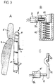
- Fig. 3 shows in part A the known arrangement of the roll bar in Vehicle.
- the roll bar 1 is with a sheet metal cassette 2 Forms outer housing, for example on the rear wall 3 of the vehicle, of a convertible. It is located directly behind the backrest 4 with a headrest 5 of the vehicle seats.
- the sheet metal cassette 2 closes Above approximately flush with the backrest 4.
- a Temple cover 6 made of hard plastic crossbar Roll bar, over which the vehicle rolls in the event of a rollover.
- This The crossbar together with tubular bars, forms the rollover body fastened with its spars in a in the upper part of the sheet metal cassette 2 Guide block connected to the bottom of the cassette Stand pipes is guided in and out.
- the rollover body In the event of a rollover, the rollover body is triggered by a corresponding one Sensor, trigger and drive extended upwards. In the extended Position is the crossbar clearly above the headrest and thus protects the heads of the buckled vehicle occupants at one Rollover.
- a triggering of the extension movement projects through the rear wall 3 Force element 7, which is thus easily after a crash can be replaced.
- Roll bars of the aforementioned type are in varied embodiments with regard to the design of the cassette and the Rollover and the triggering in the event of rollover and the rollover extending drive system become known.
- part B shows a well-known in a greatly enlarged representation direct-acting release system with a cartridge that triggers a pin 8 9 with a pyrotechnic primer 9a in conjunction with a preloaded compression spring 10 for driving the rollover body the element 11 is locked directly with the pin 8.
- the pyrotechnic primer 9a is ignited, it arises a rapid gas expansion within the cartridge 9, the force of which pin 8 pushes to the left, which unlocks the roll bar is and this is extended in a pulsed manner by means of the compression spring 10.
- 3 part C also shows a greatly enlarged illustration indirect triggering with a so-called pin-ejecting pyrotechnic Cartridge 9 'with a primer 9'a, which triggers the pin 8 against one Locking lever 12 presses, which normally with one with the Roll bar connected bolt-like member 13 is latched and in Crash case is released.
- the simplified representation is in the Part B does not drive the roll bar by means of a compression spring 10 shown.
- the pyrotechnic cartridge by a so-called crash magnet be replaced, i.e. an electromagnet, which in the event of a crash Electricity from the vehicle electrical system is applied and the locking and Trigger pin 8 actuated.
- a crash magnet i.e. an electromagnet, which in the event of a crash Electricity from the vehicle electrical system is applied and the locking and Trigger pin 8 actuated.
- the invention is based, based on the task designated retractable roll bar this in terms of Trigger system to design so that in the event of a crash Unlocking the compression spring of the spring drive for the roll bar forces to be applied are smaller than in the known constructions.
- a two-stage locking arrangement is provided, with two in Interacting stages, of which the first stage as Tripping stage in operative connection with the actuating element and the second Level as a locking level with the rollover is in active engagement, and which are designed so that the active connection between the Roll bar and the locking level acting clamping friction on the Active connection of both stages is reduced.
- the two-stage locking arrangement can be done in different ways be solved constructively.
- An advantageously simple construction results if the two-stage locking arrangement from a double lever system exists, with a locking lever on a body by one Axis rotatably attached, at one end a latch extension for one Has active engagement with a locking element on the rollover body, as well which is biased in the opening sense, and with a release lever which is also attached to the base body so as to be rotatable about an axis one end a latch extension for an active intervention with the free end of the Has locking lever, as well as the actuator for releasing the Active engagement of the release lever with the locking lever is assigned.
- a first embodiment is that the preload of the locking lever due to a lateral center offset its axis of rotation relative to the locking element on the rollover body is applicable. In this embodiment, no additional parts needed.
- a second embodiment is that a preloaded torsion spring is provided which is attached to the base body and is in active engagement with the locking lever in the unlatching sense.
- the actuating element of the release system can also be used in different ways will be realized.
- Actuator one ignited by one in a cartridge pyrotechnic propellant charge or a pin actuated by an electromagnet have on the release lever in the event of a crash in the unlocked sense acts.
- the electromagnet can then be switched on without a pin on the release lever act unlocked senses.
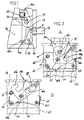
- FIG. 1 shows a schematic representation of a triggering system for an extendable roll bar, consisting of a pin-operated Double lever locking system.
- This double lever locking system has a locking lever 14 which by means of a hook-shaped Pawl extension 14a with a bolt 15 on the rollover body accordingly the representation in Fig. 3 C is latched.
- Practices on the pawl extension 14 a hence the pin 15 by the prestressed compression spring of the drive exerted force.
- This locking lever 14 is rotatable about the axis 17 via a tab-like holder 18 on a base body 16 in a Analogue overturb body and its spring drive receiving sheet metal cassette Fig. 3 A attached.
- the center of the axis 17 is by the distance "a" offset laterally from the center of the bolt 15. This is through the Spring force of the compression spring drive on the locking lever 14 in unleashing senses.
- the double lever system also has a release lever 19 which is around the Axis 20 is rotatably attached to the base body 16. and the one hook-shaped pawl extension 19a with the locking lever 14 at its free end 14b is latched.
- the triggering system also has a symbolically represented one Actuator 9 with a trigger pin 8, which is in operative connection with the free end of the trigger lever 19 is.
- the trigger pin 8 can by means of a Cartridge with a propellant charge analogous to FIG. 3 C or by means of a electromagnetic crash magnets are actuated in the event of a crash.
- the pin 8 If the pin 8 is triggered by a sensor that detects the crash, then it snaps out of the actuating element 9 and presses the release lever 19 left into the position shown in dashed lines. This gives his pawl extension 19a releases the locking lever 14, which in turn is actuated by the pin 15 effective force of the prestressed compression spring of the spring drive for the Transfer roll bar is pivoted such that its pawl extension 14a Bolt 15 on the roll bar releases, whereby the roll bar means its compression spring drive is extended from the cassette.
- the release system is designed so that the release time is not enlarged and that it does not automatically move into the Starting position jumps back, i.e. the reversal is done by a external force on the locking lever 14 against the force of the compression spring the spring drive of the roll bar.
- State A is the idle state
- state B is the triggered state.
- Fig. 2 A is the pawl extension 14'a of the locking lever 14 'with the Bolt 15 latched to the holding end 15a of the roll bar.
- a preloaded auxiliary torsion spring 24 is provided, which has one end is attached to the base body 16 ', and with its free end 24 a to one Opening 14'c bears in the locking lever, such that it the Turn locking lever 14 'about its axis 17' in the unlatching sense want.
- the release lever rotatably mounted on the base body 16 'about the axis 20' 19 ' is bow-shaped and stands with its flat flanged Pawl extension 19'a with a pawl stop 14'b of the locking lever 14 'in a locking operative connection.
- This active connection is through a Torsion spring 21 which is attached at one end to the base body 16 'and the latter free end 21a on the free, magnetized section 19'b having the end of the release lever 19 'and this down presses, made.
- the crash magnet which magnetizes the magnet when it is switched on Section at the end 19'b of the release lever 19 'and thus as shown in Fig. 2 B, the latching with the locking lever 14 ' releases.
- This will remove the linkage with the Bolt 15 on the transfer roller by means of the compression spring of the Roll bar drive exerted moment, supported by the biased auxiliary torsion spring 24 about the axis 17 'in that shown in Fig. 2B Position rotated against a stop 23.
- FIG. 2 The embodiment shown in FIG. 2 is also supported by the potential energy of the preloaded torsion spring 24 and the lever ratios, the clamping friction force on the catch 14'b and 19'a of the release lever 19 ' with the locking lever 14 'smaller than at the latch of the Locking lever 14 'with the bolt 15.
- a trigger pin can be provided which on the underside of the trigger lever 19 ' acts and drives it up in the event of a crash.
Landscapes
- Engineering & Computer Science (AREA)
- Mechanical Engineering (AREA)
- Automotive Seat Belt Assembly (AREA)
- Air Bags (AREA)
- Holders For Apparel And Elements Relating To Apparel (AREA)
Applications Claiming Priority (2)
| Application Number | Priority Date | Filing Date | Title |
|---|---|---|---|
| DE19750693 | 1997-11-15 | ||
| DE19750693A DE19750693C2 (de) | 1997-11-15 | 1997-11-15 | Ausfahrbarer Überrollbügel für Kraftfahrzeuge |
Publications (2)
| Publication Number | Publication Date |
|---|---|
| EP0916552A1 true EP0916552A1 (de) | 1999-05-19 |
| EP0916552B1 EP0916552B1 (de) | 2002-09-04 |
Family
ID=7848857
Family Applications (1)
| Application Number | Title | Priority Date | Filing Date |
|---|---|---|---|
| EP98121339A Expired - Lifetime EP0916552B1 (de) | 1997-11-15 | 1998-11-10 | Ausfahrbarer Überrollbügel für Kraftfahrzeuge |
Country Status (3)
| Country | Link |
|---|---|
| EP (1) | EP0916552B1 (un) |
| DE (2) | DE19750693C2 (un) |
| ES (1) | ES2181110T3 (un) |
Cited By (6)
| Publication number | Priority date | Publication date | Assignee | Title |
|---|---|---|---|---|
| EP1092598A3 (de) * | 1999-10-16 | 2003-08-06 | ISE Innomotive Systems Europe GmbH | Haltevorrichtung für den Überrollkörper eines Überrollschutzsystems |
| EP1186483A3 (de) * | 2000-09-12 | 2004-09-22 | ISE Innomotive Systems Europe GmbH | Fahrzeugfestes Überrollschutzsystem-Gehäuse mit aus- und einfahrbargeführtem Überrollkörper |
| EP1488965A1 (de) * | 2003-06-16 | 2004-12-22 | THOMAS MAGNETE GmbH | Vorrichtung zur Auslösung eines schnell beweglichen Bauteiles |
| EP1541425A1 (de) * | 2003-12-12 | 2005-06-15 | Brose Schliesssysteme GmbH & Co. KG | Haltevorrichtung für eine Fahrzeugsicherheitsvorrichtung |
| WO2006137745A1 (en) * | 2005-06-21 | 2006-12-28 | Kongsberg Devotek As | Releasable holding mechanism and method of use |
| CN101253070B (zh) * | 2005-06-21 | 2011-09-07 | 孔斯贝格德沃泰克股份公司 | 可释放的保持机构及其使用方法 |
Families Citing this family (8)
| Publication number | Priority date | Publication date | Assignee | Title |
|---|---|---|---|---|
| DE19937150B4 (de) * | 1999-08-06 | 2005-03-31 | Daimlerchrysler Ag | Überrollschutz-Vorrichtung für ein Kraftfahrzeug |
| DE10038431A1 (de) * | 2000-08-07 | 2002-02-21 | Volkswagen Ag | Kraftverschluß für eine Fahrzeugsicherheitseinrichtung |
| DE10229635C1 (de) | 2002-07-02 | 2003-07-10 | Ise Gmbh | Überrollschutzsystem für Kraftfahrzeuge |
| DE102004015808B3 (de) * | 2004-03-31 | 2005-03-10 | Ise Gmbh | Überrollschutzsystem für Kraftfahrzeuge mit einem ausfahrbaren Überrollkörper |
| DE102005028928B4 (de) * | 2005-06-22 | 2007-04-12 | Wilhelm Karmann Gmbh | Lösbare Halteeinrichtung zum Halten eines Überrollkörpers einer Überrollschutzvorrichtung eines Kraftfahrzeuges |
| DE102005028960B4 (de) * | 2005-06-22 | 2007-10-25 | Wilhelm Karmann Gmbh | Lösbare Halteeinrichtung zum Halten eines Überrollkörpers einer Überrollschutzvorrichtung eines Kraftfahrzeuges |
| DE102005028923B4 (de) * | 2005-06-22 | 2007-11-08 | Wilhelm Karmann Gmbh | Überrollschutzsystem für ein Kraftfahrzeug, insbesondere für ein Cabriolet |
| EP2246222B1 (de) * | 2010-01-08 | 2012-09-19 | ISE Automotive GmbH | Überrollschutzsytem für Kraftfahrzeuge |
Citations (4)
| Publication number | Priority date | Publication date | Assignee | Title |
|---|---|---|---|---|
| DE3905470A1 (de) * | 1989-02-22 | 1990-12-06 | Autoliv Kolb Gmbh & Co | Ausfahrbarer ueberrollbuegel fuer cabriolets |
| WO1995003952A1 (de) * | 1993-08-03 | 1995-02-09 | Itt Automotive Europe Gmbh | Überrollbügeleinrichtung mit innenführung und aussenführung |
| EP0729867A1 (de) * | 1993-05-03 | 1996-09-04 | Bayerische Motoren Werke Aktiengesellschaft, Patentabteilung AJ-3 | Überrollschutz-Vorrichtung für ein Kraftfahrzeug |
| EP0760314A1 (de) * | 1995-08-28 | 1997-03-05 | Bayerische Motoren Werke Aktiengesellschaft, Patentabteilung AJ-3 | Kupplung für ein in eine Wirkstellung verlagerbares Sicherheitsteil eines Fahrzeugs, insbesondere für einen Überrollbügel |
Family Cites Families (3)
| Publication number | Priority date | Publication date | Assignee | Title |
|---|---|---|---|---|
| DE3930171C2 (de) * | 1989-09-09 | 1996-02-01 | Keiper Recaro Gmbh Co | Überrollschutz |
| DE4342401B4 (de) * | 1993-12-13 | 2004-09-30 | Ise Innomotive Systems Europe Gmbh | Überrollbügel für Kraftfahrzeuge |
| DE19523790C2 (de) * | 1995-07-04 | 2000-07-20 | Ise Gmbh | Ausfahrbarer Überrollbügel |
-
1997
- 1997-11-15 DE DE19750693A patent/DE19750693C2/de not_active Expired - Fee Related
-
1998
- 1998-11-10 EP EP98121339A patent/EP0916552B1/de not_active Expired - Lifetime
- 1998-11-10 ES ES98121339T patent/ES2181110T3/es not_active Expired - Lifetime
- 1998-11-10 DE DE59805392T patent/DE59805392D1/de not_active Expired - Lifetime
Patent Citations (4)
| Publication number | Priority date | Publication date | Assignee | Title |
|---|---|---|---|---|
| DE3905470A1 (de) * | 1989-02-22 | 1990-12-06 | Autoliv Kolb Gmbh & Co | Ausfahrbarer ueberrollbuegel fuer cabriolets |
| EP0729867A1 (de) * | 1993-05-03 | 1996-09-04 | Bayerische Motoren Werke Aktiengesellschaft, Patentabteilung AJ-3 | Überrollschutz-Vorrichtung für ein Kraftfahrzeug |
| WO1995003952A1 (de) * | 1993-08-03 | 1995-02-09 | Itt Automotive Europe Gmbh | Überrollbügeleinrichtung mit innenführung und aussenführung |
| EP0760314A1 (de) * | 1995-08-28 | 1997-03-05 | Bayerische Motoren Werke Aktiengesellschaft, Patentabteilung AJ-3 | Kupplung für ein in eine Wirkstellung verlagerbares Sicherheitsteil eines Fahrzeugs, insbesondere für einen Überrollbügel |
Cited By (8)
| Publication number | Priority date | Publication date | Assignee | Title |
|---|---|---|---|---|
| EP1092598A3 (de) * | 1999-10-16 | 2003-08-06 | ISE Innomotive Systems Europe GmbH | Haltevorrichtung für den Überrollkörper eines Überrollschutzsystems |
| EP1186483A3 (de) * | 2000-09-12 | 2004-09-22 | ISE Innomotive Systems Europe GmbH | Fahrzeugfestes Überrollschutzsystem-Gehäuse mit aus- und einfahrbargeführtem Überrollkörper |
| EP1488965A1 (de) * | 2003-06-16 | 2004-12-22 | THOMAS MAGNETE GmbH | Vorrichtung zur Auslösung eines schnell beweglichen Bauteiles |
| EP1541425A1 (de) * | 2003-12-12 | 2005-06-15 | Brose Schliesssysteme GmbH & Co. KG | Haltevorrichtung für eine Fahrzeugsicherheitsvorrichtung |
| WO2006137745A1 (en) * | 2005-06-21 | 2006-12-28 | Kongsberg Devotek As | Releasable holding mechanism and method of use |
| EP1899198A4 (en) * | 2005-06-21 | 2010-02-17 | Kongsberg Devotek As | LIBERABLE RETENTION MECHANISM AND METHOD OF USE |
| US7866697B2 (en) | 2005-06-21 | 2011-01-11 | Kongsberg Devotek As | Releasable holding mechanism and method of use |
| CN101253070B (zh) * | 2005-06-21 | 2011-09-07 | 孔斯贝格德沃泰克股份公司 | 可释放的保持机构及其使用方法 |
Also Published As
| Publication number | Publication date |
|---|---|
| DE59805392D1 (de) | 2002-10-10 |
| DE19750693C2 (de) | 2002-03-21 |
| ES2181110T3 (es) | 2003-02-16 |
| DE19750693A1 (de) | 1999-05-27 |
| EP0916552B1 (de) | 2002-09-04 |
Similar Documents
| Publication | Publication Date | Title |
|---|---|---|
| EP1359059B1 (de) | Überrollschutzsystem für Kraftfahrzeuge mit einer selbsthaltenden Entriegelungseinrichtung | |
| DE60006758T2 (de) | Kraftfahrzeuglenkungsdiebstahlsicherung | |
| DE4345524C2 (de) | Überrollschutzsystem | |
| EP0916552A1 (de) | Ausfahrbarer Überrollbügel für Kraftfahrzeuge | |
| EP1186481B1 (de) | Überrollschutzsystem für Kraftfahrzeuge | |
| DE19523790C2 (de) | Ausfahrbarer Überrollbügel | |
| EP1107878B1 (de) | Befestigungsvorrichtung für einen kindersitz | |
| EP1541425B1 (de) | Haltevorrichtung für eine Fahrzeugsicherheitsvorrichtung | |
| DE102006023502B3 (de) | Überrollschutzsystem für Kraftfahrzeuge mit mindestens einem aktiv aufstellbaren Überrollkörper | |
| EP0697307B1 (de) | Vorrichtung zum Verriegeln von geteilt klappbaren Rückenlehnen an Kraftfahrzeugrücksitzen | |
| DE60302244T2 (de) | Pedalsicherheitssystem | |
| EP1186483B1 (de) | Fahrzeugfestes Überrollschutzsystem-Gehäuse mit aus- und einfahrbargeführtem Überrollkörper | |
| DE102004056086B3 (de) | Verriegelungsvorrichtung für einen Fahrzeugsitz | |
| EP1095823B1 (de) | Überrollschutzsystem für Kraftfahrzeuge | |
| DE10332912B3 (de) | Entriegelungsvorrichtung für einen Fahrzeugsitz | |
| DE10008524A1 (de) | Kraftfahrzeugsitz mit einer klappbaren Rückenlehne und einer höhenverstellbaren Kopfstütze | |
| EP1582424B1 (de) | Vorrichtung zum Aufstellen der Fronthaube eines Kraftfahrzeuges zumindest im frontseitigen Haubenschlossbereich | |
| EP1547873B1 (de) | Überrollschutzsystem für Kraftfahrzeuge mit einem ausfahrbaren Überrollkörper | |
| EP1034987B1 (de) | Überroll-Schutzvorrichtung fÜr Kraftfahrzeuge | |
| DE10103249C1 (de) | Überrollschutzsystem für Kraftfahrzeuge | |
| EP1582420B1 (de) | Überrollschutzsystem für Kraftfahrzeuge mit einem ausfahrbaren Überrollkörper | |
| DE19860165C1 (de) | Überroll-Schutzvorrichtung für Kraftfahrzeuge | |
| DE102005028960B4 (de) | Lösbare Halteeinrichtung zum Halten eines Überrollkörpers einer Überrollschutzvorrichtung eines Kraftfahrzeuges | |
| DE10103245C1 (de) | Überrollschutzsystem für Kraftfahrzeuge | |
| DE10342488B4 (de) | Überrollschutzsystem für Kraftfahrzeuge mit einem ausfahrbaren Überrollkörper |
Legal Events
| Date | Code | Title | Description |
|---|---|---|---|
| PUAI | Public reference made under article 153(3) epc to a published international application that has entered the european phase |
Free format text: ORIGINAL CODE: 0009012 |
|
| AK | Designated contracting states |
Kind code of ref document: A1 Designated state(s): DE ES FR GB IT |
|
| AX | Request for extension of the european patent |
Free format text: AL;LT;LV;MK;RO;SI |
|
| 17P | Request for examination filed |
Effective date: 19990626 |
|
| AKX | Designation fees paid |
Free format text: DE ES FR GB IT |
|
| 17Q | First examination report despatched |
Effective date: 20010402 |
|
| GRAG | Despatch of communication of intention to grant |
Free format text: ORIGINAL CODE: EPIDOS AGRA |
|
| GRAG | Despatch of communication of intention to grant |
Free format text: ORIGINAL CODE: EPIDOS AGRA |
|
| GRAH | Despatch of communication of intention to grant a patent |
Free format text: ORIGINAL CODE: EPIDOS IGRA |
|
| GRAH | Despatch of communication of intention to grant a patent |
Free format text: ORIGINAL CODE: EPIDOS IGRA |
|
| GRAA | (expected) grant |
Free format text: ORIGINAL CODE: 0009210 |
|
| AK | Designated contracting states |
Kind code of ref document: B1 Designated state(s): DE ES FR GB IT |
|
| REG | Reference to a national code |
Ref country code: GB Ref legal event code: FG4D Free format text: NOT ENGLISH |
|
| REF | Corresponds to: |
Ref document number: 59805392 Country of ref document: DE Date of ref document: 20021010 |
|
| GBT | Gb: translation of ep patent filed (gb section 77(6)(a)/1977) |
Effective date: 20021218 |
|
| REG | Reference to a national code |
Ref country code: ES Ref legal event code: FG2A Ref document number: 2181110 Country of ref document: ES Kind code of ref document: T3 |
|
| ET | Fr: translation filed | ||
| PLBE | No opposition filed within time limit |
Free format text: ORIGINAL CODE: 0009261 |
|
| STAA | Information on the status of an ep patent application or granted ep patent |
Free format text: STATUS: NO OPPOSITION FILED WITHIN TIME LIMIT |
|
| 26N | No opposition filed |
Effective date: 20030605 |
|
| PGFP | Annual fee paid to national office [announced via postgrant information from national office to epo] |
Ref country code: ES Payment date: 20081121 Year of fee payment: 11 |
|
| PGFP | Annual fee paid to national office [announced via postgrant information from national office to epo] |
Ref country code: IT Payment date: 20081126 Year of fee payment: 11 |
|
| PGFP | Annual fee paid to national office [announced via postgrant information from national office to epo] |
Ref country code: FR Payment date: 20081118 Year of fee payment: 11 |
|
| PGFP | Annual fee paid to national office [announced via postgrant information from national office to epo] |
Ref country code: GB Payment date: 20081121 Year of fee payment: 11 |
|
| GBPC | Gb: european patent ceased through non-payment of renewal fee |
Effective date: 20091110 |
|
| REG | Reference to a national code |
Ref country code: FR Ref legal event code: ST Effective date: 20100730 |
|
| PG25 | Lapsed in a contracting state [announced via postgrant information from national office to epo] |
Ref country code: FR Free format text: LAPSE BECAUSE OF NON-PAYMENT OF DUE FEES Effective date: 20091130 |
|
| PG25 | Lapsed in a contracting state [announced via postgrant information from national office to epo] |
Ref country code: GB Free format text: LAPSE BECAUSE OF NON-PAYMENT OF DUE FEES Effective date: 20091110 |
|
| PG25 | Lapsed in a contracting state [announced via postgrant information from national office to epo] |
Ref country code: IT Free format text: LAPSE BECAUSE OF NON-PAYMENT OF DUE FEES Effective date: 20091110 |
|
| REG | Reference to a national code |
Ref country code: ES Ref legal event code: FD2A Effective date: 20110404 |
|
| PG25 | Lapsed in a contracting state [announced via postgrant information from national office to epo] |
Ref country code: ES Free format text: LAPSE BECAUSE OF NON-PAYMENT OF DUE FEES Effective date: 20110322 |
|
| PG25 | Lapsed in a contracting state [announced via postgrant information from national office to epo] |
Ref country code: ES Free format text: LAPSE BECAUSE OF NON-PAYMENT OF DUE FEES Effective date: 20091111 |
|
| REG | Reference to a national code |
Ref country code: DE Ref legal event code: R082 Ref document number: 59805392 Country of ref document: DE Representative=s name: KALKOFF & PARTNER PATENTANWAELTE, DE |
|
| REG | Reference to a national code |
Ref country code: DE Ref legal event code: R082 Ref document number: 59805392 Country of ref document: DE Representative=s name: REBBEREH, CORNELIA, DIPL.-ING., DE Effective date: 20130812 Ref country code: DE Ref legal event code: R082 Ref document number: 59805392 Country of ref document: DE Representative=s name: KALKOFF & PARTNER PATENTANWAELTE, DE Effective date: 20130812 Ref country code: DE Ref legal event code: R081 Ref document number: 59805392 Country of ref document: DE Owner name: METALSA AUTOMOTIVE GMBH, DE Free format text: FORMER OWNER: ISE AUTOMOTIVE GMBH, 51702 BERGNEUSTADT, DE Effective date: 20130812 |
|
| REG | Reference to a national code |
Ref country code: DE Ref legal event code: R082 Ref document number: 59805392 Country of ref document: DE Representative=s name: REBBEREH, CORNELIA, DIPL.-ING., DE |
|
| PGFP | Annual fee paid to national office [announced via postgrant information from national office to epo] |
Ref country code: DE Payment date: 20151103 Year of fee payment: 18 |
|
| REG | Reference to a national code |
Ref country code: DE Ref legal event code: R119 Ref document number: 59805392 Country of ref document: DE |
|
| PG25 | Lapsed in a contracting state [announced via postgrant information from national office to epo] |
Ref country code: DE Free format text: LAPSE BECAUSE OF NON-PAYMENT OF DUE FEES Effective date: 20170601 |