EP0916458A2 - Mehrzweckmesser mit klingenmagazin - Google Patents
Mehrzweckmesser mit klingenmagazin Download PDFInfo
- Publication number
- EP0916458A2 EP0916458A2 EP99101506A EP99101506A EP0916458A2 EP 0916458 A2 EP0916458 A2 EP 0916458A2 EP 99101506 A EP99101506 A EP 99101506A EP 99101506 A EP99101506 A EP 99101506A EP 0916458 A2 EP0916458 A2 EP 0916458A2
- Authority
- EP
- European Patent Office
- Prior art keywords
- blade
- slot
- magazine
- finger members
- end portion
- Prior art date
- Legal status (The legal status is an assumption and is not a legal conclusion. Google has not performed a legal analysis and makes no representation as to the accuracy of the status listed.)
- Granted
Links
- 230000007723 transport mechanism Effects 0.000 description 14
- 230000001154 acute effect Effects 0.000 description 1
- 230000015572 biosynthetic process Effects 0.000 description 1
- 230000000994 depressogenic effect Effects 0.000 description 1
- 230000000694 effects Effects 0.000 description 1
- 238000003780 insertion Methods 0.000 description 1
- 230000037431 insertion Effects 0.000 description 1
- 230000007246 mechanism Effects 0.000 description 1
- 238000003032 molecular docking Methods 0.000 description 1
Images


Classifications
-
- B—PERFORMING OPERATIONS; TRANSPORTING
- B26—HAND CUTTING TOOLS; CUTTING; SEVERING
- B26B—HAND-HELD CUTTING TOOLS NOT OTHERWISE PROVIDED FOR
- B26B5/00—Hand knives with one or more detachable blades
- B26B5/001—Hand knives with one or more detachable blades with blades being slid out of handle immediately prior to use
-
- B—PERFORMING OPERATIONS; TRANSPORTING
- B25—HAND TOOLS; PORTABLE POWER-DRIVEN TOOLS; MANIPULATORS
- B25G—HANDLES FOR HAND IMPLEMENTS
- B25G1/00—Handle constructions
- B25G1/08—Handle constructions with provision for storing tool elements
Definitions
- This invention relates to knives, commonly known as utility knives, which have a manually holdable housing carrying a thin cutting blade which, in its operative position, projects forwardly from the housing.
- Most blades for such knives are double-ended, that is to say have opposite ends which are both operable as cutters so that, when one end is blunted, the blade can be reversed so that the other end forms the operative end.
- Such blades usually have a trapezoidal shape with a lower cutting edge which meets the inclined end edges of the blade to form acute cutting points at each end.
- Utility knives are used for a variety of purposes where a hand-held tool with a sharp cutting blade is required. When a blade has been used to an extent where one or both ends is blunted, it is necessary to replace the worn blade with a new blade. With most utility knives, the old blade is manually removed from the housing and a new blade fitted. This is not only time consuming, but also involves the danger of the operator being cut by the old or the new blade. Attempts has been made to provide utility knives with a supply of new blades in the housing and a manually operable mechanism which can be operated to move a new blade into the operative position. However, for various reasons, such knives have not proved to be particularly satisfactory in practice.
- Such a knife is disclosed in British Patent Application No. 2050227 published January 7, 1981 and has a magazine in which the blades are stacked one on top of the other, a blade-changing device being provided to pull a new blade from the stop of the stack and return the blade when used to the bottom of the stack.
- a blade-changing device being provided to pull a new blade from the stop of the stack and return the blade when used to the bottom of the stack.
- a blade magazine comprising:
- the first finger members of the blade magazine may have front end portions slidably engaged over and supported by the end portion of the second part, and the second finger members may have front end portions slidably engaged over and supported by the end portion of the first part.
- Each first and second finger member of the blade magazine may have a radially outer surface with a groove therein extending in a circumferential direction, the magazine also having a blade retaining ring with a circumferential gap, the blade retaining ring surrounding the magazine except for the gap and being seated in the grooves of the first and second fingers.
- the blade retaining ring is arranged to be held in a non-rotatable manner in the housing of the knife, with the circumferential gap aligned with the path of travel of a transport mechanism of the knife, whereby an arm of the transport mechanism can enter the circumferential gap for the unloading of a used blade from the arm and the loading of a new blade onto the arm.
- Each slot of the blade magazine may contain a blade with a recess in a radially outer edge thereof, with the blade retaining ring passing through the recess of each blade.
- At least one of the magazine parts may have a stub shaft projecting longitudinally outwardly from an end portion thereof, and the housing may have a manually rotatable portion receiving the stub shaft in a relatively non-rotatable manner, whereby rotation of the manually rotatable portion of the housing rotates the magazine to cause a used blade on the arm of the transport mechanism to be removed therefrom and a new blade to be attached thereto.
- the housing may have a main body carrying the blade magazine and the transport mechanism, the main body being formed in two longitudinally separable portions, the housing portions having interlocking engagement adjacent the front end of the housing, and the housing also having an annular securing member surrounding the longitudinally separable housing portions adjacent the rear end of the housing to secure the laterally separable housing portions together.
- the annular securing member may have a rear end cap rotatably secured thereto and relatively non-rotatably connected to the magazine, whereby manual rotation of the rear end cap rotates the magazine to cause a used blade on the arm of the transport mechanism to be removed therefrom and a new blade to be attached thereto.
- the transport mechanism may also have a support surface extending forwardly and rearwardly of the arm to prevent rocking of a blade about the arm when the blade is in the operative position or when the blade is being moved between the magazine and a forward position.
- the housing may have a rear portion of bulbous shape carrying the blade magazine, the bulbous shape rear portion having a size for ergonomically comfortable manual holding.
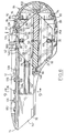
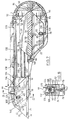
- a utility knife 10 has a manually holdable housing 12 with a front end 14 and a rear end 16.
- a blade magazine 18 is removably mounted in the housing 12 and is rotatable (in a manner which will be described later) about an axis parallel to the longitudinal axis of the housing 12 extending from the front end 14 to the rear end 16.
- the blade magazine 18 has a series of radially and longitudinally extending circumferentially spaced slot 20 for separately receiving thin blades 22, these slots 20 being open at both ends.
- the blades 22 are of a conventional kind with a trapezoidal shape having (see especially Fig. 7) a lower cutting edge 24 which meets the inclined end edges 26, 28 to form sharp cutting points 30, 32 at each end.
- the upper blade edge 34 is parallel to the lower cutting edge 24.
- the upper edge 34 has a recess 36 midway along its length, the recess 36 having a short initial straight portion 38 with parallel sides and a circular portion 40 at the inner end of the straight portion 38.
- the housing 12 also carries a slidable transport mechanism 42 which, as will also be described in more detail later, has a manually engageable actuator 44 projecting from the housing and slidable in a longitudinal direction between rear and front positions shown in Fig. 6 and 7 respectively.
- the blade magazine 18 has a rotatable body with two main parts 46, 48.
- the first part 46 has a hub-like end portion 50 with a series of radially and longitudinal extending circumferentially spaced slot-forming finger members 52.
- the finger members 52 extend in a longitudinal direction from the end portion 50 to the opposite end 54 of the first part 46.
- the finger member 52 extend longitudinally beyond the hub-like end portion 50 and their free ends form the opposite end 54 of the first magazine part 46.
- the second part 48 has a hub-like end portion 56 with a series of radially and longitudinal extending circumferentially spaced second slot-forming finger members 58 which extend in a longitudinal direction from the end portion 56 to the opposite end 60 of the second part 48.
- the finger members 58 extend longitudinally beyond the hub-like end portion 56 and their free ends form the opposite end 60 of the second magazine part 48.
- the first and second finger member 52, 58 each have a groove 61 midway along their radially outer surface, the groove 61 extending in a circumferential direction.
- the first magazine part 46 is assembled with the second part 48 by longitudinal movement of the first finger members 52 between the second finger members 58 to produce a blade receiving slot 20 between each adjacent pair of first and second finger members 52, 58.
- the end portions of the finger members 52 of the first magazine part 46 slide over and are supported by the hub-like end portion 56 of the second magazine part 48.
- the end portions of the second finger member 58 of the second magazine part 48 slide over and are supported by the hub-like end portion 50 of the first magazine part 46.
- the hub-like end portion 50 of the first magazine part 46 abuts the hub-like end portion 56 of the second magazine part 48, as shown in Fig. 6, and the circumferentially extending groove 61 in the finger members 52, 58 form a substantially continuous circumferential groove around the magazine 18 i.e. interrupted by the slots 20, see Fig. 5.
- the assembly of the magazine is completed by a blade-retaining ring 62, the ring 62 having a circumferential gap 64.
- the ring 62 is slid along the two assembled magazine parts 46, 48 from one end thereof until the ring 62 snaps into the circumferentially extending groove 60.
- the blades 22 are then loaded one at a time into the respective slots 20, with the blade-retaining ring 62 being moved around to position the gap 64 in alignment with the slot 20 into which a blade 22 is to be loaded.
- the circumferential width of the gap 64 in the blade-retaining ring 62 is equal to the spacing between the blade-receiving slots 20.
- a blade 22 is located in each slot 20 except one, namely the upper slot 20 in Fig. 5.
- the upper end of each blade 22 projects slightly above the circumferential periphery of the magazine 18 and the retaining ring 62 passes through the circular recesses 40 in each blade 22, thereby holding the blades 22 in the slots 20 with their lower cutting edges 24 slightly spaced from the hub-like end portion 50, 56 of the first and second magazine parts 46, 48.
- Each hub-like end portion 50, 56 has a longitudinally projecting stub shaft 66, 68 respectively of square section, and the blade-retaining ring 62 has a radially outwardly projecting retainer 70 a position diametrically opposite the circumferential gap 64.
- the purpose of the stub shaft 66, 68 and the retainer 70 will be described later.
- the housing 12 is formed in two longitudinally separable portions 72, 74, as most clearly shown in Fig. 2.
- the housing portion 72, 74 have interlocking engagement adjacent the front end 14 of the housing 12, see Figs. 2 and 3.
- the interlocking engagement is provided by a tongue and groove type connection, with the housing portion 72 providing a tongue 76 and the housing portion 74 having a groove 78.
- the tongue 76 on the housing portion 72 is slid in to the groove 78 in the housing portion 74 from the rear end of the groove 78.
- the two housing portions 72, 74 are mirror images of each other.
- the rear ends of the housing portions 72, 74 have external screw-threads 80, 82 respectively which combine to receive an internally threaded securing ring 84 which screws into engagement with the screw threads 80, 82 to secure the rear ends of the housing portions 72, 74 together.
- the securing ring 84 has a rear end cap 86 rotatably secured thereto, the end cap 86 having an annular shoulder 88 which snaps in to the rear end of securing ring 84 to effect the rotatable securing of the end cap 86 to the securing ring 84.
- the end cap 86 has a circumferential groove 90 rearwardly of the shoulder 88 which receives a tab 92 formed in securing ring 84.
- the circumferential groove 90 has detent slots 94 in its bottom surface, numbered as indicated in Fig. 2.
- the lower surface of the tab 92 on the securing ring 84 has a pip 96 (see Fig. 4) projecting downwardly therefrom.
- the pip 96 is engageable in the slots 94 in the end cap groove 90 to positively locate the end cap 86 in predetermined rotary positions relative to the securing ring 84 for a purpose which will be described later.
- the transport mechanism 42 has a main body member 100 with laterally extending wing portions 102, 104 which slide along longitudinally extending ledges 106, 108 on the housing portion 72, 74 respectively.
- a leg 110 extends downwardly from main body member 100 and has a transversely extending arcuate blade carrier arm 112 at its lower end.
- the blade carrier arm 112 can move in to the gap 64 in the blade retaining ring 62, and has a similar cross-section to the ring 62 except that the lower surface 114 of the blade carrier arm 112 is flat and located at a level which positions the surface 114 above the grooves 60 in the finger members 52, 58 of the first and second magazine parts 46, 48.
- the main body member 100 also has a rearward extension 116 carrying a post 118.
- a coil spring 120 surrounds and projects above the post 118.
- the lower end of the coil spring 120 is supported by the body member extension 116 and the upper end of the spring 120 carries the manually engageable actuator 44.
- the upper end of the spring 120 extends in to a recess 122 in the underside of actuator 44.
- the actuator 44 has a pair of laterally extending projections 124, 126 which normally slide beneath longitudinal extending downwardly facing shoulders 128, 130 in housing portion 72, 74 respectively for movement between forward and rear positions.
- the housing portion 74 has four longitudinally spaced recesses 132, 134, 136, 138, 139 extending upwardly from the shoulders 128, 130 and into each of which the actuator 44 can be pushed by the spring 120 to lock the transport mechanism 42 in any one of four predetermined positions as will be described in more detail later.
- the housing portion 72 has four similar recesses (not shown).
- the transport member 100 has a nose portion 140 at its leading end which is shaped to conform with the configuration of the front end 14 of the housing 12 when the transport member 100 is in its foremost position, and the housing portion 72, 74 form an opening 142 (see Fig. 3) to receive the nose portion 140.
- the housing portion 74 has a vertically spaced pair of guide members 144, 146 which guide the blade 22 during travel to the operative position as will also be described in more detail later.
- the housing portion 72 has similar guide members 145, 147.
- the housing portion 74 also has a semi-circular recess 148 which, together with a similar recess 149 in housing portion 72, form a bearing in which the forward stub shaft 66 of the magazine 18 can rotate.
- the rotatable end cap 86 has a square shaped recess 150 centrally located in its inner surface to receive the rear stub shaft 68 of the magazine 18 in relatively non-rotatable relationship.
- the housing portion 72, 74 have recesses 154, 156 at the rear end of their lower edges which form a slot 158 extending forwardly from the rear end 16 of housing 12 to receive the projection 70 on blade retaining ring 62, as will be described in more detail later.
- the two housing portions 72, 74 co-operate to provide a housing 12 with a rear portion 152 of bulbous shape in which the magazine 18 is located, the bulbous shape 152 having a size and shape for ergonomically comfortable holding in the hand.
- the end cap 86 is snapped out from the housing 12 by insertion of a suitable tool in slot 87 in securing ring 84, and a loaded magazine 18 is inserted in to the rear end of housing 12 so that the front stub shaft 66 enters the bearing formed by the recesses 148, 149 in the housing portions 74, 72 respectively. It will be noted that stub shaft 66 can freely rotate therein. Projection 70 on blade retaining ring 62 enters slot 158 at the bottom of the housing 12, and is thereby prevented from rotation. Securing ring 84 has a slot 89 aligned with slot 158 to enable projection 70 to pass through the securing ring 84. End cap 86 is then snapped back into securing ring 84.
- the actuator 44 is then depressed to release the projections 124, 126 from the recess 132 in the housing portion 74 and the corresponding recess in the housing portion 72 and is slid back to its rearmost position, i.e. adjacent the rear end of the housing 12, so that the blade carrier arm 112 on the transport member 100 moves in to the gap 64 in the blade retaining ring member 62, see Fig. 5.
- the projections 124, 126 are engaged in the rearmost recess 139 in the housing portion 74 and the corresponding recess in the housing portion 72 to lock the transport mechanism 42 in the rearmost or "docking" position.
- the end cap 86 is then rotated through one "click" i.e.
- the end cap 86 is provided with a finger grip 160 to enable such rotation to be easily effected.
- the actuator 44 is then slid forwardly, while being held down, to the foremost position until projections 124, 126 reach recess 132 in housing portion 174 and the corresponding recess in housing portion 72 at the forward end of the housing 12.
- the transport member 100 carries the blade 22 forwardly out of its slot 20 and to the operative position shown in Fig. 7, where the front part of the blade 22 projects from the front end of the housing 12.
- the blade 22 is guided by the guide members 144, 146 and 145, 147.
- the actuator 44 may be engaged in one of two more rearwardly positions defined by recesses 136, 138 in housing portion 74 and the corresponding recesses in housing portions 72.
- the actuator 44 is moyed back to recess 138 in housing portion 74 and the corresponding recess in housing portion 72. It will be noted that the blade 22 is prevented from rocking by engagement of its upper edge 34 with the lower surface 162 of a transport member 100, see Figs. 6 and 7.
- the actuator 46 is slid back to the rearmost position so that the blunt blade 22 is returned to its original slot 20.
- the magazine 18 is then rotated through a further increment rotation of the end cap 86 to the next number shown thereon, thereby causing the blunt blade 22 to be moved off blade carrier arm 112 and onto blade retaining member 62.
- a new blade 22 is moved on to the blade carrier arm 112 and can be moved to the operative position by depression and forward movement of the actuator 44.
Landscapes
- Engineering & Computer Science (AREA)
- Mechanical Engineering (AREA)
- Life Sciences & Earth Sciences (AREA)
- Forests & Forestry (AREA)
- Knives (AREA)
- Control And Other Processes For Unpacking Of Materials (AREA)
- Encapsulation Of And Coatings For Semiconductor Or Solid State Devices (AREA)
- Crushing And Pulverization Processes (AREA)
- Surgical Instruments (AREA)
- Making Paper Articles (AREA)
- Harvester Elements (AREA)
- Portable Nailing Machines And Staplers (AREA)
Applications Claiming Priority (3)
| Application Number | Priority Date | Filing Date | Title |
|---|---|---|---|
| US08/548,941 US5604984A (en) | 1995-10-26 | 1995-10-26 | Utility knife with rotary blade magazine |
| US548941 | 1995-10-26 | ||
| EP96933297A EP0858383B1 (de) | 1995-10-26 | 1996-10-21 | Allzweckmesser mit klingenmagazin |
Related Parent Applications (1)
| Application Number | Title | Priority Date | Filing Date |
|---|---|---|---|
| EP96933297A Division EP0858383B1 (de) | 1995-10-26 | 1996-10-21 | Allzweckmesser mit klingenmagazin |
Publications (3)
| Publication Number | Publication Date |
|---|---|
| EP0916458A2 true EP0916458A2 (de) | 1999-05-19 |
| EP0916458A3 EP0916458A3 (de) | 1999-08-11 |
| EP0916458B1 EP0916458B1 (de) | 2004-02-11 |
Family
ID=24191012
Family Applications (2)
| Application Number | Title | Priority Date | Filing Date |
|---|---|---|---|
| EP96933297A Expired - Lifetime EP0858383B1 (de) | 1995-10-26 | 1996-10-21 | Allzweckmesser mit klingenmagazin |
| EP99101506A Expired - Lifetime EP0916458B1 (de) | 1995-10-26 | 1996-10-21 | Klingenmagazin für Mehrzweckmesser |
Family Applications Before (1)
| Application Number | Title | Priority Date | Filing Date |
|---|---|---|---|
| EP96933297A Expired - Lifetime EP0858383B1 (de) | 1995-10-26 | 1996-10-21 | Allzweckmesser mit klingenmagazin |
Country Status (17)
| Country | Link |
|---|---|
| US (2) | US5604984A (de) |
| EP (2) | EP0858383B1 (de) |
| JP (1) | JP2000500667A (de) |
| CN (1) | CN1134325C (de) |
| AT (2) | ATE195455T1 (de) |
| AU (1) | AU703945B2 (de) |
| BR (1) | BR9611305A (de) |
| CA (1) | CA2235500C (de) |
| DE (2) | DE69631550T2 (de) |
| DK (2) | DK0858383T3 (de) |
| ES (2) | ES2152041T3 (de) |
| GR (1) | GR3034857T3 (de) |
| NZ (1) | NZ319546A (de) |
| PT (1) | PT858383E (de) |
| SI (1) | SI0858383T1 (de) |
| TW (1) | TW355695B (de) |
| WO (1) | WO1997015425A1 (de) |
Families Citing this family (37)
| Publication number | Priority date | Publication date | Assignee | Title |
|---|---|---|---|---|
| US5806189A (en) * | 1997-04-15 | 1998-09-15 | Bailey; Arthur | Utility knife |
| US5937522A (en) * | 1997-05-05 | 1999-08-17 | Warner-Lambert Company | Blade replacement device with used blade storage |
| US6101721A (en) | 1999-05-20 | 2000-08-15 | 1360314 Ontario Limited | Cutting/scraping tool |
| US6449850B1 (en) | 1999-08-13 | 2002-09-17 | The Stanley Works | Utility knife |
| US6330749B1 (en) * | 1999-08-14 | 2001-12-18 | Olympia Group, Inc. | Adjustable safety utility knife with easily removable blade holder |
| US6560873B1 (en) | 1999-11-12 | 2003-05-13 | Mel Wayne Ortner | Automatic safety knife |
| USD449771S1 (en) | 2000-03-17 | 2001-10-30 | Target Brands, Inc. | Knife handle |
| USD445662S1 (en) | 2000-10-21 | 2001-07-31 | Yin-Hae Huang | Artistic cutter |
| US6966113B2 (en) | 2001-07-23 | 2005-11-22 | Repetto Llc | Utility knife |
| USD511447S1 (en) | 2003-11-10 | 2005-11-15 | Irwin Industrial Tool Company | Utility knife |
| USD511288S1 (en) | 2003-11-10 | 2005-11-08 | Irwin Industrial Tool Company | Utility knife |
| USD508839S1 (en) | 2003-11-11 | 2005-08-30 | Irwin Industrial Tool Company | Utility knife |
| USD510010S1 (en) | 2003-11-11 | 2005-09-27 | Irwin Industrial Tool Company | Utility knife |
| USD524629S1 (en) * | 2004-03-17 | 2006-07-11 | Yuewei Wu | Tool |
| US20050283983A1 (en) * | 2004-06-23 | 2005-12-29 | Huang Yin H | Knife having automatically loading blade |
| US7434317B2 (en) * | 2004-09-23 | 2008-10-14 | Irwin Industrial Tool Company | Slide assembly device for a snap-off blade utility knife |
| USD559056S1 (en) * | 2005-04-01 | 2008-01-08 | Wise Robert W | Powered driver |
| US7194809B2 (en) * | 2005-04-18 | 2007-03-27 | Patents Holding Company | Quick release blade and knife |
| USD527602S1 (en) | 2005-06-13 | 2006-09-05 | Greenlee Textron Inc. | Retractable saw |
| US7516550B2 (en) * | 2005-06-13 | 2009-04-14 | Textron Innovations Inc. | Saw tool |
| US8245753B2 (en) * | 2006-01-05 | 2012-08-21 | Haemerle Richard R | Hand tools for applying masking tape and the like to various surfaces |
| GB0603908D0 (en) * | 2006-02-28 | 2006-04-05 | W A I Designs Ltd | Knife |
| WO2009058162A1 (en) * | 2007-10-31 | 2009-05-07 | Delillo Dominick D | Improved utility knife |
| USD606836S1 (en) * | 2007-10-31 | 2009-12-29 | Delillo Dominick D | Retractable utility knife |
| US20090165309A1 (en) * | 2007-12-27 | 2009-07-02 | Ibt Holding, Llc | Utility knife with blade release machanism |
| US20090223063A1 (en) * | 2008-03-10 | 2009-09-10 | Hallquist Todd E | Dual bladed utility knife |
| US20100107424A1 (en) * | 2008-10-14 | 2010-05-06 | Michael Garcia | Blade release mechanisms for utility knives |
| CN101704250B (zh) * | 2009-10-15 | 2011-12-28 | 杭州巨星科技股份有限公司 | 便于更换刀片的手动刀 |
| DE102010019571B4 (de) * | 2010-05-05 | 2020-05-20 | Martor Kg | Messer |
| US8689450B2 (en) * | 2011-04-29 | 2014-04-08 | Acme United Corporation | Knife having a reversible carriage |
| EP4374797A3 (de) | 2016-04-01 | 2024-08-14 | Merit Medical Systems, Inc. | Medizinische vorrichtungen zur abgabe von stopfen in hohlräume |
| US10398420B2 (en) * | 2016-04-04 | 2019-09-03 | Merit Medical Systems, Inc. | Medical plug delivery devices with a rotatable magazine and related components and methods |
| JP6718611B2 (ja) * | 2016-05-26 | 2020-07-08 | プラス株式会社 | カッター用の替刃及びカッター |
| US20170341251A1 (en) * | 2016-05-31 | 2017-11-30 | Acme United Corporation | Rotary Cutter |
| JP6736721B1 (ja) * | 2019-03-29 | 2020-08-05 | 株式会社貝印刃物開発センター | カッターナイフのホルダおよびカッターナイフ |
| US10800052B1 (en) | 2019-06-13 | 2020-10-13 | Repetto Llc | Utility knife, blade, and cartridge |
| US20250018589A1 (en) * | 2023-07-13 | 2025-01-16 | Stephen P. Souders | Pet Protector and Rescue Tool |
Citations (1)
| Publication number | Priority date | Publication date | Assignee | Title |
|---|---|---|---|---|
| GB2050227A (en) | 1979-05-25 | 1981-01-07 | Szabo Stephan L | Knives |
Family Cites Families (9)
| Publication number | Priority date | Publication date | Assignee | Title |
|---|---|---|---|---|
| US1436751A (en) * | 1920-01-20 | 1922-11-28 | Browning George | Safety razor |
| US2312453A (en) * | 1942-02-07 | 1943-03-02 | Gillette Safety Razor Co | Magazine for safety razor blades |
| US2784489A (en) * | 1954-03-10 | 1957-03-12 | Raymond E Reise | Utility blade holder |
| US4372362A (en) * | 1981-02-23 | 1983-02-08 | Ahn Min H | Tool |
| NL8103593A (nl) * | 1981-07-30 | 1983-02-16 | Schuler Jacob Pieter | Gereedschap met een aantal verwisselbare penvormige gereedschapselementen. |
| JPS6123973U (ja) * | 1984-07-16 | 1986-02-13 | エヌティー株式会社 | マガジン式カツタナイフ |
| US4552043A (en) * | 1984-12-14 | 1985-11-12 | Antonio Corona | Multiple bit screwdriver with improved chuck arrangement |
| US4552044A (en) * | 1985-02-12 | 1985-11-12 | Antonio Corona | Multibit screwdriver with improved bit insertion |
| DE8615168U1 (de) * | 1986-06-05 | 1986-07-17 | Chen, Jinn-Lih, Taipeh/T'ai-pei | Schraubendreher mit auswechselbaren Werkzeugspitzen |
-
1995
- 1995-10-26 US US08/548,941 patent/US5604984A/en not_active Expired - Lifetime
-
1996
- 1996-08-08 US US08/694,126 patent/US5727320A/en not_active Expired - Lifetime
- 1996-10-21 BR BR9611305-7A patent/BR9611305A/pt not_active Application Discontinuation
- 1996-10-21 WO PCT/CA1996/000696 patent/WO1997015425A1/en not_active Ceased
- 1996-10-21 AU AU72091/96A patent/AU703945B2/en not_active Ceased
- 1996-10-21 SI SI9630253T patent/SI0858383T1/xx unknown
- 1996-10-21 ES ES96933297T patent/ES2152041T3/es not_active Expired - Lifetime
- 1996-10-21 DE DE69631550T patent/DE69631550T2/de not_active Expired - Fee Related
- 1996-10-21 CA CA002235500A patent/CA2235500C/en not_active Expired - Fee Related
- 1996-10-21 EP EP96933297A patent/EP0858383B1/de not_active Expired - Lifetime
- 1996-10-21 ES ES99101506T patent/ES2215339T3/es not_active Expired - Lifetime
- 1996-10-21 EP EP99101506A patent/EP0916458B1/de not_active Expired - Lifetime
- 1996-10-21 DK DK96933297T patent/DK0858383T3/da active
- 1996-10-21 JP JP9516152A patent/JP2000500667A/ja not_active Ceased
- 1996-10-21 NZ NZ319546A patent/NZ319546A/en unknown
- 1996-10-21 DE DE69609852T patent/DE69609852T2/de not_active Expired - Fee Related
- 1996-10-21 DK DK99101506T patent/DK0916458T3/da active
- 1996-10-21 AT AT96933297T patent/ATE195455T1/de not_active IP Right Cessation
- 1996-10-21 PT PT96933297T patent/PT858383E/pt unknown
- 1996-10-21 AT AT99101506T patent/ATE259280T1/de not_active IP Right Cessation
- 1996-10-21 CN CNB961979089A patent/CN1134325C/zh not_active Expired - Fee Related
-
1998
- 1998-01-26 TW TW087101088A patent/TW355695B/zh active
-
2000
- 2000-11-15 GR GR20000402546T patent/GR3034857T3/el not_active IP Right Cessation
Patent Citations (1)
| Publication number | Priority date | Publication date | Assignee | Title |
|---|---|---|---|---|
| GB2050227A (en) | 1979-05-25 | 1981-01-07 | Szabo Stephan L | Knives |
Also Published As
| Publication number | Publication date |
|---|---|
| CN1134325C (zh) | 2004-01-14 |
| PT858383E (pt) | 2001-02-28 |
| EP0916458A3 (de) | 1999-08-11 |
| CA2235500C (en) | 2005-04-26 |
| SI0858383T1 (en) | 2001-02-28 |
| CA2235500A1 (en) | 1997-05-01 |
| US5727320A (en) | 1998-03-17 |
| EP0858383A1 (de) | 1998-08-19 |
| NZ319546A (en) | 1998-11-25 |
| DE69631550D1 (de) | 2004-03-18 |
| DK0858383T3 (da) | 2000-12-27 |
| EP0916458B1 (de) | 2004-02-11 |
| ATE259280T1 (de) | 2004-02-15 |
| DK0916458T3 (da) | 2004-06-14 |
| JP2000500667A (ja) | 2000-01-25 |
| CN1200693A (zh) | 1998-12-02 |
| EP0858383B1 (de) | 2000-08-16 |
| DE69609852D1 (de) | 2000-09-21 |
| DE69631550T2 (de) | 2004-12-30 |
| DE69609852T2 (de) | 2001-03-29 |
| ES2152041T3 (es) | 2001-01-16 |
| GR3034857T3 (en) | 2001-02-28 |
| US5604984A (en) | 1997-02-25 |
| AU703945B2 (en) | 1999-04-01 |
| ATE195455T1 (de) | 2000-09-15 |
| TW355695B (en) | 1999-04-11 |
| BR9611305A (pt) | 1999-12-28 |
| ES2215339T3 (es) | 2004-10-01 |
| WO1997015425A1 (en) | 1997-05-01 |
| AU7209196A (en) | 1997-05-15 |
Similar Documents
| Publication | Publication Date | Title |
|---|---|---|
| EP0916458B1 (de) | Klingenmagazin für Mehrzweckmesser | |
| US5819414A (en) | Double action folding knife | |
| US5960545A (en) | Utility knife with rotary blade magazine | |
| US9925674B2 (en) | Pocket cutter | |
| US4068375A (en) | Heavy duty retractable blade utility knife | |
| US7080455B1 (en) | Handheld kitchen scissor/knife appliance | |
| US8074362B2 (en) | Multi-blade utility knife | |
| US6263577B1 (en) | Automatic spring retractable utility knife | |
| US5689889A (en) | Knife with replaceable cutting element | |
| US3577637A (en) | Retractable blade knife | |
| US7739799B2 (en) | Combination utility and sporting knife | |
| US5502895A (en) | Folding blade pocket knife | |
| US6195896B1 (en) | Safety knife | |
| US4337576A (en) | Knife with retractable blade | |
| US6249973B1 (en) | Thinning razor | |
| US10259642B2 (en) | Blade dispenser | |
| US4823498A (en) | Line cutting tool and mounting base therefor | |
| US11752613B2 (en) | Manually operated convertible utility knife and scraper | |
| DE102012217550A1 (de) | Kreissägen-schutzsystem | |
| US20060053994A1 (en) | Rotary trimming apparatus | |
| WO1996005027A1 (en) | A safety knife or cutter | |
| US4858319A (en) | Apparatus for ensuring that a knife is opened in a desired orientation | |
| US20190248033A1 (en) | Combination scissors with cutting knife | |
| US20260077518A1 (en) | Multi-purpose detachable blade utility knife | |
| EP1079956A1 (de) | Klappmesser |
Legal Events
| Date | Code | Title | Description |
|---|---|---|---|
| PUAI | Public reference made under article 153(3) epc to a published international application that has entered the european phase |
Free format text: ORIGINAL CODE: 0009012 |
|
| AC | Divisional application: reference to earlier application |
Ref document number: 858383 Country of ref document: EP |
|
| AK | Designated contracting states |
Kind code of ref document: A2 Designated state(s): AT BE CH DE DK ES FI FR GB GR IE IT LI LU MC NL PT SE |
|
| AX | Request for extension of the european patent |
Free format text: AL PAYMENT 19990215;LT PAYMENT 19990215;LV PAYMENT 19990215;RO PAYMENT 19990215;SI PAYMENT 19990215 |
|
| PUAL | Search report despatched |
Free format text: ORIGINAL CODE: 0009013 |
|
| AK | Designated contracting states |
Kind code of ref document: A3 Designated state(s): AT BE CH DE DK ES FI FR GB GR IE IT LI LU MC NL PT SE |
|
| AX | Request for extension of the european patent |
Free format text: AL PAYMENT 19990215;LT PAYMENT 19990215;LV PAYMENT 19990215;RO PAYMENT 19990215;SI PAYMENT 19990215 |
|
| RIC1 | Information provided on ipc code assigned before grant |
Free format text: 6B 26B 5/00 A, 6B 25G 1/08 B |
|
| RAP1 | Party data changed (applicant data changed or rights of an application transferred) |
Owner name: THE NACK COMPANY LIMITED |
|
| RIN1 | Information on inventor provided before grant (corrected) |
Inventor name: SHEPERD, CHARLES G. Inventor name: FUNGER, EDWARD A. |
|
| 17P | Request for examination filed |
Effective date: 19991217 |
|
| RAP1 | Party data changed (applicant data changed or rights of an application transferred) |
Owner name: TECHTRONIC INDUSTRIES CO., LTD. |
|
| GRAH | Despatch of communication of intention to grant a patent |
Free format text: ORIGINAL CODE: EPIDOS IGRA |
|
| GRAS | Grant fee paid |
Free format text: ORIGINAL CODE: EPIDOSNIGR3 |
|
| GRAA | (expected) grant |
Free format text: ORIGINAL CODE: 0009210 |
|
| AC | Divisional application: reference to earlier application |
Ref document number: 0858383 Country of ref document: EP Kind code of ref document: P |
|
| AK | Designated contracting states |
Kind code of ref document: B1 Designated state(s): AT BE CH DE DK ES FI FR GB GR IE IT LI LU MC NL PT SE |
|
| AX | Request for extension of the european patent |
Extension state: AL LT LV RO SI |
|
| PG25 | Lapsed in a contracting state [announced via postgrant information from national office to epo] |
Ref country code: FI Free format text: LAPSE BECAUSE OF FAILURE TO SUBMIT A TRANSLATION OF THE DESCRIPTION OR TO PAY THE FEE WITHIN THE PRESCRIBED TIME-LIMIT Effective date: 20040211 |
|
| REG | Reference to a national code |
Ref country code: GB Ref legal event code: FG4D |
|
| REG | Reference to a national code |
Ref country code: CH Ref legal event code: EP |
|
| REG | Reference to a national code |
Ref country code: IE Ref legal event code: FG4D |
|
| REF | Corresponds to: |
Ref document number: 69631550 Country of ref document: DE Date of ref document: 20040318 Kind code of ref document: P |
|
| REG | Reference to a national code |
Ref country code: CH Ref legal event code: NV Representative=s name: RITSCHER & PARTNER AG PATENTANWAELTE |
|
| REG | Reference to a national code |
Ref country code: SE Ref legal event code: TRGR |
|
| PG25 | Lapsed in a contracting state [announced via postgrant information from national office to epo] |
Ref country code: GR Free format text: LAPSE BECAUSE OF FAILURE TO SUBMIT A TRANSLATION OF THE DESCRIPTION OR TO PAY THE FEE WITHIN THE PRESCRIBED TIME-LIMIT Effective date: 20040511 |
|
| REG | Reference to a national code |
Ref country code: DK Ref legal event code: T3 |
|
| LTIE | Lt: invalidation of european patent or patent extension |
Effective date: 20040211 |
|
| REG | Reference to a national code |
Ref country code: ES Ref legal event code: FG2A Ref document number: 2215339 Country of ref document: ES Kind code of ref document: T3 |
|
| PG25 | Lapsed in a contracting state [announced via postgrant information from national office to epo] |
Ref country code: LU Free format text: LAPSE BECAUSE OF NON-PAYMENT OF DUE FEES Effective date: 20041021 |
|
| ET | Fr: translation filed | ||
| PG25 | Lapsed in a contracting state [announced via postgrant information from national office to epo] |
Ref country code: MC Free format text: LAPSE BECAUSE OF NON-PAYMENT OF DUE FEES Effective date: 20041031 |
|
| PLBE | No opposition filed within time limit |
Free format text: ORIGINAL CODE: 0009261 |
|
| STAA | Information on the status of an ep patent application or granted ep patent |
Free format text: STATUS: NO OPPOSITION FILED WITHIN TIME LIMIT |
|
| 26N | No opposition filed |
Effective date: 20041112 |
|
| PGFP | Annual fee paid to national office [announced via postgrant information from national office to epo] |
Ref country code: ES Payment date: 20051004 Year of fee payment: 10 |
|
| PGFP | Annual fee paid to national office [announced via postgrant information from national office to epo] |
Ref country code: GB Payment date: 20051007 Year of fee payment: 10 |
|
| PGFP | Annual fee paid to national office [announced via postgrant information from national office to epo] |
Ref country code: FR Payment date: 20051012 Year of fee payment: 10 |
|
| PGFP | Annual fee paid to national office [announced via postgrant information from national office to epo] |
Ref country code: IE Payment date: 20051014 Year of fee payment: 10 |
|
| PGFP | Annual fee paid to national office [announced via postgrant information from national office to epo] |
Ref country code: DK Payment date: 20051020 Year of fee payment: 10 Ref country code: DE Payment date: 20051020 Year of fee payment: 10 |
|
| PGFP | Annual fee paid to national office [announced via postgrant information from national office to epo] |
Ref country code: SE Payment date: 20051025 Year of fee payment: 10 |
|
| PGFP | Annual fee paid to national office [announced via postgrant information from national office to epo] |
Ref country code: CH Payment date: 20051026 Year of fee payment: 10 |
|
| PGFP | Annual fee paid to national office [announced via postgrant information from national office to epo] |
Ref country code: AT Payment date: 20051027 Year of fee payment: 10 |
|
| PGFP | Annual fee paid to national office [announced via postgrant information from national office to epo] |
Ref country code: NL Payment date: 20051028 Year of fee payment: 10 |
|
| PGFP | Annual fee paid to national office [announced via postgrant information from national office to epo] |
Ref country code: BE Payment date: 20051117 Year of fee payment: 10 |
|
| PG25 | Lapsed in a contracting state [announced via postgrant information from national office to epo] |
Ref country code: AT Free format text: LAPSE BECAUSE OF NON-PAYMENT OF DUE FEES Effective date: 20061021 |
|
| PG25 | Lapsed in a contracting state [announced via postgrant information from national office to epo] |
Ref country code: SE Free format text: LAPSE BECAUSE OF NON-PAYMENT OF DUE FEES Effective date: 20061022 |
|
| PG25 | Lapsed in a contracting state [announced via postgrant information from national office to epo] |
Ref country code: IE Free format text: LAPSE BECAUSE OF NON-PAYMENT OF DUE FEES Effective date: 20061023 |
|
| PG25 | Lapsed in a contracting state [announced via postgrant information from national office to epo] |
Ref country code: LI Free format text: LAPSE BECAUSE OF NON-PAYMENT OF DUE FEES Effective date: 20061031 Ref country code: DK Free format text: LAPSE BECAUSE OF NON-PAYMENT OF DUE FEES Effective date: 20061031 Ref country code: CH Free format text: LAPSE BECAUSE OF NON-PAYMENT OF DUE FEES Effective date: 20061031 |
|
| PGFP | Annual fee paid to national office [announced via postgrant information from national office to epo] |
Ref country code: IT Payment date: 20061031 Year of fee payment: 11 |
|
| PG25 | Lapsed in a contracting state [announced via postgrant information from national office to epo] |
Ref country code: NL Free format text: LAPSE BECAUSE OF NON-PAYMENT OF DUE FEES Effective date: 20070501 Ref country code: DE Free format text: LAPSE BECAUSE OF NON-PAYMENT OF DUE FEES Effective date: 20070501 |
|
| REG | Reference to a national code |
Ref country code: CH Ref legal event code: PL |
|
| EUG | Se: european patent has lapsed | ||
| GBPC | Gb: european patent ceased through non-payment of renewal fee |
Effective date: 20061021 |
|
| NLV4 | Nl: lapsed or anulled due to non-payment of the annual fee |
Effective date: 20070501 |
|
| REG | Reference to a national code |
Ref country code: IE Ref legal event code: MM4A |
|
| REG | Reference to a national code |
Ref country code: FR Ref legal event code: ST Effective date: 20070629 |
|
| PG25 | Lapsed in a contracting state [announced via postgrant information from national office to epo] |
Ref country code: GB Free format text: LAPSE BECAUSE OF NON-PAYMENT OF DUE FEES Effective date: 20061021 |
|
| BERE | Be: lapsed |
Owner name: *TECHTRONIC INDUSTRIES CO. LTD Effective date: 20061031 |
|
| PG25 | Lapsed in a contracting state [announced via postgrant information from national office to epo] |
Ref country code: PT Free format text: LAPSE BECAUSE OF NON-PAYMENT OF DUE FEES Effective date: 20040711 |
|
| REG | Reference to a national code |
Ref country code: ES Ref legal event code: FD2A Effective date: 20061023 |
|
| PG25 | Lapsed in a contracting state [announced via postgrant information from national office to epo] |
Ref country code: FR Free format text: LAPSE BECAUSE OF NON-PAYMENT OF DUE FEES Effective date: 20061031 Ref country code: ES Free format text: LAPSE BECAUSE OF NON-PAYMENT OF DUE FEES Effective date: 20061023 |
|
| PG25 | Lapsed in a contracting state [announced via postgrant information from national office to epo] |
Ref country code: IT Free format text: LAPSE BECAUSE OF NON-PAYMENT OF DUE FEES Effective date: 20071021 Ref country code: BE Free format text: LAPSE BECAUSE OF FAILURE TO SUBMIT A TRANSLATION OF THE DESCRIPTION OR TO PAY THE FEE WITHIN THE PRESCRIBED TIME-LIMIT Effective date: 20061031 |