EP0916418A2 - Multipass wiredrawing machine provided with a device for improved adjustment and control of the tension of the wire being processed, particularly for drawing metal wires - Google Patents
Multipass wiredrawing machine provided with a device for improved adjustment and control of the tension of the wire being processed, particularly for drawing metal wires Download PDFInfo
- Publication number
- EP0916418A2 EP0916418A2 EP98120603A EP98120603A EP0916418A2 EP 0916418 A2 EP0916418 A2 EP 0916418A2 EP 98120603 A EP98120603 A EP 98120603A EP 98120603 A EP98120603 A EP 98120603A EP 0916418 A2 EP0916418 A2 EP 0916418A2
- Authority
- EP
- European Patent Office
- Prior art keywords
- die
- wire
- reel
- pulling
- wiredrawing machine
- Prior art date
- Legal status (The legal status is an assumption and is not a legal conclusion. Google has not performed a legal analysis and makes no representation as to the accuracy of the status listed.)
- Withdrawn
Links
Images

Classifications
-
- B—PERFORMING OPERATIONS; TRANSPORTING
- B21—MECHANICAL METAL-WORKING WITHOUT ESSENTIALLY REMOVING MATERIAL; PUNCHING METAL
- B21C—MANUFACTURE OF METAL SHEETS, WIRE, RODS, TUBES OR PROFILES, OTHERWISE THAN BY ROLLING; AUXILIARY OPERATIONS USED IN CONNECTION WITH METAL-WORKING WITHOUT ESSENTIALLY REMOVING MATERIAL
- B21C1/00—Manufacture of metal sheets, metal wire, metal rods, metal tubes by drawing
- B21C1/02—Drawing metal wire or like flexible metallic material by drawing machines or apparatus in which the drawing action is effected by drums
- B21C1/12—Regulating or controlling speed of drawing drums, e.g. to influence tension; Drives; Stop or relief mechanisms
-
- B—PERFORMING OPERATIONS; TRANSPORTING
- B21—MECHANICAL METAL-WORKING WITHOUT ESSENTIALLY REMOVING MATERIAL; PUNCHING METAL
- B21C—MANUFACTURE OF METAL SHEETS, WIRE, RODS, TUBES OR PROFILES, OTHERWISE THAN BY ROLLING; AUXILIARY OPERATIONS USED IN CONNECTION WITH METAL-WORKING WITHOUT ESSENTIALLY REMOVING MATERIAL
- B21C1/00—Manufacture of metal sheets, metal wire, metal rods, metal tubes by drawing
- B21C1/02—Drawing metal wire or like flexible metallic material by drawing machines or apparatus in which the drawing action is effected by drums
- B21C1/04—Drawing metal wire or like flexible metallic material by drawing machines or apparatus in which the drawing action is effected by drums with two or more dies operating in series
- B21C1/08—Drawing metal wire or like flexible metallic material by drawing machines or apparatus in which the drawing action is effected by drums with two or more dies operating in series in which the material does not slip on the drums
Definitions
- the present invention relates to a multipass wiredrawing machine provided with a device for adjusting and controlling the tension of the wire being processed, particularly adapted for drawing metal wires and the like.
- the invention relates to multiple soap and wet wiredrawing machines.
- drawing designates a kind of plastic cold working which consists in forcing the material, by pulling it, through the shaped hole of a die.
- the arrangement in sequence of a plurality of dies with holes having decreasing diameters allows to reduce the original diameter to the intended size.
- Traction is applied by a pulling reel arranged downstream of the die which, by turning, winds on itself a certain number of turns of the wire.
- the operation is repeated several times in succession by guiding the wire; accordingly, a plurality of dies are provided which are arranged in sequence, each die having a corresponding reel arranged downstream of it.
- the wire is thus guided from one reel to the next die with a consequent reduction in diameter between one transfer and the next.
- the drawing action must be applied so that the wire being processed, by generating friction on the pulling reel actuated by an electric motor, allows said reel to pull it (with a capstan effect), wind it and then guide it to the next reel.
- the ideal situation would be to provide direct transfer of the wire from one reel to the next.
- the essential requirement for correct operation is that the rotation rate of the individual reels must strictly match the tension variations of the wire that leaves the respective dies, adapting the rate to the elongations that the wire undergoes in passing through the various dies.
- the latter are movable elements onto which the wire being processed is guided. Any variations in the elongation of the wire cause angular or straight-line movements of these elements which, by means of position transducers such as inductive transducers (potentiometers, encoders, etcetera) control and correct the speed of the corresponding motor, thus maintaining uninterrupted processing.
- position transducers such as inductive transducers (potentiometers, encoders, etcetera) control and correct the speed of the corresponding motor, thus maintaining uninterrupted processing.
- Another solution that has been adopted recently in order to produce wiredrawing machines whose operation is as close as possible to the above described optimum condition entails controlling the speed of the individual reels, detecting wire tension variations both in the portion between the die and the reel and between the reel and the next die.
- the aim of the present invention is therefore to provide a multipass wiredrawing machine provided with a device for adjusting and controlling the wire being processed which allows to maintain direct traction of the wire without having to resort to devices for accumulating the wire or to dancer rolls and the like.
- an object of the present invention is to provide a multipass wiredrawing machine provided with a device for adjusting and controlling wire traction which allows to maintain a constant tension on the wire in the critical traction portion between the die and the pulling reel and in the critical release portion between the reel and the next die.
- Another object of the present invention is to provide a multipass wiredrawing machine which allows to draw wires made of different materials by means of the same machine.
- Another object of the present invention is to provide a multipass wiredrawing machine which has a minimal number of constructive parts.
- Another object of the present invention is to provide a multipass wiredrawing machine which is highly reliable, relatively easy to manufacture and at competitive costs.
- a multipass wiredrawing machine particularly for drawing metal wires which comprises a plurality of reels for pulling a wire that exits from a corresponding die, said reels being arranged in sequence to wind the wire that exits from the die and guide it to a next die, characterized in that each pulling reel is fixed, while the corresponding die can move with respect to the corresponding pulling reel, in order to maintain a substantially constant length for a portion of wire with respect to the corresponding pulling reel and allow the length of the portion of wire to vary with respect to the preceding pulling reel, so as to provide constant adjustment of the tension of the wire between the die and the reel and between the reel and the next die.
- the reference numeral 10 designates a wire being processed, which passes through a die 1 and is wound onto a cylindrical body of a pulling reel 3.
- V1 designates the speed of the wire 10 in the portion between the die 1 and the reel 3 and V1' designates the speed of the wire 10 in the portion between the pulling reel 3 and the next die 1.
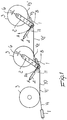
- Figure 1 illustrates a first embodiment of the wiredrawing machine according to the present invention, which comprises a plurality of pulling reels 3 and dies 1, each of which is supported by a movable arm 2 which is pivoted to the center of the corresponding pulling reel 3.
- Each movable arm 2 is actuated by corresponding actuation means 4 which are rigidly coupled to the frame of the wiredrawing machine.
- Each die 1 can therefore move along an arc A-B, consequently adjusting the tension of the wire 10.
- Figure 2 illustrates a second embodiment of the wiredrawing machine according to the present invention, wherein, differently from the first embodiment, the movable arm 2 is pivoted externally with respect to the center of the pulling reel 3, for example tangent to the traction line of the wire 10, or in any case in a position which allows to avoid variations in the length of the portion of wire 10 between the die 1 and the pulling reel 3.
- the movement of the movable arm 2 and of the corresponding die 1 activates sensor means 6, such as a position sensor 6, which is conveniently provided for example by means of an inductive transducer, a potentiometer, a proximity sensor, an encoder etcetera and acts on the elements that control the motor that drives the reel 3 involved, adjusting its rotation rate.
- sensor means 6 such as a position sensor 6, which is conveniently provided for example by means of an inductive transducer, a potentiometer, a proximity sensor, an encoder etcetera and acts on the elements that control the motor that drives the reel 3 involved, adjusting its rotation rate.
- the movement of the die 1 along the arc A-B ensures that the synchronization speed is maintained, so that the various dies 1 remain at a median equilibrium position, determined by a central point of the sensor means 6, i.e., a point in which the sensor means detect no movement of the die and therefore emit no signal to slow down or speed up the pulling reel.
- the movement of the die 1 in either direction along the arc A-B activates, by virtue of the sensor means 6, a signal which, by acting on adjustment means (not shown) of the corresponding motor that drives the pulling reel 3 adjusts its rotation rate, restoring synchronization among the various pulling reels 3 and accordingly returning the die 1 at said median equilibrium point.
- the wiredrawing machine according to the invention fully achieves the intended aim, since it allows to obtain a constant adjustment of the tension between the die and the reel and the next die without the aid of dancer rolls or sensors or similar systems for detecting wire tension changes.
- the materials used may be any according to the requirements and the state of the art.
Abstract
Description
- The present invention relates to a multipass wiredrawing machine provided with a device for adjusting and controlling the tension of the wire being processed, particularly adapted for drawing metal wires and the like.
- In particular, the invention relates to multiple soap and wet wiredrawing machines.
- The term "drawing" designates a kind of plastic cold working which consists in forcing the material, by pulling it, through the shaped hole of a die. The arrangement in sequence of a plurality of dies with holes having decreasing diameters allows to reduce the original diameter to the intended size.
- It is known that in order to draw metal wires the wire passes through a die where its cross-section is reduced by plastic deformation.
- Traction is applied by a pulling reel arranged downstream of the die which, by turning, winds on itself a certain number of turns of the wire.
- In the case of multipass wiredrawing machines, the operation is repeated several times in succession by guiding the wire; accordingly, a plurality of dies are provided which are arranged in sequence, each die having a corresponding reel arranged downstream of it.
- The wire is thus guided from one reel to the next die with a consequent reduction in diameter between one transfer and the next.
- The drawing action must be applied so that the wire being processed, by generating friction on the pulling reel actuated by an electric motor, allows said reel to pull it (with a capstan effect), wind it and then guide it to the next reel.
- Since drawing is performed without removing material, i.e., with a constant volume, the ratio between the cross-section and the speed of the wire becomes particularly important and must be kept constant for each pass through the various dies and respective reels.
- Accordingly, at every reduction in the diameter of the wire, the wire becomes longer and accordingly each reel has progressively higher rotation rates in order to wind an increasingly longer wire.
- The ideal situation would be to provide direct transfer of the wire from one reel to the next.
- The essential requirement for correct operation is that the rotation rate of the individual reels must strictly match the tension variations of the wire that leaves the respective dies, adapting the rate to the elongations that the wire undergoes in passing through the various dies.
- In practice, this theoretically ideal condition is difficult to achieve because it is difficult to precisely control the rotation rates of the individual motors that drive the reels and because of the variables that come into play during processing, such as die wear etcetera.
- In order to obviate these drawbacks, wiredrawing machines have been used which accumulate wire between one reel and the next; more recently, machines provided with a dancer roll or bend detector have been used.
- The latter are movable elements onto which the wire being processed is guided. Any variations in the elongation of the wire cause angular or straight-line movements of these elements which, by means of position transducers such as inductive transducers (potentiometers, encoders, etcetera) control and correct the speed of the corresponding motor, thus maintaining uninterrupted processing.
- The above described conventional solution, however, has the drawback that they bend the wire around the movable elements, with bending which is sometimes too extreme to obtain optimum metallurgical characteristics of the wire.
- Drawbacks also arise due to difficulties in constructing wiredrawing machines that adopt these solutions, in addition to difficulties in threading the machines.
- Another solution that has been adopted recently in order to produce wiredrawing machines whose operation is as close as possible to the above described optimum condition entails controlling the speed of the individual reels, detecting wire tension variations both in the portion between the die and the reel and between the reel and the next die.
- The position of the reels and of the dies is fixed; accordingly, since there are no moving elements, control of the speed of the motors of the reels produces variable tensions on the wire in the portion between the reel and the next die.
- The aim of the present invention is therefore to provide a multipass wiredrawing machine provided with a device for adjusting and controlling the wire being processed which allows to maintain direct traction of the wire without having to resort to devices for accumulating the wire or to dancer rolls and the like.
- Within the scope of this aim, an object of the present invention is to provide a multipass wiredrawing machine provided with a device for adjusting and controlling wire traction which allows to maintain a constant tension on the wire in the critical traction portion between the die and the pulling reel and in the critical release portion between the reel and the next die.
- Another object of the present invention is to provide a multipass wiredrawing machine which allows to draw wires made of different materials by means of the same machine.
- Another object of the present invention is to provide a multipass wiredrawing machine which has a minimal number of constructive parts.
- Another object of the present invention is to provide a multipass wiredrawing machine which is highly reliable, relatively easy to manufacture and at competitive costs.
- This aim, these objects and others which will become apparent hereinafter are achieved by a multipass wiredrawing machine particularly for drawing metal wires which comprises a plurality of reels for pulling a wire that exits from a corresponding die, said reels being arranged in sequence to wind the wire that exits from the die and guide it to a next die, characterized in that each pulling reel is fixed, while the corresponding die can move with respect to the corresponding pulling reel, in order to maintain a substantially constant length for a portion of wire with respect to the corresponding pulling reel and allow the length of the portion of wire to vary with respect to the preceding pulling reel, so as to provide constant adjustment of the tension of the wire between the die and the reel and between the reel and the next die.
- Further characteristics and advantages of the invention will become apparent from the description of preferred but not exclusive embodiments of the multipass wiredrawing machine according to the invention, illustrated only by way of non-limitative example in the accompanying drawings, wherein:
- Figure 1 is a schematic view of a first embodiment of the multipass wiredrawing machine according to the present invention; and
- Figure 2 is a schematic view of a second embodiment of the multipass wiredrawing machine according to the present invention.
-
- With reference to the above figures, and particularly to Figure 1, the
reference numeral 10 designates a wire being processed, which passes through a die 1 and is wound onto a cylindrical body of apulling reel 3. - V1 designates the speed of the
wire 10 in the portion between the die 1 and thereel 3 and V1' designates the speed of thewire 10 in the portion between thepulling reel 3 and the next die 1. - The respective speeds V2, V2', V3 and V3' are designated likewise for the
successive reels 3. - For correct operation of the wiredrawing machine, the following conditions must occur during operation:
- -- at the speed V, the tension between the die 1 and
the
reel 3 must remain constant; - -- in the portion between the
reel 3 and the next die 1, the speed V' must be equal to the speed V in the preceding portion. -
- In order to maintain a constant tension of the
wire 10 in all the portions of the wiredrawing machine, there must be synchronization among one pulling reel, the pulling reel that precedes it and the one that follows it, so that there are no variations in the speeds V and V' (where V and V' here designate the speeds, for a generic reel, in the portions before and after the reel, respectively). - Figure 1 illustrates a first embodiment of the wiredrawing machine according to the present invention, which comprises a plurality of pulling
reels 3 and dies 1, each of which is supported by a movable arm 2 which is pivoted to the center of thecorresponding pulling reel 3. - Each movable arm 2 is actuated by corresponding actuation means 4 which are rigidly coupled to the frame of the wiredrawing machine.
- Each die 1 can therefore move along an arc A-B, consequently adjusting the tension of the
wire 10. - Figure 2 illustrates a second embodiment of the wiredrawing machine according to the present invention, wherein, differently from the first embodiment, the movable arm 2 is pivoted externally with respect to the center of the
pulling reel 3, for example tangent to the traction line of thewire 10, or in any case in a position which allows to avoid variations in the length of the portion ofwire 10 between the die 1 and thepulling reel 3. - For both embodiments, the movement of the movable arm 2 and of the corresponding die 1 activates sensor means 6, such as a
position sensor 6, which is conveniently provided for example by means of an inductive transducer, a potentiometer, a proximity sensor, an encoder etcetera and acts on the elements that control the motor that drives thereel 3 involved, adjusting its rotation rate. - The movement of the die 1 along the arc A-B ensures that the synchronization speed is maintained, so that the various dies 1 remain at a median equilibrium position, determined by a central point of the sensor means 6, i.e., a point in which the sensor means detect no movement of the die and therefore emit no signal to slow down or speed up the pulling reel.
- The movement of the die 1 in either direction along the arc A-B activates, by virtue of the sensor means 6, a signal which, by acting on adjustment means (not shown) of the corresponding motor that drives the
pulling reel 3 adjusts its rotation rate, restoring synchronization among thevarious pulling reels 3 and accordingly returning the die 1 at said median equilibrium point. - In practice it has been observed that the wiredrawing machine according to the invention fully achieves the intended aim, since it allows to obtain a constant adjustment of the tension between the die and the reel and the next die without the aid of dancer rolls or sensors or similar systems for detecting wire tension changes.
- The wiredrawing machine thus conceived is susceptible of numerous modifications and variations, all of which are within the scope of the inventive concept.
- All the details may furthermore be replaced with other technically equivalent elements. Thus, for example, the various figures illustrate a multiple wiredrawing machine with reels having a horizontal axis; however, it is also possible to use reels having a vertical axis, superimposed horizontal reels, stepped vertical reels, etcetera.
- For both embodiments shown in Figures 1 and 2 it is possible to provide, upstream of the dies 1, respective guiding pulleys 11 which are rigidly coupled to the die holder boxes and allow the wire to enter the dies in perfect alignment with the center of the dies.
- In Figure 2, the center of rotation of the arm 2 can be shifted with respect to the tangent to the
reel 3. - Furthermore, the movement of the dies is described as occurring along an arc, but it is possible to provide for a different movement, provided that the above described wire tension conditions are maintained.
- In practice, the materials used, so long as they are compatible with the specific use, as well as the dimensions, may be any according to the requirements and the state of the art.
- The disclosures in Italian Patent Application No. MI97A002514 from which this application claims priority are incorporated herein by reference.
- Where technical features mentioned in any claim are followed by reference signs, those reference signs have been included for the sole purpose of increasing the intelligibility of the claims and accordingly, such reference signs do not have any limiting effect on the interpretation of each element identified by way of example by such reference signs.
Claims (8)
- A multipass wiredrawing machine particularly for drawing metal wires which comprises a plurality of reels for pulling a wire that exits from a corresponding die, said reels being arranged mutually in sequence to wind the wire that exits from the die and guide it to a next die, characterized in that each pulling reel is fixed, while the corresponding die can move with respect to the corresponding pulling reel, in order to maintain a substantially constant length for a portion of wire with respect to the corresponding pulling reel and allow the length of the portion of wire to vary with respect to the preceding pulling reel, so as to provide constant adjustment of the tension of the wire between the die and the reel and between the reel and the next die.
- The wiredrawing machine according to claim 1, characterized in that each die moves along an arc with respect to the corresponding pulling reel.
- The multipass wiredrawing machine according to claim 2, characterized in that each die is connected to a corresponding movable arm actuated by actuation means.
- The wiredrawing machine according to claim 3, characterized in that each movable arm is pivoted to the rotation axis of the respective pulling reel, the arc of the movement of said die being centered at a point where said movable arm is pivoted.
- The wiredrawing machine according to claim 3, characterized in that each movable arm is pivoted externally with respect to a center of the corresponding pulling reel.
- The wiredrawing machine according to claim 3, characterized in that each movable arm is pivoted externally with respect to a center of the corresponding pulling reel, tangent to a traction line of said wire, in order to maintain a constant length of the portion of wire between the die and the corresponding pulling reel, the arc of the movement of said die being centered at a point where said movable arm is pivoted.
- The wiredrawing machine according to claim 1, characterized in that it comprises means for detecting the position of said reel which are adapted to actuate means for adjusting a rotation rate of said reel as a function of the detected position.
- The wiredrawing machine according to claim 1, characterized in that it comprises a guiding pulley which is arranged upstream of each die in order to center the insertion of the wire into the respective die.
Applications Claiming Priority (2)
| Application Number | Priority Date | Filing Date | Title |
|---|---|---|---|
| ITMI972514 | 1997-11-11 | ||
| IT97MI002514A IT1296099B1 (en) | 1997-11-11 | 1997-11-11 | MULTI-STEP DRAWING MACHINE EQUIPPED WITH A DEVICE FOR IMPROVED ADJUSTMENT AND CONTROL OF THE TENSION OF THE WIRE IN PROCESS |
Publications (2)
| Publication Number | Publication Date |
|---|---|
| EP0916418A2 true EP0916418A2 (en) | 1999-05-19 |
| EP0916418A3 EP0916418A3 (en) | 2000-01-05 |
Family
ID=11378189
Family Applications (1)
| Application Number | Title | Priority Date | Filing Date |
|---|---|---|---|
| EP98120603A Withdrawn EP0916418A3 (en) | 1997-11-11 | 1998-10-30 | Multipass wiredrawing machine provided with a device for improved adjustment and control of the tension of the wire being processed, particularly for drawing metal wires |
Country Status (3)
| Country | Link |
|---|---|
| US (1) | US6164112A (en) |
| EP (1) | EP0916418A3 (en) |
| IT (1) | IT1296099B1 (en) |
Cited By (2)
| Publication number | Priority date | Publication date | Assignee | Title |
|---|---|---|---|---|
| CN110681708A (en) * | 2019-09-24 | 2020-01-14 | 常州市明通金属复合材料有限公司 | Combined six-continuous drawing machine for drawing copper-clad aluminum wires |
| WO2021036713A1 (en) * | 2020-03-18 | 2021-03-04 | 河南理工大学 | Relative sliding-less superfine metal or alloy wire drawing apparatus |
Families Citing this family (8)
| Publication number | Priority date | Publication date | Assignee | Title |
|---|---|---|---|---|
| US7188503B2 (en) * | 2004-10-29 | 2007-03-13 | The Goodyear Tire + Rubber Company | Fine wire drawing machine |
| CN101804427B (en) * | 2010-04-12 | 2011-08-31 | 无锡平盛科技有限公司 | Wire-stripping guide wheel mechanism on inverted quincuncial wire-rewinding machine |
| US9676016B2 (en) * | 2013-09-23 | 2017-06-13 | Manchester Copper Products, Llc | Systems and methods for drawing materials |
| CN107214203A (en) * | 2017-06-30 | 2017-09-29 | 张家港市龙晟机械制造有限公司 | A kind of multi-pass is without the wet drawing drawing process that skids |
| CN113070357B (en) * | 2021-03-24 | 2022-12-02 | 天津市金桥焊材集团股份有限公司 | Speed regulation control method for wire drawing machine |
| CN113578983A (en) * | 2021-07-23 | 2021-11-02 | 苏闽(张家港)新型金属材料科技有限公司 | Preparation method of 25-34 mu m superfine ultrahigh-strength and toughness diamond wire bus |
| CN114310523B (en) * | 2021-12-30 | 2023-10-20 | 广西贵港和乐门业有限公司 | Manual wire drawing machine of door leaf of tensioning fast |
| CN114888104B (en) * | 2022-05-27 | 2023-07-04 | 江苏锦瑞金属制品有限公司 | Wire drawing machine with tension adjusting mechanism for metal material processing |
Citations (1)
| Publication number | Priority date | Publication date | Assignee | Title |
|---|---|---|---|---|
| US1915722A (en) * | 1930-09-11 | 1933-06-27 | American Steel & Wire Co | Wire drawing machine |
Family Cites Families (6)
| Publication number | Priority date | Publication date | Assignee | Title |
|---|---|---|---|---|
| US935564A (en) * | 1904-03-11 | 1909-09-28 | Hugh L Thompson | Wire-drawing machine. |
| US1178331A (en) * | 1915-05-04 | 1916-04-04 | Harry A Marvin | Wire-drawing machine. |
| US1354336A (en) * | 1919-03-13 | 1920-09-28 | Waterbury Farrel Foundry & Mac | Wire-drawing machine |
| DE959904C (en) * | 1953-12-19 | 1957-03-14 | Herborn Berkenhoff & Drebes A | Non-slip wire drawing machine, the drums of which have two drawing surfaces separated by a flange |
| DE2131874C3 (en) * | 1971-06-26 | 1984-07-19 | Benteler-Werke Ag, 4794 Schloss Neuhaus | Device for reducing pipe strings |
| DE2445945A1 (en) * | 1974-09-26 | 1976-04-15 | Diehl Fa | METHOD AND DEVICE FOR DRAWING STAND ADJUSTMENT ON WIRE DRAWING MACHINES |
-
1997
- 1997-11-11 IT IT97MI002514A patent/IT1296099B1/en active IP Right Grant
-
1998
- 1998-10-30 EP EP98120603A patent/EP0916418A3/en not_active Withdrawn
- 1998-11-02 US US09/184,056 patent/US6164112A/en not_active Expired - Lifetime
Patent Citations (1)
| Publication number | Priority date | Publication date | Assignee | Title |
|---|---|---|---|---|
| US1915722A (en) * | 1930-09-11 | 1933-06-27 | American Steel & Wire Co | Wire drawing machine |
Cited By (2)
| Publication number | Priority date | Publication date | Assignee | Title |
|---|---|---|---|---|
| CN110681708A (en) * | 2019-09-24 | 2020-01-14 | 常州市明通金属复合材料有限公司 | Combined six-continuous drawing machine for drawing copper-clad aluminum wires |
| WO2021036713A1 (en) * | 2020-03-18 | 2021-03-04 | 河南理工大学 | Relative sliding-less superfine metal or alloy wire drawing apparatus |
Also Published As
| Publication number | Publication date |
|---|---|
| US6164112A (en) | 2000-12-26 |
| IT1296099B1 (en) | 1999-06-09 |
| ITMI972514A1 (en) | 1999-05-11 |
| EP0916418A3 (en) | 2000-01-05 |
Similar Documents
| Publication | Publication Date | Title |
|---|---|---|
| NL2004285C2 (en) | Method and apparatus for rewinding welding wire. | |
| US7640774B2 (en) | Wire drawing machine and method | |
| US6164112A (en) | Adjustment and tension control device for a multipass wire drawing machine | |
| JP4996949B2 (en) | Slot storage device for supporting optical fiber and slot storage method for supporting optical fiber | |
| US5392977A (en) | Coil material supply apparatus for an intermittent feed device | |
| JP3771918B2 (en) | Wire drawing machine | |
| US6018975A (en) | Multipass wiredrawing machine with wire tension control device | |
| HU910931D0 (en) | Slippageless straight line wire-drawing machine with synchronized tangential unwinding drums following each other | |
| JPH04270020A (en) | Device for measuring and cutting electric wire | |
| CN1021384C (en) | Method for tape tension adjustment | |
| CN111874746A (en) | Torque sensor and take-up machine | |
| WO2003051547A1 (en) | Continuing rolling apparatus for wire | |
| CN104870350A (en) | Continuous wire supplying device and continuous wire supplying method | |
| US2793672A (en) | Method of close coiling sheathed spring wire | |
| CN110316609B (en) | Calculation method for paying-off and winding diameter of basket type rope combining machine | |
| US5505067A (en) | Non-contact double-block speed controller | |
| JP4781919B2 (en) | Wire material winding method and core wire winding method | |
| KR100405906B1 (en) | Apparatus for suppressing strip tension hunting in horizontal looper | |
| CN212799063U (en) | Torque sensor and take-up machine | |
| CN110899349B (en) | Wire drawing machine | |
| JPS6245769Y2 (en) | ||
| RU2176944C2 (en) | Apparatus for coiling continuously cast rods | |
| JP4359163B2 (en) | Wire rod feeder for wire rod processing machine | |
| JP2001087810A (en) | Device for continuously coiling wire rod | |
| CN116475254A (en) | Continuous wire drawing machine with wire rod preloading device |
Legal Events
| Date | Code | Title | Description |
|---|---|---|---|
| PUAI | Public reference made under article 153(3) epc to a published international application that has entered the european phase |
Free format text: ORIGINAL CODE: 0009012 |
|
| AK | Designated contracting states |
Kind code of ref document: A2 Designated state(s): IT |
|
| AX | Request for extension of the european patent |
Free format text: AL;LT;LV;MK;RO;SI |
|
| PUAL | Search report despatched |
Free format text: ORIGINAL CODE: 0009013 |
|
| AK | Designated contracting states |
Kind code of ref document: A3 Designated state(s): AT BE CH CY DE DK ES FI FR GB GR IE IT LI LU MC NL PT SE |
|
| AX | Request for extension of the european patent |
Free format text: AL;LT;LV;MK;RO;SI |
|
| 17P | Request for examination filed |
Effective date: 20000629 |
|
| AKX | Designation fees paid |
Free format text: IT |
|
| REG | Reference to a national code |
Ref country code: DE Ref legal event code: 8566 |
|
| 17Q | First examination report despatched |
Effective date: 20020419 |
|
| STAA | Information on the status of an ep patent application or granted ep patent |
Free format text: STATUS: THE APPLICATION IS DEEMED TO BE WITHDRAWN |
|
| 18D | Application deemed to be withdrawn |
Effective date: 20021030 |