EP0915260A1 - Method of fastening a guiding device on a support, guiding device obtained by this method and marking apparatus comprising such a device - Google Patents
Method of fastening a guiding device on a support, guiding device obtained by this method and marking apparatus comprising such a device Download PDFInfo
- Publication number
- EP0915260A1 EP0915260A1 EP98420199A EP98420199A EP0915260A1 EP 0915260 A1 EP0915260 A1 EP 0915260A1 EP 98420199 A EP98420199 A EP 98420199A EP 98420199 A EP98420199 A EP 98420199A EP 0915260 A1 EP0915260 A1 EP 0915260A1
- Authority
- EP
- European Patent Office
- Prior art keywords
- guide member
- opening
- support
- guide
- bar
- Prior art date
- Legal status (The legal status is an assumption and is not a legal conclusion. Google has not performed a legal analysis and makes no representation as to the accuracy of the status listed.)
- Granted
Links
- 238000000034 method Methods 0.000 title claims abstract description 12
- 229920005989 resin Polymers 0.000 claims abstract description 27
- 239000011347 resin Substances 0.000 claims abstract description 27
- 230000000379 polymerizing effect Effects 0.000 claims abstract 2
- 210000000056 organ Anatomy 0.000 claims description 3
- 239000011248 coating agent Substances 0.000 claims description 2
- 238000000576 coating method Methods 0.000 claims description 2
- 230000003100 immobilizing effect Effects 0.000 claims description 2
- 238000011065 in-situ storage Methods 0.000 claims description 2
- 239000007787 solid Substances 0.000 claims description 2
- 239000011229 interlayer Substances 0.000 claims 2
- 239000002966 varnish Substances 0.000 description 8
- 238000003754 machining Methods 0.000 description 4
- 238000006116 polymerization reaction Methods 0.000 description 3
- 238000012423 maintenance Methods 0.000 description 2
- 239000004593 Epoxy Substances 0.000 description 1
- 238000005266 casting Methods 0.000 description 1
- 238000004140 cleaning Methods 0.000 description 1
- 238000006073 displacement reaction Methods 0.000 description 1
- 230000000694 effects Effects 0.000 description 1
- 238000004519 manufacturing process Methods 0.000 description 1
- 239000000463 material Substances 0.000 description 1
- 229920000647 polyepoxide Polymers 0.000 description 1
- 229920005749 polyurethane resin Polymers 0.000 description 1
- 238000007789 sealing Methods 0.000 description 1
Images

Classifications
-
- F—MECHANICAL ENGINEERING; LIGHTING; HEATING; WEAPONS; BLASTING
- F16—ENGINEERING ELEMENTS AND UNITS; GENERAL MEASURES FOR PRODUCING AND MAINTAINING EFFECTIVE FUNCTIONING OF MACHINES OR INSTALLATIONS; THERMAL INSULATION IN GENERAL
- F16C—SHAFTS; FLEXIBLE SHAFTS; ELEMENTS OR CRANKSHAFT MECHANISMS; ROTARY BODIES OTHER THAN GEARING ELEMENTS; BEARINGS
- F16C29/00—Bearings for parts moving only linearly
- F16C29/12—Arrangements for adjusting play
-
- F—MECHANICAL ENGINEERING; LIGHTING; HEATING; WEAPONS; BLASTING
- F16—ENGINEERING ELEMENTS AND UNITS; GENERAL MEASURES FOR PRODUCING AND MAINTAINING EFFECTIVE FUNCTIONING OF MACHINES OR INSTALLATIONS; THERMAL INSULATION IN GENERAL
- F16B—DEVICES FOR FASTENING OR SECURING CONSTRUCTIONAL ELEMENTS OR MACHINE PARTS TOGETHER, e.g. NAILS, BOLTS, CIRCLIPS, CLAMPS, CLIPS OR WEDGES; JOINTS OR JOINTING
- F16B11/00—Connecting constructional elements or machine parts by sticking or pressing them together, e.g. cold pressure welding
- F16B11/006—Connecting constructional elements or machine parts by sticking or pressing them together, e.g. cold pressure welding by gluing
- F16B11/008—Connecting constructional elements or machine parts by sticking or pressing them together, e.g. cold pressure welding by gluing of tubular elements or rods in coaxial engagement
-
- F—MECHANICAL ENGINEERING; LIGHTING; HEATING; WEAPONS; BLASTING
- F16—ENGINEERING ELEMENTS AND UNITS; GENERAL MEASURES FOR PRODUCING AND MAINTAINING EFFECTIVE FUNCTIONING OF MACHINES OR INSTALLATIONS; THERMAL INSULATION IN GENERAL
- F16C—SHAFTS; FLEXIBLE SHAFTS; ELEMENTS OR CRANKSHAFT MECHANISMS; ROTARY BODIES OTHER THAN GEARING ELEMENTS; BEARINGS
- F16C29/00—Bearings for parts moving only linearly
- F16C29/02—Sliding-contact bearings
-
- Y—GENERAL TAGGING OF NEW TECHNOLOGICAL DEVELOPMENTS; GENERAL TAGGING OF CROSS-SECTIONAL TECHNOLOGIES SPANNING OVER SEVERAL SECTIONS OF THE IPC; TECHNICAL SUBJECTS COVERED BY FORMER USPC CROSS-REFERENCE ART COLLECTIONS [XRACs] AND DIGESTS
- Y10—TECHNICAL SUBJECTS COVERED BY FORMER USPC
- Y10T—TECHNICAL SUBJECTS COVERED BY FORMER US CLASSIFICATION
- Y10T403/00—Joints and connections
- Y10T403/32—Articulated members
- Y10T403/32606—Pivoted
- Y10T403/32861—T-pivot, e.g., wrist pin, etc.
- Y10T403/32877—Pin is integral with or secured to inner member
-
- Y—GENERAL TAGGING OF NEW TECHNOLOGICAL DEVELOPMENTS; GENERAL TAGGING OF CROSS-SECTIONAL TECHNOLOGIES SPANNING OVER SEVERAL SECTIONS OF THE IPC; TECHNICAL SUBJECTS COVERED BY FORMER USPC CROSS-REFERENCE ART COLLECTIONS [XRACs] AND DIGESTS
- Y10—TECHNICAL SUBJECTS COVERED BY FORMER USPC
- Y10T—TECHNICAL SUBJECTS COVERED BY FORMER US CLASSIFICATION
- Y10T403/00—Joints and connections
- Y10T403/32—Articulated members
- Y10T403/32606—Pivoted
- Y10T403/32861—T-pivot, e.g., wrist pin, etc.
- Y10T403/32893—T-pivot, e.g., wrist pin, etc. including distinct pin retainer
-
- Y—GENERAL TAGGING OF NEW TECHNOLOGICAL DEVELOPMENTS; GENERAL TAGGING OF CROSS-SECTIONAL TECHNOLOGIES SPANNING OVER SEVERAL SECTIONS OF THE IPC; TECHNICAL SUBJECTS COVERED BY FORMER USPC CROSS-REFERENCE ART COLLECTIONS [XRACs] AND DIGESTS
- Y10—TECHNICAL SUBJECTS COVERED BY FORMER USPC
- Y10T—TECHNICAL SUBJECTS COVERED BY FORMER US CLASSIFICATION
- Y10T403/00—Joints and connections
- Y10T403/32—Articulated members
- Y10T403/32606—Pivoted
- Y10T403/32951—Transverse pin or stud
- Y10T403/32967—Attached to or integral with one member
-
- Y—GENERAL TAGGING OF NEW TECHNOLOGICAL DEVELOPMENTS; GENERAL TAGGING OF CROSS-SECTIONAL TECHNOLOGIES SPANNING OVER SEVERAL SECTIONS OF THE IPC; TECHNICAL SUBJECTS COVERED BY FORMER USPC CROSS-REFERENCE ART COLLECTIONS [XRACs] AND DIGESTS
- Y10—TECHNICAL SUBJECTS COVERED BY FORMER USPC
- Y10T—TECHNICAL SUBJECTS COVERED BY FORMER US CLASSIFICATION
- Y10T403/00—Joints and connections
- Y10T403/47—Molded joint
- Y10T403/472—Molded joint including mechanical interlock
Definitions
- the present invention relates to a fixing method a guide member on a support.
- the quality of expected geometry is not always obtained after assembly executed.
- the marking device is susceptible deform under the effect of the stresses exerted by the clamping occurring during the corresponding machining, or still under the influence of the tools' rump efforts ensuring this machining.
- the subject of the invention is a method of fixing of a guide member on a support which ensures a precise positioning of these different elements by compared to others, while generating mechanical forces limits.
- the invention relates to a method of fixing of a guide member on a support, in which cleaning in the support at least one opening suitable for receiving one end of the guide member, and we introduce this end in the opening, characterized in that one realizes opening in substantially transverse dimensions greater than those of the end which is received there, we places the guide member in the precise position it must occupy, we thus delimit an intermediate space between the outer periphery of the end and the walls opposite the opening, we fill this intermediate space with a resin polymerizable and said resin is polymerized so to secure the end relative to the opening.
- the relative positioning phase of the guide member and the opening in which it is inserted can be implemented using simple mechanical means, for example example a timing system. This therefore does not induce efforts important likely to alter the geometry of the whole the device once made.
- the polymerizable resin introduced into the intermediate space formed between the guide member and the opening which receives it ensures a reliable fixing of each guide member on the support.
- the invention also relates to a device for guidance obtained according to the above method, comprising at least a guide member fixed on a support, each end of this member being housed in a corresponding opening formed in the support, characterized in that this opening has transverse dimensions substantially greater than those of the end of the guide member, a sheath formed of a solid state polymerizable resin being cast in situ between the outer periphery of this end and the walls next to the opening.
- the invention finally relates to a marking device comprising at least one guide device as described above.
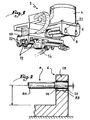
- the marking device shown in Figure 1 and designated as a whole by reference 2 includes, so known per se, a fixed frame 4 comprising two flanges 6 in look supporting two bars 8 constituting organs of guide, for the displacement along the axis of these bars of a first carriage 10.
- the latter is also provided with two guide bars 12, the two pairs of bars 8, 12 being arranged substantially at right angles.
- the bars 12 guide a second carriage 14 on which is intended to be attached a marking head not shown.
- the two carriages 10, 14 therefore constitute the drive mechanism of the marking device, and ensure positioning of the marking head in two directions orthogonal to each other.
- the respective training of the two carriages 10, 14 is provided, in a manner known per se, by by means of electric motors not shown.
- each bar 8 comprises a cylindrical middle part 8A terminated by two cylindrical ends 8B of larger diameter, of which only one is shown.
- the bar 8 is intended to be fixed to the rim 6 by its ends 8B.
- Each of the latter is received at a cylindrical through opening 16, formed in the rim 6.
- This opening 16 has a transverse dimension, namely a diameter D, which is substantially greater than that of the end 8B, namely its diameter d .
- each end 8B within of the opening 16 it first of all introduce each end 8B within of the opening 16, then position them relatively according to the shape of the marking device once done.
- the bar 8 is maintained by relative to a reference surface of the frame 4, in this case a 6A base rectified beforehand, at distances and according to appropriate guidance. This maintenance can be ensured, by example, by a system of shims. It should be noted that in the example shown, the bar 8 and the opening 16 are not rigorously coaxial.
- the outer periphery of the end 8B defines, with the walls of the opening 16 opposite, an intermediate space Roughly annular. While holding the 8 bar and the ledge 6 in their relative positions mentioned above, we then fills this intermediate space 20 with a resin polymerizable, for example an epoxy or polyurethane resin. We may also plan to use other types of materials equivalent curable.
- a resin polymerizable for example an epoxy or polyurethane resin.
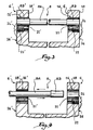
- Figures 3 and 4 illustrate a first variant of realization of the invention.
- Bar 8 which is mounted in two openings 16, 16 'formed in the flanges 6, 6' in look of the frame 4, is similar to that shown in the figure 2.
- the outer periphery of the ends 8B of this bar 8 is covered with a non-stick varnish which allows them to slide freely in the sleeves 21, 21 'of resin filling the designated intermediate spaces by reference 20 in Figure 2.
- the mounting of a new bar on its support is particularly easy. It should first of all be covered the ends with the non-stick varnish. Then, we introduces one end of this bar within the sheath 21 'whose access is not prohibited by the presence of a screw. We then slide this first end in this sheath 21 '. We then pass the part middle, then we slide the second end of this closed off. The latter is then precisely positioned in an axial direction, due to the presence of the screw 22 against which the first end of this new bar comes to a stop. In addition, the latter is perfectly positioned in a transverse direction, due to the presence of the resin shells 21, 21 ′ having served to immobilize the first bar 8. The subjection in translation the new bar is made by replacing the screw 22 ', removed for disassembly of the first bar 8, at its location original.
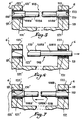
- Figures 5 to 7 illustrate a second variant of realization of the invention.
- the bar 108 differs from that 8 shown in FIGS. 2 to 4, in meaning that each of its ends 108B, 108B 'is provided a distal chamfer 110, 110 ', so that they widen in direction of the middle part 108A.
- Resin sheaths, interposed between the walls of the openings 16, 16 'and the outer periphery of the ends 108B, 108B 'of the bar, with a view to subjugating the latter in relation to the carriage 6, are therefore no longer generally annular like this was the case previously.
- the ends 108B, 108B 'of the bar 108 are covered with a non-stick varnish, this bar is perfectly immobilized both transversely thanks to the annular parts 122, 122 'of the resin sheaths, as well only axially since these ends abut against the pockets 123, 123 'which obstruct the movement of the closed off.
- each end of the new bar is positioned in a transverse direction, thanks to the presence of the annular parts 122, 122 ′ at the into which the ends are introduced.
- the axial positioning of the entire new bar is provided by the pocket 123 'which was not destroyed during the disassembly of the first bar, pocket against which the new bar comes to a stop.
- the subjugation in translation of this new bar is made by pouring a new resin pocket into the location 124 of the pocket 123 previously destroyed.
- Figures 8 and 9 illustrate two additional variants of the invention.
- the bar 208 presents a constant diameter over its entire length.
- the outer periphery of its ends 208B, 208B ' is not covered with a non-stick varnish, but is surrounded by an annular ring 228, for example metallic.
- the bar 308 also has a diameter constant over its entire length. Its ends 308B, 308B ' include a chamfer 310. The outer periphery of its ends 308B, 308B 'is not covered with non-stick varnish, but is surrounded by a chamfered ring 328 of which the profile is conjugated with that of the ends 308B, 308B '.
- the bar 308 is sealed to support 6 while being provided with these rings 328, by casting sheaths of resins 321, 321 'analogous to those represented in FIGS. 5 to 7.
Abstract
Description
La présente invention a trait à un procédé de fixation d'un organe de guidage sur un support.The present invention relates to a fixing method a guide member on a support.
Il est nécessaire de positionner chaque organe de guidage par rapport aux portées qui le reçoivent, de manière extrêmement minutieuse. A cet effet, il est connu d'usiner les surfaces de portées évoquées ci-dessus, selon des cotes précises par rapport à une surface de référence du support, de manière à réaliser des ouvertures dans lesquelles les organes de guidage sont introduites avec un jeu réduit.It is necessary to position each guide member compared to the staves that receive it, in an extremely meticulous. For this purpose, it is known to machine the bearing surfaces mentioned above, according to dimensions precise with respect to a reference surface of the support, so as to make openings in which the organs guides are introduced with reduced play.
Un tel procédé présente cependant certains inconvénients. En effet, il implique un usinage extrêmement minutieux, ce qui induit un temps et un coût de fabrication élevés.However, such a method has certain drawbacks. Indeed, it involves extremely meticulous machining, which induces a high manufacturing time and cost.
De plus, dans le cas d'appareils dont la tenue mécanique est faible, comme des appareils de marquage, la qualité de géométrie espérée n'est pas toujours obtenue une fois l'assemblage réalisé. En effet, l'appareil de marquage est susceptible de se déformer sous l'effet des contraintes exercées par le bridage intervenant durant l'usinage correspondant, ou bien encore sous l'influence des efforts de croupe des outils assurant cet usinage.In addition, in the case of devices whose mechanical strength is weak, like marking devices, the quality of expected geometry is not always obtained after assembly executed. Indeed, the marking device is susceptible deform under the effect of the stresses exerted by the clamping occurring during the corresponding machining, or still under the influence of the tools' rump efforts ensuring this machining.
Afin de pallier les inconvénients de l'art antérieur évoqués ci-dessus, l'invention a pour objet un procédé de fixation d'un organe de guidage sur un support qui assure un positionnement précis de ces différents éléments les uns par rapport aux autres, tout en générant des efforts mécaniques limités.In order to overcome the drawbacks of the prior art mentioned above, the subject of the invention is a method of fixing of a guide member on a support which ensures a precise positioning of these different elements by compared to others, while generating mechanical forces limits.
A cet effet, l'invention a pour objet un procédé de fixation d'un organe de guidage sur un support, dans lequel on ménage dans le support au moins une ouverture propre à recevoir une extrémité de l'organe de guidage, et on introduit cette extrémité dans l'ouverture, caractérisé en ce qu'on réalise l'ouverture selon des dimensions transversales substantiellement supérieures à celles de l'extrémité qui y est reçue, on place l'organe de guidage dans la position précise qu'il doit occuper, on délimite ainsi un espace intercalaire entre la périphérie extérieure de l'extrémité et les parois en regard de l'ouverture, on remplit cet espace intercalaire avec une résine polymérisable et l'on fait polymériser ladite résine de façon à assujettir l'extrémité par rapport à l'ouverture.To this end, the invention relates to a method of fixing of a guide member on a support, in which cleaning in the support at least one opening suitable for receiving one end of the guide member, and we introduce this end in the opening, characterized in that one realizes opening in substantially transverse dimensions greater than those of the end which is received there, we places the guide member in the precise position it must occupy, we thus delimit an intermediate space between the outer periphery of the end and the walls opposite the opening, we fill this intermediate space with a resin polymerizable and said resin is polymerized so to secure the end relative to the opening.
Le procédé conforme à l'invention permet de réaliser les objectifs précédemment mentionnés.The process according to the invention makes it possible to carry out the previously mentioned objectives.
En effet, étant donné que chaque ouverture est réalisée selon des dimensions transversales nettement supérieures à celles de l'extrémité de l'organe de guidage qui y est reçu, l'usinage correspondant ne requiert aucune précision particulière. Il peut donc être réalisé de manière nettement plus rapide que ceux mis en oeuvre dans les procédés de l'art antérieur, et n'implique pas de bridage des différents éléments.Indeed, since each opening is made according to transverse dimensions clearly greater than those of the end of the guide member which is received there, the corresponding machining does not require any particular precision. It can therefore be carried out much more clearly. faster than those implemented in the art processes previous, and does not involve clamping of the different elements.
La phase de positionnement relatif de l'organe de guidage et de l'ouverture dans laquelle ce dernier est inséré, peut être mise en oeuvre grâce à des moyens mécaniques simples, par exemple un système de calage. Ceci n'induit donc pas d'efforts importants susceptibles d'altérer la géométrie de l'ensemble de l'appareil une fois réalisé.The relative positioning phase of the guide member and the opening in which it is inserted, can be implemented using simple mechanical means, for example example a timing system. This therefore does not induce efforts important likely to alter the geometry of the whole the device once made.
Enfin, la résine polymérisable introduite au sein de l'espace intercalaire ménagé entre l'organe de guidage et l'ouverture qui le reçoit, assure une fixation fiable de chaque organe de guidage sur le support.Finally, the polymerizable resin introduced into the intermediate space formed between the guide member and the opening which receives it, ensures a reliable fixing of each guide member on the support.
L'invention a également pour objet un dispositif de guidage obtenu selon le procédé ci-dessus, comprenant au moins un organe de guidage fixé sur un support, chaque extrémité de cet organe étant logée dans une ouverture correspondante ménagée dans le support, caractérisé en ce que cette ouverture a des dimensions transversales substantiellement supérieures à celles de l'extrémité de l'organe de guidage, un fourreau formé d'une résine polymérisable à l'état solide étant coulé in-situ entre la périphérie extérieure de cette extrémité et les parois en regard de l'ouverture.The invention also relates to a device for guidance obtained according to the above method, comprising at least a guide member fixed on a support, each end of this member being housed in a corresponding opening formed in the support, characterized in that this opening has transverse dimensions substantially greater than those of the end of the guide member, a sheath formed of a solid state polymerizable resin being cast in situ between the outer periphery of this end and the walls next to the opening.
Le dispositif de guidage peut comporter une ou plusieurs des caractéristiques suivantes :
- l'organe de guidage peut coulisser axialement par rapport au fourreau et il est prévu, au voisinage de chaque extrémité de l'organe de guidage, des moyens amovibles d'immobilisation axiale de cette extrémité par rapport au support ;
- les moyens d'immobilisation amovibles comprennent au moins un élément de fixation vissé dans une paroi du support au voisinage de l'ouverture, une partie dudit élément débordant au niveau de l'ouverture de manière à retenir en butée l'extrémité de l'organe de guidage ;
- l'extrémité de l'organe de guidage comporte un décrochement, les moyens d'immobilisation amovibles comprenant une poche de la résine, disposée au voisinage du décrochement ;
- la périphérie extérieure des extrémités de l'organe de guidage est entourée au moyen d'une bague éventuellement chanfreinée ;
- un revêtement anti-adhésif est disposé à la périphérie extérieure des extrémités de l'organe de guidage ;
- les extrémités de l'organe de guidage sont reliées par une partie médiane de plus faible section.
- the guide member can slide axially relative to the sheath and there is provided, in the vicinity of each end of the guide member, removable means for axially immobilizing this end relative to the support;
- the removable immobilization means comprise at least one fixing element screwed into a wall of the support in the vicinity of the opening, a part of said element projecting at the level of the opening so as to retain the end of the member in abutment guiding;
- the end of the guide member comprises a recess, the removable immobilization means comprising a pocket of the resin, disposed in the vicinity of the recess;
- the outer periphery of the ends of the guide member is surrounded by means of a possibly chamfered ring;
- a non-stick coating is arranged at the outer periphery of the ends of the guide member;
- the ends of the guide member are connected by a middle part of smaller section.
L'invention a enfin pour objet un appareil de marquage comportant au moins un dispositif de guidage tel que décrit ci-dessus.The invention finally relates to a marking device comprising at least one guide device as described above.
L'invention va être décrite ci-dessous, en référence aux dessins annexés, donnés uniquement à titre d'exemple non limitatif et dans lesquels :
- la figure 1 est une vue schématique en perspective d'un appareil de marquage conforme à l'invention ;
- la figure 2 est une vue en coupe schématique illustrant la phase de positionnement d'un organe de guidage de l'appareil de marquage de la figure 1 ;
- les figures 3 et 4 sont des vues schématiques en coupe illustrant une première variante de réalisation, dans deux phases de montage d'un organe de guidage ;
- les figures 5 à 7 sont des vues analogues aux figures 3 et 4, illustrant une seconde variante de réalisation de l'invention, dans trois phases de montage d'un organe de guidage ;
- les figures 8 et 9 sont des vues analogues aux figures 3 à 7, illustrant deux variantes supplémentaires de l'invention.
- Figure 1 is a schematic perspective view of a marking apparatus according to the invention;
- Figure 2 is a schematic sectional view illustrating the positioning phase of a guide member of the marking apparatus of Figure 1;
- Figures 3 and 4 are schematic sectional views illustrating a first alternative embodiment, in two stages of mounting a guide member;
- Figures 5 to 7 are views similar to Figures 3 and 4, illustrating a second alternative embodiment of the invention, in three stages of mounting a guide member;
- Figures 8 and 9 are views similar to Figures 3 to 7, illustrating two additional variants of the invention.
L'appareil de marquage représenté à la figure 1 et désigné
dans son ensemble par la référence 2 comprend, de manière
connue en soi, un bâti fixe 4 comprenant deux rebords 6 en
regard supportant deux barres 8 constituant des organes de
guidage, en vue du déplacement selon l'axe de ces barres d'un
premier chariot 10. Ce dernier est également muni de deux
barres 12 de guidage, les deux paires de barres 8, 12 étant
disposées sensiblement à angle droit.The marking device shown in Figure 1 and designated
as a whole by
Les barres 12 assurent le guidage d'un second chariot 14
sur lequel est destinée à être rapportée une tête de marquage
non représentée. Les deux chariots 10, 14 constituent donc le
mécanisme d'entraínement de l'appareil de marquage, et assurent
le positionnement de la tête de marquage selon deux directions
orthogonales entre elles. L'entraínement respectif des deux
chariots 10, 14 est assuré, de manière connue en soi, par
l'intermédiaire de moteurs électriques non représentés.The
La fixation de chaque barre sur son support respectif va
être décrite dans ce qui suit, en référence aux figures 2 à 9.
Dans ces dernières, il sera uniquement fait référence à la
fixation des barres 8 sur les rebords 6 du bâti 4. La fixation
des barres 12 sur le premier chariot 10 est bien évidemment
analogue.The fixing of each bar on its respective support will
be described in the following, with reference to Figures 2 to 9.
In the latter, only reference will be made to the
fixing the
Comme le montre la figure 2, chaque barre 8 comprend une
partie médiane 8A cylindrique terminée par deux extrémités
cylindriques 8B de plus grand diamètre, dont une seule est
représentée. La barre 8 est destinée à être fixée sur le rebord
6 par ses extrémités 8B. Chacune de ces dernières est reçue au
niveau d'une ouverture traversante cylindrique 16, ménagée dans
le rebord 6. Cette ouverture 16 présente une dimension transversale,
à savoir un diamètre D, qui est substantiellement
supérieure à celle de l'extrémité 8B, à savoir son diamètre d.As shown in FIG. 2, each
En vue de la fixation de la barre 8 sur le rebord 6, il
convient tout d'abord d'introduire chaque extrémité 8B au sein
de l'ouverture 16, puis de les positionner relativement selon
la conformation que doit présenter le dispositif de marquage
une fois réalisé. A cet effet, la barre 8 est maintenue par
rapport à une surface de référence du bâti 4, en l'occurrence
une embase 6A rectifiée au préalable, à des distances et selon
des orientations appropriées. Ce maintien peut être assuré, par
exemple, par un système de cales. Il est à noter que, dans
l'exemple représenté, la barre 8 et l'ouverture 16 ne sont pas
rigoureusement coaxiales.For the purpose of fixing the
Etant donné que les diamètres respectifs de l'extrémité 8B
de la barre 8 et de l'ouverture 16 sont sensiblement différents,
la périphérie extérieure de l'extrémité 8B définit, avec
les parois de l'ouverture 16 en regard, un espace intercalaire
20 à peu près annulaire. Tout en maintenant la barre 8 et le
rebord 6 dans leurs positions relatives évoquées ci-dessus, on
remplit alors cet espace intercalaire 20 au moyen d'une résine
polymérisable, par exemple une résine époxy ou polyuréthane. On
peut également prévoir d'utiliser d'autres types de matériaux
durcissables équivalents.Since the respective diameters of the
On assure ensuite la polymérisation de cette résine, de
manière connue en soi. Une fois cette polymérisation achevée,
la résine solidifiée remplissant l'espace intercalaire 20 forme
un fourreau au sein duquel est maintenue l'extrémité 8B de la
barre. De la sorte, la barre 8 et le rebord 6 sont parfaitement
assujettis l'un par rapport à l'autre, selon des dimensions et
des orientations correspondant à l'agencement visé du dispositif
de marquage. Il est alors possible d'ôter le système de
calage ayant contribué au maintien relatif de la barre et du
chariot durant le temps de polymérisation de la résine.This polymerization is then ensured,
in a manner known per se. Once this polymerization is complete,
the solidified resin filling the
Les figures 3 et 4 illustrent une première variante de
réalisation de l'invention. La barre 8, qui est montée dans
deux ouvertures 16, 16' ménagées dans les rebords 6, 6' en
regard du bâti 4, est analogue à celle représentée à la figure
2. Toutefois, la périphérie extérieure des extrémités 8B de
cette barre 8 est recouverte au moyen d'un vernis anti-adhésif
qui leur permet de coulisser librement dans les fourreaux 21,
21' de résine remplissant les espaces intercalaires désignés
par la référence 20 à la figure 2.Figures 3 and 4 illustrate a first variant of
realization of the invention.
Deux vis 22, 22' sont engagées dans chaque rebord 6, 6'.
Leur tête 24, 24' est disposée contre la face extérieure 26,
26' de chaque rebord 6, 6' et s'étend au voisinage de chaque
ouverture 16, 16' de sorte que chaque extrémité 8B, 8B' de la
barre 8 vienne en butée contre la tête de ces vis. La barre 8
est donc immobilisée transversalement, au niveau de ses
extrémités 8B, 8B', par l'intermédiaire des fourreaux 21, 21'
de résine. De plus, cette barre 8 est immobilisée axialement
selon deux sens opposés, grâce à la tête 24, 24' des vis 22,
22'.Two
Dans le cas où il se révèle nécessaire de changer la barre
8, par exemple en vue de sa réparation, il convient d'enlever
l'une des vis qui l'immobilise axialement, en l'occurrence la
vis 8' dans l'exemple représenté à la figure 4. Grâce à la
présence du vernis anti-adhésif, l'extrémité 8B' est libre de
coulisser axialement au sein du fourreau 21', de même que
l'extrémité opposée 8B. Etant donné que la partie médiane 8A de
la barre 8 est de plus faible section que les extrémités, il
est superflu de la recouvrir d'un tel vernis anti-adhésif en
vue d'assurer son passage au travers du fourreau 21'. Il est à
noter que, durant cette opération de démontage, la seconde vis
22 reste engagée dans le rebord 6.In the event that it is necessary to change the
Le montage d'une nouvelle barre sur son support est
particulièrement aisé. Il convient tout d'abord d'en recouvrir
les extrémités au moyen du vernis anti-adhésif. Puis, on
introduit l'une des extrémités de cette barre au sein du
fourreau 21' dont l'accès n'est pas interdit par la présence
d'une vis. On fait ensuite coulisser cette première extrémité
dans ce fourreau 21'. On y fait ensuite passer la partie
médiane, puis on y fait coulisser la seconde extrémité de cette
barre. Cette dernière est alors positionnée de manière précise
dans une direction axiale, du fait de la présence de la vis 22
contre laquelle la première extrémité de cette nouvelle barrre
vient en butée. De plus, cette dernière est parfaitement
positionnée selon une direction transversale, du fait de la
présence des fourereaux de résine 21, 21' ayant servi à
immobiliser la première barre 8. L'assujettissement en translation
de la nouvelle barre est réalisé en replaçant la vis 22',
ôtée en vue du démontage de la première barre 8, à son emplacement
originel.The mounting of a new bar on its support is
particularly easy. It should first of all be covered
the ends with the non-stick varnish. Then, we
introduces one end of this bar within the
sheath 21 'whose access is not prohibited by the presence
of a screw. We then slide this first end
in this sheath 21 '. We then pass the part
middle, then we slide the second end of this
closed off. The latter is then precisely positioned
in an axial direction, due to the presence of the
Grâce à ce mode de réalisation, il n'est nécessaire ni de
détruire la résine de scellement, ni d'utiliser l'outillage
particulier ayant servi au positionnement et à l'assujettissement
de la première barre 8.Thanks to this embodiment, it is not necessary either to
destroy the sealing resin or use the tools
individual used for positioning and securing
from the
Les figures 5 à 7 illustrent une seconde variante de
réalisation de l'invention. Conformément à cette variante, la
barre 108 diffère de celle 8 représentée aux figures 2 à 4, en
ce sens que chacune de ses extrémités 108B, 108B' est pourvue
d'un chanfrein distal 110, 110', de sorte qu'elles s'évasent en
direction de la partie médiane 108A. Les fourreaux de résine,
intercalés entre les parois des ouvertures 16, 16' et la
périphérie extérieure des extrémités 108B, 108B' de la barre,
en vue de l'assujettissement de cette dernière par rapport au
chariot 6, ne sont donc plus globalement annulaires comme cela
était le cas précédemment. Ces fourreaux 121, 121' comprennent
une partie annulaire 122, 122' s'étendant au voisinage des
parois cylindriques de chaque ouverture 16, 16', ainsi qu'une
poche 123, 123' disposée au voisinage de chaque chanfrein 110,
110'. Bien que les extrémités 108B, 108B' de la barre 108
soient recouvertes d'un vernis anti-adhésif, cette barre est
parfaitement immobilisée à la fois transversalement grâce aux
parties annulaires 122, 122' des fourreaux de résine, ainsi
qu'axialement puisque ces extrémités viennent en butée contre
les poches 123, 123' qui font obstacle au déplacement de la
barre.Figures 5 to 7 illustrate a second variant of
realization of the invention. According to this variant, the
Dans le cas où l'on désire démonter cette barre 108, par
exemple en vue de sa réparation, il est nécessaire de casser
l'une des poches de résine, en l'occurrence la poche 123 comme
cela est représenté à la figure 6. L'extrémité correspondante
108B de la barre 108 est alors libre de coulisser axialement au
sein de la partie annulaire 122 du fourreau 121, du fait de la
présence du vernis anti-adhésif. On fait ensuite passer la
partie médiane 108A de plus faible section au travers de cette
partie annulaire 122, puis on y fait enfin coulisser la seconde
extrémité 108B'.If it is desired to disassemble this
L'opération consistant à monter une nouvelle barre sur le
rebord 6 s'opère de manière analogue, en introduisant cette
nouvelle barre depuis l'ouverture 16 dépourvue de poche de
résine 123. L'extrémité de cette nouvelle barre, introduite au
préalable par cette ouverture 16, vient alors en butée contre
la poche 123' non détruite, comme le montre la figure 7.The operation of mounting a new bar on the
Grâce à l'invention, on confère au positionnement donné à
cette nouvelle barre le même degré de précision qu'à celui de
la première barre 108. En effet, chaque extrémité de la
nouvelle barre est positionnée selon une direction transversale,
grâce à la présence des parties annulaires 122, 122' au
sein desquels les extrémités sont introduites. De plus, le
positionnement axial de l'ensemble de la nouvelle barre est
assuré par la poche 123' qui n'a pas été détruite lors du
démontage de la première barre, poche contre laquelle la
nouvelle barre vient en butée.Thanks to the invention, the positioning given to
this new bar the same degree of precision as that of
the
L'assujettissement en translation de cette nouvelle barre
est réalisé en coulant une nouvelle poche de résine dans
l'emplacement 124 de la poche 123 précédemment détruite.The subjugation in translation of this new bar
is made by pouring a new resin pocket into
the location 124 of the
On peut considérer que la poche de résine 123 disposée au
sein de cet emplacement 124 constitue un moyen de fixation
axiale amovible, puisqu'elle peut être remplacée de manière
très simple. De plus, lorsqu'elle est enlevée, le positionnement
transversal de la barre 8 par rapport aux ouvertures 16,
16' n'est pas altéré.We can consider that the
Les figures 8 et 9 illustrent deux variantes supplémentaires
de l'invention. A la figure 8, la barre 208 présente un
diamètre constant sur toute sa longueur. La périphérie extérieure
de ses extrémités 208B, 208B' n'est pas recouverte d'un
vernis anti-adhésif, mais est entourée par une bague annulaire
228, par exemple métallique.Figures 8 and 9 illustrate two additional variants
of the invention. In FIG. 8, the
La barre entourée par ces bagues, est donc scellée par la
résine, puis on rapporte des vis 222 analogues à celles 22 des
figures 3 et 4. Après avoir enlevé au moins une de ces dernières,
la barre 208 peut être enlevée aisément du support 6, par
coulissement au sein de la bague 228 située du côté où la vis
est absente.The bar surrounded by these rings, is therefore sealed by the
resin, then screws 222 similar to those 22 are reported
Figures 3 and 4. After removing at least one of these,
the
A la figure 9, la barre 308 présente également un diamètre
constant sur toute sa longueur. Ses extrémités 308B, 308B'
comprennent un chanfrein 310. La périphérie extérieure de ses
extrémités 308B, 308B' n'est pas recouverte de vernis anti-adhésif,
mais est entourée par une bague chanfreinée 328 dont
le profil est conjugué de celui des extrémités 308B, 308B'. La
barre 308 est scellée au support 6 en étant munie de ces bagues
328, par coulage de fourreaux de résines 321, 321' analogues à
ceux représentés aux figures 5 à 7. Pour enlever la barre 308,
on casse au moins l'une des poches 323 de résine et la barre
308 peut être ôtée aisément du support 6, par coulissement à
l'intérieur de la bague disposée du côté où la poche est
cassée.In FIG. 9, the
Claims (10)
Applications Claiming Priority (2)
| Application Number | Priority Date | Filing Date | Title |
|---|---|---|---|
| FR9714180A FR2770431B1 (en) | 1997-11-05 | 1997-11-05 | METHOD FOR FIXING A GUIDING MEMBER ON A SUPPORT, GUIDING DEVICE OBTAINED BY THIS METHOD AND MARKING APPARATUS INCLUDING SUCH A DEVICE |
| FR9714180 | 1997-11-05 |
Publications (2)
| Publication Number | Publication Date |
|---|---|
| EP0915260A1 true EP0915260A1 (en) | 1999-05-12 |
| EP0915260B1 EP0915260B1 (en) | 2002-12-18 |
Family
ID=9513285
Family Applications (1)
| Application Number | Title | Priority Date | Filing Date |
|---|---|---|---|
| EP98420199A Expired - Lifetime EP0915260B1 (en) | 1997-11-05 | 1998-11-04 | Method of fastening a guiding device on a support, guiding device obtained by this method and marking apparatus comprising such a device |
Country Status (11)
| Country | Link |
|---|---|
| US (1) | US6309133B1 (en) |
| EP (1) | EP0915260B1 (en) |
| JP (1) | JPH11230129A (en) |
| CN (1) | CN1117220C (en) |
| AT (1) | ATE230074T1 (en) |
| BR (1) | BR9804561A (en) |
| CA (1) | CA2252172A1 (en) |
| DE (1) | DE69810246T2 (en) |
| DK (1) | DK0915260T3 (en) |
| ES (1) | ES2185129T3 (en) |
| FR (1) | FR2770431B1 (en) |
Cited By (2)
| Publication number | Priority date | Publication date | Assignee | Title |
|---|---|---|---|---|
| EP1130277A1 (en) * | 2000-03-01 | 2001-09-05 | Marie-Christine Curreno | Mounting method from a drive slide of a marking apparatus on a guiding device,and corresponding marking apparatus |
| EP1369606A1 (en) | 2002-06-06 | 2003-12-10 | Technifor | Marking device with at least one guiding member and at least one drive slide |
Families Citing this family (2)
| Publication number | Priority date | Publication date | Assignee | Title |
|---|---|---|---|---|
| FR2848499A1 (en) | 2002-12-11 | 2004-06-18 | Technifor | Marking system using laser beam operates within light proof dual chamber casing offering protection against stray reflected light |
| WO2019237112A1 (en) * | 2018-06-08 | 2019-12-12 | Sheltered Wings, Inc. D/B/A Vortex Optics | Self-centering guide rod system for a rifle scope turret |
Citations (3)
| Publication number | Priority date | Publication date | Assignee | Title |
|---|---|---|---|---|
| FR2109232A5 (en) * | 1970-10-06 | 1972-05-26 | Pont A Mousson | |
| US4620814A (en) * | 1983-10-24 | 1986-11-04 | Jim May | Device with distortable opening-defining portion |
| US5002411A (en) * | 1988-12-01 | 1991-03-26 | Technifor | Apparatus for marking objects by a vibrating tool |
Family Cites Families (4)
| Publication number | Priority date | Publication date | Assignee | Title |
|---|---|---|---|---|
| DE2525579A1 (en) * | 1975-06-09 | 1976-12-30 | Hilti Ag | ADHESIVE ANCHORS |
| DE3519679A1 (en) * | 1985-06-01 | 1986-12-04 | Beitz, Wolfgang, Prof.Dr.-Ing. | Process for producing releasible connections (screw, positive shaft-hub and linear positive-locking connections) by shaped elements of plastic |
| DE4112531A1 (en) * | 1991-04-17 | 1992-10-22 | Bayer Ag | CONNECTING ANCHOR WITH WATER-HARDENING POLYMER PREPARATION |
| US5368400A (en) * | 1993-10-15 | 1994-11-29 | Telesis Marking Systems, Inc. | Marking apparatus with cable drive |
-
1997
- 1997-11-05 FR FR9714180A patent/FR2770431B1/en not_active Expired - Fee Related
-
1998
- 1998-10-27 CA CA002252172A patent/CA2252172A1/en not_active Abandoned
- 1998-10-30 US US09/182,496 patent/US6309133B1/en not_active Expired - Fee Related
- 1998-11-04 DE DE69810246T patent/DE69810246T2/en not_active Expired - Fee Related
- 1998-11-04 EP EP98420199A patent/EP0915260B1/en not_active Expired - Lifetime
- 1998-11-04 DK DK98420199T patent/DK0915260T3/en active
- 1998-11-04 ES ES98420199T patent/ES2185129T3/en not_active Expired - Lifetime
- 1998-11-04 AT AT98420199T patent/ATE230074T1/en not_active IP Right Cessation
- 1998-11-04 CN CN98123838.6A patent/CN1117220C/en not_active Expired - Fee Related
- 1998-11-05 BR BR9804561-0A patent/BR9804561A/en not_active IP Right Cessation
- 1998-11-05 JP JP10315117A patent/JPH11230129A/en not_active Withdrawn
Patent Citations (3)
| Publication number | Priority date | Publication date | Assignee | Title |
|---|---|---|---|---|
| FR2109232A5 (en) * | 1970-10-06 | 1972-05-26 | Pont A Mousson | |
| US4620814A (en) * | 1983-10-24 | 1986-11-04 | Jim May | Device with distortable opening-defining portion |
| US5002411A (en) * | 1988-12-01 | 1991-03-26 | Technifor | Apparatus for marking objects by a vibrating tool |
Cited By (4)
| Publication number | Priority date | Publication date | Assignee | Title |
|---|---|---|---|---|
| EP1130277A1 (en) * | 2000-03-01 | 2001-09-05 | Marie-Christine Curreno | Mounting method from a drive slide of a marking apparatus on a guiding device,and corresponding marking apparatus |
| FR2805867A1 (en) * | 2000-03-01 | 2001-09-07 | Marie Christine Curreno | METHOD OF ASSEMBLING A TRAINING TROLLEY OF A MARKING APPARATUS ON AT LEAST ONE GUIDING ORGAN, AND CORRESPONDING MARKING APPARATUS |
| US6602005B2 (en) | 2000-03-01 | 2003-08-05 | Technifor | Process for assembling a carriage for driving a marking apparatus on at least one guide member, and corresponding marking apparatus |
| EP1369606A1 (en) | 2002-06-06 | 2003-12-10 | Technifor | Marking device with at least one guiding member and at least one drive slide |
Also Published As
| Publication number | Publication date |
|---|---|
| EP0915260B1 (en) | 2002-12-18 |
| DE69810246T2 (en) | 2003-08-28 |
| JPH11230129A (en) | 1999-08-27 |
| ES2185129T3 (en) | 2003-04-16 |
| ATE230074T1 (en) | 2003-01-15 |
| US6309133B1 (en) | 2001-10-30 |
| BR9804561A (en) | 2004-08-24 |
| DK0915260T3 (en) | 2003-07-21 |
| CN1216805A (en) | 1999-05-19 |
| CA2252172A1 (en) | 1999-05-05 |
| CN1117220C (en) | 2003-08-06 |
| FR2770431B1 (en) | 1999-12-31 |
| DE69810246D1 (en) | 2003-01-30 |
| FR2770431A1 (en) | 1999-05-07 |
Similar Documents
| Publication | Publication Date | Title |
|---|---|---|
| EP1297275B1 (en) | Assembly system for two tubular parts capable of being locked and unlocked | |
| EP1713610B1 (en) | Clamping tool, in particular welding gun, with a compensation system | |
| EP0219404B1 (en) | Device for working the interior of a tube | |
| FR2972963A1 (en) | SUSPENSION ELEMENT FOR AUTOMOTIVE MACHINE | |
| EP0915260B1 (en) | Method of fastening a guiding device on a support, guiding device obtained by this method and marking apparatus comprising such a device | |
| FR2498502A1 (en) | DRILLING TOOL WITH REMOVABLE CUTTING PLATES | |
| LU83084A1 (en) | DEVICE FOR SUPPORTING THE FIRST PASS WELDING BATH IN THE AUTOMATIC TUBE WELDING | |
| FR2593565A1 (en) | CYLINDER-PISTON ASSEMBLY WITH PIVOTING AXIS | |
| FR2481398A1 (en) | PRECISION CHAIN TRANSMISSION | |
| EP1221000B1 (en) | Tensioning device in rotating movement transmission by belts, chains or cables | |
| CA2495247C (en) | Method, device and machine for pure bending test optionally alternating | |
| FR2546966A1 (en) | PROCESS FOR MANUFACTURING A SOLDERED STATOR WING ASSEMBLY FOR TURBOMACHINE AND ASSEMBLY THEREFOR | |
| EP1187703B1 (en) | Centring and clamping tool | |
| FR2612100A1 (en) | RETRACTING LOCKING DEVICE FOR TURN CHUCK OR THE LIKE | |
| EP0452216A1 (en) | Machine for shear testing of specimens | |
| EP1882794A1 (en) | Device for assembling vertical edges of form panels | |
| EP3736640A1 (en) | Clock balance | |
| EP2648877B1 (en) | Clamping/releasing flange | |
| FR2593564A1 (en) | CYLINDER-PISTON ASSEMBLY WITH ADJUSTABLE POSITION PROXIMITY DETECTORS | |
| FR2805867A1 (en) | METHOD OF ASSEMBLING A TRAINING TROLLEY OF A MARKING APPARATUS ON AT LEAST ONE GUIDING ORGAN, AND CORRESPONDING MARKING APPARATUS | |
| FR3095667A1 (en) | Device for fixing a roller shutter box winding shaft at the level of the side cheeks of said box and roller shutter equipped with at least one fixing device as mentioned above. | |
| FR2605068A1 (en) | MECHANICAL ANCHORING DEVICE FOR MAINTAINING AN END OF A PARALLELEPIPEDIC PIECE, METHOD OF MANUFACTURING SUCH A DEVICE AND ADAPTER OF SAID DEVICE FOR MOUNTING IT ON A TRACTION MACHINE | |
| WO2006082312A1 (en) | Complementary locking system for locking legs to the deck of an offshore drilling platform and methods of installing one such locking system | |
| EP0037754A1 (en) | Device for correcting the position of a plate carried by a cylinder of a printing machine | |
| WO2022023252A1 (en) | Osteosynthesis device comprising at least one fixation pin |
Legal Events
| Date | Code | Title | Description |
|---|---|---|---|
| PUAI | Public reference made under article 153(3) epc to a published international application that has entered the european phase |
Free format text: ORIGINAL CODE: 0009012 |
|
| AK | Designated contracting states |
Kind code of ref document: A1 Designated state(s): AT BE CH DE DK ES FI FR GB IT LI NL SE |
|
| AX | Request for extension of the european patent |
Free format text: AL;LT;LV;MK;RO;SI |
|
| 17P | Request for examination filed |
Effective date: 19990617 |
|
| AKX | Designation fees paid |
Free format text: AT BE CH DE DK ES FI FR GB IT LI NL SE |
|
| AXX | Extension fees paid |
Free format text: RO PAYMENT 19990617 |
|
| GRAG | Despatch of communication of intention to grant |
Free format text: ORIGINAL CODE: EPIDOS AGRA |
|
| 17Q | First examination report despatched |
Effective date: 20020502 |
|
| GRAG | Despatch of communication of intention to grant |
Free format text: ORIGINAL CODE: EPIDOS AGRA |
|
| GRAH | Despatch of communication of intention to grant a patent |
Free format text: ORIGINAL CODE: EPIDOS IGRA |
|
| GRAH | Despatch of communication of intention to grant a patent |
Free format text: ORIGINAL CODE: EPIDOS IGRA |
|
| GRAA | (expected) grant |
Free format text: ORIGINAL CODE: 0009210 |
|
| AK | Designated contracting states |
Kind code of ref document: B1 Designated state(s): AT BE CH DE DK ES FI FR GB IT LI NL SE |
|
| AX | Request for extension of the european patent |
Free format text: RO PAYMENT 19990617 |
|
| PG25 | Lapsed in a contracting state [announced via postgrant information from national office to epo] |
Ref country code: FI Free format text: LAPSE BECAUSE OF FAILURE TO SUBMIT A TRANSLATION OF THE DESCRIPTION OR TO PAY THE FEE WITHIN THE PRESCRIBED TIME-LIMIT Effective date: 20021218 Ref country code: AT Free format text: LAPSE BECAUSE OF FAILURE TO SUBMIT A TRANSLATION OF THE DESCRIPTION OR TO PAY THE FEE WITHIN THE PRESCRIBED TIME-LIMIT Effective date: 20021218 |
|
| REF | Corresponds to: |
Ref document number: 230074 Country of ref document: AT Date of ref document: 20030115 Kind code of ref document: T |
|
| REG | Reference to a national code |
Ref country code: GB Ref legal event code: FG4D Free format text: NOT ENGLISH |
|
| REG | Reference to a national code |
Ref country code: CH Ref legal event code: EP |
|
| REF | Corresponds to: |
Ref document number: 69810246 Country of ref document: DE Date of ref document: 20030130 Kind code of ref document: P Ref document number: 69810246 Country of ref document: DE Date of ref document: 20030130 |
|
| GBT | Gb: translation of ep patent filed (gb section 77(6)(a)/1977) |
Effective date: 20030221 |
|
| REG | Reference to a national code |
Ref country code: SE Ref legal event code: TRGR |
|
| REG | Reference to a national code |
Ref country code: ES Ref legal event code: FG2A Ref document number: 2185129 Country of ref document: ES Kind code of ref document: T3 |
|
| REG | Reference to a national code |
Ref country code: DK Ref legal event code: T3 |
|
| RAP2 | Party data changed (patent owner data changed or rights of a patent transferred) |
Owner name: TECHNIFOR |
|
| RIN2 | Information on inventor provided after grant (corrected) |
Inventor name: CURRENO, MARIE-CHRISTINE |
|
| NLT2 | Nl: modifications (of names), taken from the european patent patent bulletin |
Owner name: TECHNIFOR |
|
| REG | Reference to a national code |
Ref country code: CH Ref legal event code: PUE Owner name: TECHNIFOR Free format text: CURRENO, MARIE-CHRISTINE#4, RUE DU LIEUTENANT VITTOZ#69140 RILLIEUX (FR) -TRANSFER TO- TECHNIFOR#Z.I. DE LA TUILLIERE, 114 QUAI DU RHOENE#01700 MIRIBEL (FR) Ref country code: CH Ref legal event code: NV Representative=s name: LEMAN CONSULTING S.A. |
|
| REG | Reference to a national code |
Ref country code: GB Ref legal event code: 732E |
|
| NLS | Nl: assignments of ep-patents |
Owner name: TECHNIFOR |
|
| PLBE | No opposition filed within time limit |
Free format text: ORIGINAL CODE: 0009261 |
|
| STAA | Information on the status of an ep patent application or granted ep patent |
Free format text: STATUS: NO OPPOSITION FILED WITHIN TIME LIMIT |
|
| REG | Reference to a national code |
Ref country code: FR Ref legal event code: TP |
|
| PG25 | Lapsed in a contracting state [announced via postgrant information from national office to epo] |
Ref country code: GB Free format text: LAPSE BECAUSE OF NON-PAYMENT OF DUE FEES Effective date: 20031104 |
|
| PG25 | Lapsed in a contracting state [announced via postgrant information from national office to epo] |
Ref country code: SE Free format text: LAPSE BECAUSE OF NON-PAYMENT OF DUE FEES Effective date: 20031105 Ref country code: ES Free format text: LAPSE BECAUSE OF NON-PAYMENT OF DUE FEES Effective date: 20031105 |
|
| PG25 | Lapsed in a contracting state [announced via postgrant information from national office to epo] |
Ref country code: LI Free format text: LAPSE BECAUSE OF NON-PAYMENT OF DUE FEES Effective date: 20031130 Ref country code: CH Free format text: LAPSE BECAUSE OF NON-PAYMENT OF DUE FEES Effective date: 20031130 Ref country code: BE Free format text: LAPSE BECAUSE OF NON-PAYMENT OF DUE FEES Effective date: 20031130 |
|
| PG25 | Lapsed in a contracting state [announced via postgrant information from national office to epo] |
Ref country code: DK Free format text: LAPSE BECAUSE OF NON-PAYMENT OF DUE FEES Effective date: 20031201 |
|
| 26N | No opposition filed |
Effective date: 20030919 |
|
| BERE | Be: lapsed |
Owner name: *TECHNIFOR Effective date: 20031130 |
|
| PG25 | Lapsed in a contracting state [announced via postgrant information from national office to epo] |
Ref country code: NL Free format text: LAPSE BECAUSE OF NON-PAYMENT OF DUE FEES Effective date: 20040601 |
|
| PG25 | Lapsed in a contracting state [announced via postgrant information from national office to epo] |
Ref country code: DE Free format text: LAPSE BECAUSE OF NON-PAYMENT OF DUE FEES Effective date: 20040602 |
|
| GBPC | Gb: european patent ceased through non-payment of renewal fee |
Effective date: 20031104 |
|
| EUG | Se: european patent has lapsed | ||
| REG | Reference to a national code |
Ref country code: DK Ref legal event code: EBP |
|
| REG | Reference to a national code |
Ref country code: CH Ref legal event code: PL |
|
| PG25 | Lapsed in a contracting state [announced via postgrant information from national office to epo] |
Ref country code: FR Free format text: LAPSE BECAUSE OF NON-PAYMENT OF DUE FEES Effective date: 20040730 |
|
| NLV4 | Nl: lapsed or anulled due to non-payment of the annual fee |
Effective date: 20040601 |
|
| REG | Reference to a national code |
Ref country code: FR Ref legal event code: ST |
|
| REG | Reference to a national code |
Ref country code: ES Ref legal event code: FD2A Effective date: 20031105 |
|
| PG25 | Lapsed in a contracting state [announced via postgrant information from national office to epo] |
Ref country code: IT Free format text: LAPSE BECAUSE OF NON-PAYMENT OF DUE FEES;WARNING: LAPSES OF ITALIAN PATENTS WITH EFFECTIVE DATE BEFORE 2007 MAY HAVE OCCURRED AT ANY TIME BEFORE 2007. THE CORRECT EFFECTIVE DATE MAY BE DIFFERENT FROM THE ONE RECORDED. Effective date: 20051104 |