EP0914855A1 - Séparateur de l'eau contenue dans un écoulement de fluide - Google Patents
Séparateur de l'eau contenue dans un écoulement de fluide Download PDFInfo
- Publication number
- EP0914855A1 EP0914855A1 EP98402739A EP98402739A EP0914855A1 EP 0914855 A1 EP0914855 A1 EP 0914855A1 EP 98402739 A EP98402739 A EP 98402739A EP 98402739 A EP98402739 A EP 98402739A EP 0914855 A1 EP0914855 A1 EP 0914855A1
- Authority
- EP
- European Patent Office
- Prior art keywords
- flow
- separator according
- deflecting surface
- recesses
- plates
- Prior art date
- Legal status (The legal status is an assumption and is not a legal conclusion. Google has not performed a legal analysis and makes no representation as to the accuracy of the status listed.)
- Granted
Links
- XLYOFNOQVPJJNP-UHFFFAOYSA-N water Substances O XLYOFNOQVPJJNP-UHFFFAOYSA-N 0.000 title claims abstract description 27
- 239000012530 fluid Substances 0.000 title claims abstract description 26
- 230000007704 transition Effects 0.000 claims description 7
- 239000000463 material Substances 0.000 claims description 5
- 230000015572 biosynthetic process Effects 0.000 claims description 2
- 239000011148 porous material Substances 0.000 claims description 2
- 238000011144 upstream manufacturing Methods 0.000 abstract description 4
- 238000009826 distribution Methods 0.000 description 2
- 230000000694 effects Effects 0.000 description 2
- 238000000926 separation method Methods 0.000 description 2
- 240000008042 Zea mays Species 0.000 description 1
- 238000004891 communication Methods 0.000 description 1
- 238000000605 extraction Methods 0.000 description 1
- 230000005484 gravity Effects 0.000 description 1
- 238000004519 manufacturing process Methods 0.000 description 1
- 239000002184 metal Substances 0.000 description 1
- 238000012986 modification Methods 0.000 description 1
- 230000004048 modification Effects 0.000 description 1
- 238000011084 recovery Methods 0.000 description 1
- 238000005476 soldering Methods 0.000 description 1
- 238000003466 welding Methods 0.000 description 1
Images

Classifications
-
- B—PERFORMING OPERATIONS; TRANSPORTING
- B01—PHYSICAL OR CHEMICAL PROCESSES OR APPARATUS IN GENERAL
- B01D—SEPARATION
- B01D45/00—Separating dispersed particles from gases or vapours by gravity, inertia, or centrifugal forces
- B01D45/04—Separating dispersed particles from gases or vapours by gravity, inertia, or centrifugal forces by utilising inertia
- B01D45/08—Separating dispersed particles from gases or vapours by gravity, inertia, or centrifugal forces by utilising inertia by impingement against baffle separators
Definitions
- the invention relates to a water separator for a flow of fluid containing water droplets, of the type comprising at least one inclined deflector surface, mounted at inside the fluid flow path, advantageously in the form of a channel, so that the drops separate from the fluid when the latter is diverted by said deflecting surface.
- the object of the present invention is to propose a separator of water, of the type defined above, which overcomes the drawback, which has just been described, known separators.
- the water separator according to the invention is characterized in that the surface deflector comprises manifold recesses, connected to a space in which there is a depression in relation to the pressure present in a flow channel.
- the surface deflector is formed by the surface of at least one plate hollow whose deflecting wall is provided with recesses aforementioned through and whose interior communicates with the aforementioned depression space and a collecting device collected water.
- the deflecting surface is formed by a plurality of plates inclined recesses, arranged so as to be offset relative to each other, perpendicular to fluid flow, with a slight overlap in the axial direction of flow of the downstream and upstream edges of two adjacent plates.
- the aforementioned recess is formed by a longitudinal slot located near the downstream edge of a deflecting surface.
- the deflecting surface is covered with a layer of a hydrophilic material suitable for preventing formation of drops on the deflecting surface.
- the separator is arranged at the outlet of a heat exchanger heat, in the transition part of the large outlet flow cross-sectional area towards the sheath of reduced area flow, the deflecting surface inclined being advantageously formed by parts of the transition zone.
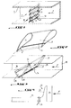
- reference numbers 1 and 2 denote respectively a flow channel of a fluid F and a first embodiment of a separator of water droplets contained in the fluid flow.
- the separator 2 comprises a plurality of fins 4 arranged in a plane perpendicular to the flow F, at a distance from each other others such as the leading edge 5 and trailing edge 6 of two adjacent fins slightly overlap in the direction of flow F.
- the fins are mounted in channel 1 so that their deflector face 8 is inclined so as to cause a deflection of the flow.
- Each fin is produced in the form of a hollow body and present, relatively close to its downstream edge or edge of leak 6, a slot 9 which passes through the wall 10, the face of which external constitutes the deflecting surface 8.
- the interior 11 of each fin is connected to a space not shown, in which there is a pressure which is lower than that prevailing in the flow channel.
- the fins are profiled.
- FIG. 3 shows a second embodiment, in which the deflecting surface of the fluid F is the face front 14 of a single inclined hollow plate 15 which extends up to a predetermined distance from the bottom wall of the canal. Offset backwards from plate 15 extends, also inclined, but in the direction opposite to plate 15, a deflector plate 16 so to establish a chicane with the latter.
- the hollow plate 15 has, near its trailing edge 6 a slot 17 which extends over the entire width of the plate and crosses the wall 19 of the circulation channel.
- the inside of the plate 15 is connected to a vacuum space and the plate is provided of a water evacuation pipe which accumulates in the plate after passing through the collector slot 17.
- the plate 16 has a slot on a deflecting surface suction 18 in its downstream part and can be provided a device 41 for recovering water at its base, that is to say at its upstream edge to allow water separated by the plate 15 but not recovered by the slot 17 to be picked up immediately by plate 16.
- This device 41 could be formed essentially by another slot.
- deflecting surfaces 8, 14 of the fins 4 or plate 14 instead of having slots manifolds can be crossed by recesses of other nature, such as for example holes distributed over the surface. Water flowing along the surface under the effect of depression, will then be sucked into inside the fin or plate, through the holes.
- the recovery device 41 in FIG. 3 could then be an area with holes or porous, as will be described in detail later.
- the deflecting surface can be covered a layer of a hydrophilic material such as earth cooked, which has a certain porosity and absorbs water. Water may even enter space internal fins or separation plate thanks to the porosity of their deflecting wall.
- Figure 4 shows schematically a use advantageous of a separator according to the invention, namely the arrangement of the separator at the outlet of a heat exchanger heat 25, in the transition zone 20 of the section significant cross-section of the exchanger towards the section comparatively small transverse flow channel 21.
- the inclined deflecting face could then be formed by the front face of the wall 23 of the transition zone.
- This wall is hollow and provided with suction recesses water that has separated from the fluid from the heat exchanger. The water that is removed from the fluid is evacuated in 24.
- Hydrophilic material can also be installed on walls of the transition zone 20 upstream of the slots manifold suction 24.
- the separator according to the invention has the advantage that it can be installed in low speed areas of flow, as shown in Figure 4. It is note that the pressure difference between the interior of the channel and the outside can be relatively small, by example of the order of 4 or 5 millibars.
- FIG. 5 shows a particularly embodiment advantageous of a separator according to the invention.
- This separator indicated generally by the number 27 is produced as a relatively thick module weak in the direction of fluid flow.
- this separator has a certain number of hollow plates 28 arranged in a row perpendicular to the flow path, parallel to each other and inclined to the axis of the channel and therefore to the direction of flow of the fluid, indicated by arrow F. These plates are juxtaposed with way that the leading leading edge 29 of a plate and the trailing edge 30 of the adjacent plate overlap somewhat to prevent fluid from passing to through the module without hitting the front deflector face 31 of a plate.
- each plate 28 is advantageously formed by a flat tube whose at minus the reflective front face 31 has a certain number of holes 32 which pass through the wall of the tube and are regularly distributed over this entire deflector face 31.
- the distribution of the holes is regular on this surface.
- the number of holes, their diameter and the geometry of their distribution are chosen according to the parameters of fluid flow and tube orientation by relation to the sense of gravity.
- the plates 28 are arranged in a frame 33 of form rectangular with upper and lower sides produced in the form of collecting chambers in which open the flat tubes constituting the hollow plates 28.
- the lower chamber indicated at 34 constitutes the water collecting chamber separated from the fluid.
- the fitting is designated by 35. It is connected to the source of depression.
- Figure 8 shows an advantageous use of the separator 27. Thanks to its small thickness it can be easily integrated into the collector 37 of a heat exchanger heat 38 receiving the two temperature fluids different in 39 and 40.
- the reflecting surface 31 containing the holes 32 can be covered with a hydrophilic product.
- the power of extraction water separator 27 can be increased considerably.
- Elements called tubes can have a cross section any and a very diverse manufacturing method using any type of material (metal, plastic, etc.) and assembly (welding, soldering, bonding, etc.)
Landscapes
- Chemical & Material Sciences (AREA)
- Chemical Kinetics & Catalysis (AREA)
- Separating Particles In Gases By Inertia (AREA)
- Separation Using Semi-Permeable Membranes (AREA)
- Physical Water Treatments (AREA)
- Heat-Exchange Devices With Radiators And Conduit Assemblies (AREA)
Abstract
Description
- la figure 1 est une vue en perspective et en coupe axiale d'un canal d'écoulement d'un fluide équipé d'un premier mode de réalisation d'un séparateur selon l'invention ;
- la figure 2 est une vue en perspective, à plus grande échelle, et avec arrachement, d'un élément déflecteur montré en II sur la figure 1 ;
- la figure 3 est une vue similaire à la figure 1, mais montrant un séparateur selon un deuxième mode de réalisation ;
- la figure 4 est une vue schématique illustrant l'utilisation d'un séparateur selon l'invention, à la sortie d'un échangeur de chaleur ;
- la figure 5 est une vue en perspective d'un mode de réalisation particulièrement avantageux d'un séparateur selon l'invention ;
- la figure 6 est une vue en coupe le long de la ligne VI-VI de la figure 5 ;
- la figure 7 est une vue en perspective d'une plaque déflectrice du séparateur selon la figure 5, et
- la figure 8 est une vue schématique de l'utilisation du séparateur selon la figure 5 dans le collecteur de sortie d'un échangeur de chaleur.
Claims (11)
- Séparateur de gouttelettes d'eau contenues dans un écoulement de fluide s'écoulant dans une voie d'écoulement, avantageusement en forme d'un canal, du type comprenant au moins une surface déflectrice inclinée montée à l'intérieur de la voie d'écoulement, de façon que les gouttes se séparent du fluide lorsque ce dernier est dévié par ladite surface déflectrice, la surface déflectrice (8, 14) comportant des évidements collecteurs (9, 17) de l'eau séparée, caractérisé en ce que les évidements sont reliés à un espace dans lequel règne une dépression par rapport à la pression dans le canal d'écoulement (1).
- Séparateur selon la revendication 1, caractérisé en ce que la surface déflectrice est formée par la surface (14) d'au moins une plaque creuse (15) dont la paroi déflectrice est pourvue des évidements précités traversants et dont l'intérieur communique avec l'espace de dépression précité et un dispositif collecteur de l'eau recueillie.
- Séparateur selon la revendication 2, caractérisé en ce que la surface déflectrice est formée par les surfaces déflectrices (8) d'une pluralité de plaques creuses (4) inclinées, agencées de façon à être décalées les unes des autres perpendiculairement à l'écoulement de fluide F, avec un léger chevauchement dans la direction axiale de l'écoulement des bords de fuite (6) et d'attaque (5) de deux plaques (4) adjacentes.
- Séparateur selon la revendication 3, caractérisé en ce que les plaques déflectrices précitées (4) sont réalisées sous forme d'ailettes de section profilée pour réduire les pertes de charge de l'écoulement F.
- Séparateur selon l'une des revendications précédentes, caractérisé en ce que les évidements précités sont formés par une fente (9, 16) pratiquée le long du bord de fuite d'une surface déflectrice (8, 14).
- Séparateur selon l'une des revendications 1 à 4, caractérisé en ce que les évidements précités dans une surface déflectrice (8, 14) sont formés par des trous répartis sur cette surface.
- Séparateur selon l'une des revendications précédentes, caractérisée en ce qu'une surface déflectrice (8, 14) est recouverte d'une couche en matériau hydrophile adapté pour éviter la formation de gouttes sur cette surface.
- Séparateur selon l'une des revendications précédentes, caractérisé en ce que la surface déflectrice (8, 14) est la surface d'une paroi en matériau poreux et les évidements précités sont formés par des voies capillaires traversant cette paroi.
- Séparateur selon l'une des revendications précédentes, caractérisé en ce qu'il est disposé à la sortie d'un échangeur de chaleur (25) sur les parois de la partie de transition (20) de la sortie à grande section transversale d'écoulement vers la gaine d'écoulement de section transversale plus réduite (21), la surface déflectrice inclinée étant formée avantageusement par des parties (23) de la zone de transition (20).
- Séparateur selon l'une des revendications 3 ou 5 à 9, caractérisé en ce que les plaques creuses (28) comportent des faces réflectrices sensiblement planes (31), inclinées par rapport à l'écoulement du fluide (F) et en ce que les plaques (28) sont juxtaposées, dans un même plan perpendiculaire à l'axe de la voie d'écoulement.
- Séparateur selon la revendication 10, caractérisé en ce que les plaques (28) sont formées par des tubes plats.
Applications Claiming Priority (2)
| Application Number | Priority Date | Filing Date | Title |
|---|---|---|---|
| FR9713920A FR2770417B1 (fr) | 1997-11-05 | 1997-11-05 | Separateur de l'eau contenue dans un ecoulement de fluide |
| FR9713920 | 1997-11-05 |
Publications (2)
| Publication Number | Publication Date |
|---|---|
| EP0914855A1 true EP0914855A1 (fr) | 1999-05-12 |
| EP0914855B1 EP0914855B1 (fr) | 2004-06-09 |
Family
ID=9513069
Family Applications (1)
| Application Number | Title | Priority Date | Filing Date |
|---|---|---|---|
| EP98402739A Expired - Lifetime EP0914855B1 (fr) | 1997-11-05 | 1998-11-03 | Séparateur de l'eau contenue dans un écoulement de fluide |
Country Status (8)
| Country | Link |
|---|---|
| US (1) | US6171379B1 (fr) |
| EP (1) | EP0914855B1 (fr) |
| JP (1) | JP4445052B2 (fr) |
| AT (1) | ATE268630T1 (fr) |
| DE (1) | DE69824367D1 (fr) |
| FR (1) | FR2770417B1 (fr) |
| IL (1) | IL126894A (fr) |
| SG (1) | SG70133A1 (fr) |
Cited By (3)
| Publication number | Priority date | Publication date | Assignee | Title |
|---|---|---|---|---|
| WO2006138114A3 (fr) * | 2005-06-17 | 2007-04-19 | Eastman Chem Co | Separateurs gaz/liquide a impact |
| WO2010031550A1 (fr) * | 2008-09-17 | 2010-03-25 | Berbel Ablufttechnik Gmbh | Hotte aspirante |
| FR2996463A1 (fr) * | 2012-10-10 | 2014-04-11 | Inst Nat De Recherche En Sciences Et Technologies Pour L'environnement Et L'agriculture Irstea | Ensemble de piegeage de particules en suspension dans un fluide |
Families Citing this family (6)
| Publication number | Priority date | Publication date | Assignee | Title |
|---|---|---|---|---|
| US7601193B2 (en) * | 2006-05-19 | 2009-10-13 | Eastman Chemical Company | Gas-liquid separator utilizing turning vanes to capture liquid droplets as well as redirect the gas flow around a bend |
| DE102007011664B4 (de) * | 2007-03-09 | 2016-08-18 | Berbel Ablufttechnik Gmbh | Filtervorrichtung zur Abscheidung von Schmutzpartikeln |
| US20090205493A1 (en) * | 2008-02-20 | 2009-08-20 | Thompson Loren M | Method of removing water from an inlet region of an oxygen generating system |
| DE202008016962U1 (de) | 2008-12-20 | 2010-05-27 | Rehau Ag + Co | Tropfenabscheideranordnung |
| EP3157651B1 (fr) * | 2014-06-18 | 2021-01-27 | Alupro OY | Séparateur à lamelles |
| US10819944B2 (en) * | 2016-12-16 | 2020-10-27 | Seagate Technology Llc | Mobile wireless drive storage for mobile phone used as car dashboard camera |
Citations (8)
| Publication number | Priority date | Publication date | Assignee | Title |
|---|---|---|---|---|
| US2083764A (en) * | 1935-11-13 | 1937-06-15 | Master Separator And Valve Com | Scrubber |
| GB1092348A (en) * | 1965-11-10 | 1967-11-22 | Parsons C A & Co Ltd | Improvements in and relating to steam turbine plants |
| DE2823942B1 (de) * | 1978-06-01 | 1979-10-11 | Alsthom Atlantique | Fluessigkeitsabscheider |
| JPS56163750A (en) * | 1980-05-22 | 1981-12-16 | Sankyo Dengiyou Kk | Liquid drop separator |
| SU1174062A1 (ru) * | 1983-09-16 | 1985-08-23 | Всесоюзный Научно-Исследовательский И Проектный Институт По Подготовке К@ Транспортировке И Переработке Природного Газа | Центробежный сепаратор |
| GB2189161A (en) * | 1986-04-17 | 1987-10-21 | Secr Defence | Separators |
| EP0272765A1 (fr) * | 1986-12-23 | 1988-06-29 | Burgess-Manning Limited | Séparateur du type à plaques |
| EP0462687A1 (fr) * | 1990-06-20 | 1991-12-27 | Peerless Manufacturing Company | Aile-séparatrice à haute capacité |
Family Cites Families (4)
| Publication number | Priority date | Publication date | Assignee | Title |
|---|---|---|---|---|
| US3254475A (en) * | 1963-07-30 | 1966-06-07 | Farr Co | Mist collector |
| US3868830A (en) * | 1973-08-31 | 1975-03-04 | Nasa | Condensate removal device for heat exchanger |
| EP0096916B1 (fr) * | 1982-06-14 | 1985-09-18 | BBC Aktiengesellschaft Brown, Boveri & Cie. | Séparateur d'eau à haute vitesse |
| GB8630750D0 (en) * | 1986-12-23 | 1987-02-04 | Burgess Manning Ltd | Vane-type separator |
-
1997
- 1997-11-05 FR FR9713920A patent/FR2770417B1/fr not_active Expired - Lifetime
-
1998
- 1998-11-03 DE DE69824367T patent/DE69824367D1/de not_active Expired - Lifetime
- 1998-11-03 EP EP98402739A patent/EP0914855B1/fr not_active Expired - Lifetime
- 1998-11-03 AT AT98402739T patent/ATE268630T1/de not_active IP Right Cessation
- 1998-11-04 US US09/185,678 patent/US6171379B1/en not_active Expired - Fee Related
- 1998-11-04 IL IL12689498A patent/IL126894A/en active IP Right Grant
- 1998-11-05 SG SG1998004551A patent/SG70133A1/en unknown
- 1998-11-05 JP JP31456798A patent/JP4445052B2/ja not_active Expired - Fee Related
Patent Citations (8)
| Publication number | Priority date | Publication date | Assignee | Title |
|---|---|---|---|---|
| US2083764A (en) * | 1935-11-13 | 1937-06-15 | Master Separator And Valve Com | Scrubber |
| GB1092348A (en) * | 1965-11-10 | 1967-11-22 | Parsons C A & Co Ltd | Improvements in and relating to steam turbine plants |
| DE2823942B1 (de) * | 1978-06-01 | 1979-10-11 | Alsthom Atlantique | Fluessigkeitsabscheider |
| JPS56163750A (en) * | 1980-05-22 | 1981-12-16 | Sankyo Dengiyou Kk | Liquid drop separator |
| SU1174062A1 (ru) * | 1983-09-16 | 1985-08-23 | Всесоюзный Научно-Исследовательский И Проектный Институт По Подготовке К@ Транспортировке И Переработке Природного Газа | Центробежный сепаратор |
| GB2189161A (en) * | 1986-04-17 | 1987-10-21 | Secr Defence | Separators |
| EP0272765A1 (fr) * | 1986-12-23 | 1988-06-29 | Burgess-Manning Limited | Séparateur du type à plaques |
| EP0462687A1 (fr) * | 1990-06-20 | 1991-12-27 | Peerless Manufacturing Company | Aile-séparatrice à haute capacité |
Non-Patent Citations (1)
| Title |
|---|
| PATENT ABSTRACTS OF JAPAN vol. 006, no. 049 (C - 096) 31 March 1982 (1982-03-31) * |
Cited By (6)
| Publication number | Priority date | Publication date | Assignee | Title |
|---|---|---|---|---|
| WO2006138114A3 (fr) * | 2005-06-17 | 2007-04-19 | Eastman Chem Co | Separateurs gaz/liquide a impact |
| US7537627B2 (en) | 2005-06-17 | 2009-05-26 | Eastman Chemical Company | Gas-liquid impingement separators |
| WO2010031550A1 (fr) * | 2008-09-17 | 2010-03-25 | Berbel Ablufttechnik Gmbh | Hotte aspirante |
| FR2996463A1 (fr) * | 2012-10-10 | 2014-04-11 | Inst Nat De Recherche En Sciences Et Technologies Pour L'environnement Et L'agriculture Irstea | Ensemble de piegeage de particules en suspension dans un fluide |
| WO2014057225A1 (fr) | 2012-10-10 | 2014-04-17 | Institut National De Recherche En Sciences Et Technologies Pour L'environnement Et L'agriculture (Irstea) | Ensemble de piegeage de particules en suspension dans un fluide |
| CN104797319A (zh) * | 2012-10-10 | 2015-07-22 | 法国农业与环境科技研究所 | 捕获悬浮在流体中的颗粒的组件 |
Also Published As
| Publication number | Publication date |
|---|---|
| SG70133A1 (en) | 2000-01-25 |
| JPH11197425A (ja) | 1999-07-27 |
| US6171379B1 (en) | 2001-01-09 |
| FR2770417B1 (fr) | 2001-01-26 |
| JP4445052B2 (ja) | 2010-04-07 |
| IL126894A0 (en) | 1999-09-22 |
| DE69824367D1 (de) | 2004-07-15 |
| EP0914855B1 (fr) | 2004-06-09 |
| FR2770417A1 (fr) | 1999-05-07 |
| ATE268630T1 (de) | 2004-06-15 |
| IL126894A (en) | 2002-02-10 |
Similar Documents
| Publication | Publication Date | Title |
|---|---|---|
| EP2406463B1 (fr) | Aube de turbine avec un trou de depoussiérage en base de pale. | |
| EP0879357B1 (fr) | Micropompe comprenant un filtre micro-usine | |
| FR2869100A1 (fr) | Dissipateur thermique a fluide pulse | |
| EP0914855B1 (fr) | Séparateur de l'eau contenue dans un écoulement de fluide | |
| EP3175181A1 (fr) | Echangeur enthalpique ameliore | |
| EP2912396B1 (fr) | Échangeur thermique, notamment pour vehicule automobile | |
| FR2799502A1 (fr) | Deflecteur d'huile | |
| WO2019063946A1 (fr) | Dispositif de ventilation pour module d'echange de chaleur de vehicule automobile a guides d'air du flux d'air traversant les collecteurs d'air | |
| EP1533585B1 (fr) | Echangeur de chaleur à empilement de plaques | |
| EP3857156B1 (fr) | Plaque d'échangeur de chaleur a ouverture optimisée | |
| FR2929858A1 (fr) | Filtre a carburant et cartouche filtrante permettant un degazage | |
| FR3128901A1 (fr) | Module de refroidissement pour vehicule automobile avec un systeme de drainage | |
| FR2837917A1 (fr) | Echangeur de chaleur, notamment pour un vehicule automobile, constitue d'elements tubulaires empiles | |
| EP1170565A1 (fr) | Echangeur de chaleur du type à deux voies d'écoulement de fluide | |
| EP4562353A1 (fr) | Dispositif amélioré de climatisation par refroidissement indirect par évaporation | |
| EP4121708B1 (fr) | Echangeur thermique pour véhicule automobile | |
| FR3067098B1 (fr) | Dispositif de ventilation destine a generer un flux d'air a travers un echangeur de chaleur de vehicule automobile | |
| EP3482148B1 (fr) | Échangeur thermique et véhicule comprenant cet échangeur | |
| EP0836057B1 (fr) | Bac de collecte des condensats et appareil frigorifique équipé d'un tel bac | |
| EP1558887A2 (fr) | Echangeur de chaleur a passes multiples, en particulier pour vehicule automobile | |
| WO2024251686A1 (fr) | Elément interne d'échangeur de chaleur | |
| EP4078056A1 (fr) | Echangeur de chaleur avec collecteur rapporté | |
| FR2538525A1 (fr) | Moyen permettant un transfert de chaleur eleve pour echangeur de chaleur a tubes et ailettes plats | |
| FR3135518A1 (fr) | Dispositif de régulation thermique pour refroidissement d’organe de stockage d’énergie électrique | |
| FR3075262B1 (fr) | Systeme de ventilation pour module d'echange de chaleur de vehicule automobile comprenant un dispositif de ventilation a tubes |
Legal Events
| Date | Code | Title | Description |
|---|---|---|---|
| PUAI | Public reference made under article 153(3) epc to a published international application that has entered the european phase |
Free format text: ORIGINAL CODE: 0009012 |
|
| AK | Designated contracting states |
Kind code of ref document: A1 Designated state(s): AT BE CH CY DE LI |
|
| AX | Request for extension of the european patent |
Free format text: AL;LT;LV;MK;RO;SI |
|
| 17P | Request for examination filed |
Effective date: 19991014 |
|
| AKX | Designation fees paid |
Free format text: AT BE CH CY DE LI |
|
| RBV | Designated contracting states (corrected) |
Designated state(s): AT DE GB IT NL |
|
| 17Q | First examination report despatched |
Effective date: 20021120 |
|
| GRAP | Despatch of communication of intention to grant a patent |
Free format text: ORIGINAL CODE: EPIDOSNIGR1 |
|
| GRAS | Grant fee paid |
Free format text: ORIGINAL CODE: EPIDOSNIGR3 |
|
| GRAA | (expected) grant |
Free format text: ORIGINAL CODE: 0009210 |
|
| AK | Designated contracting states |
Kind code of ref document: B1 Designated state(s): AT DE GB IT NL |
|
| PG25 | Lapsed in a contracting state [announced via postgrant information from national office to epo] |
Ref country code: NL Free format text: LAPSE BECAUSE OF FAILURE TO SUBMIT A TRANSLATION OF THE DESCRIPTION OR TO PAY THE FEE WITHIN THE PRESCRIBED TIME-LIMIT Effective date: 20040609 Ref country code: IT Free format text: LAPSE BECAUSE OF FAILURE TO SUBMIT A TRANSLATION OF THE DESCRIPTION OR TO PAY THE FEE WITHIN THE PRE;WARNING: LAPSES OF ITALIAN PATENTS WITH EFFECTIVE DATE BEFORE 2007 MAY HAVE OCCURRED AT ANY TIME BEFORE 2007. THE CORRECT EFFECTIVE DATE MAY BE DIFFERENT FROM THE ONE RECORDED.SCRIBED TIME-LIMIT Effective date: 20040609 Ref country code: GB Free format text: LAPSE BECAUSE OF FAILURE TO SUBMIT A TRANSLATION OF THE DESCRIPTION OR TO PAY THE FEE WITHIN THE PRESCRIBED TIME-LIMIT Effective date: 20040609 Ref country code: AT Free format text: LAPSE BECAUSE OF FAILURE TO SUBMIT A TRANSLATION OF THE DESCRIPTION OR TO PAY THE FEE WITHIN THE PRESCRIBED TIME-LIMIT Effective date: 20040609 |
|
| REG | Reference to a national code |
Ref country code: GB Ref legal event code: FG4D Free format text: NOT ENGLISH |
|
| REF | Corresponds to: |
Ref document number: 69824367 Country of ref document: DE Date of ref document: 20040715 Kind code of ref document: P |
|
| PG25 | Lapsed in a contracting state [announced via postgrant information from national office to epo] |
Ref country code: DE Free format text: LAPSE BECAUSE OF FAILURE TO SUBMIT A TRANSLATION OF THE DESCRIPTION OR TO PAY THE FEE WITHIN THE PRESCRIBED TIME-LIMIT Effective date: 20040910 |
|
| NLV1 | Nl: lapsed or annulled due to failure to fulfill the requirements of art. 29p and 29m of the patents act | ||
| GBV | Gb: ep patent (uk) treated as always having been void in accordance with gb section 77(7)/1977 [no translation filed] |
Effective date: 20040609 |
|
| PLBE | No opposition filed within time limit |
Free format text: ORIGINAL CODE: 0009261 |
|
| STAA | Information on the status of an ep patent application or granted ep patent |
Free format text: STATUS: NO OPPOSITION FILED WITHIN TIME LIMIT |
|
| 26N | No opposition filed |
Effective date: 20050310 |