EP0914760B1 - Arrangement for weeding between planted row crops - Google Patents
Arrangement for weeding between planted row crops Download PDFInfo
- Publication number
- EP0914760B1 EP0914760B1 EP98203628A EP98203628A EP0914760B1 EP 0914760 B1 EP0914760 B1 EP 0914760B1 EP 98203628 A EP98203628 A EP 98203628A EP 98203628 A EP98203628 A EP 98203628A EP 0914760 B1 EP0914760 B1 EP 0914760B1
- Authority
- EP
- European Patent Office
- Prior art keywords
- rod
- arrangement
- plant
- row
- weeding
- Prior art date
- Legal status (The legal status is an assumption and is not a legal conclusion. Google has not performed a legal analysis and makes no representation as to the accuracy of the status listed.)
- Expired - Lifetime
Links
Images


Classifications
-
- A—HUMAN NECESSITIES
- A01—AGRICULTURE; FORESTRY; ANIMAL HUSBANDRY; HUNTING; TRAPPING; FISHING
- A01B—SOIL WORKING IN AGRICULTURE OR FORESTRY; PARTS, DETAILS, OR ACCESSORIES OF AGRICULTURAL MACHINES OR IMPLEMENTS, IN GENERAL
- A01B69/00—Steering of agricultural machines or implements; Guiding agricultural machines or implements on a desired track
- A01B69/003—Steering or guiding of machines or implements pushed or pulled by or mounted on agricultural vehicles such as tractors, e.g. by lateral shifting of the towing connection
- A01B69/004—Steering or guiding of machines or implements pushed or pulled by or mounted on agricultural vehicles such as tractors, e.g. by lateral shifting of the towing connection automatic
-
- A—HUMAN NECESSITIES
- A01—AGRICULTURE; FORESTRY; ANIMAL HUSBANDRY; HUNTING; TRAPPING; FISHING
- A01B—SOIL WORKING IN AGRICULTURE OR FORESTRY; PARTS, DETAILS, OR ACCESSORIES OF AGRICULTURAL MACHINES OR IMPLEMENTS, IN GENERAL
- A01B39/00—Other machines specially adapted for working soil on which crops are growing
- A01B39/12—Other machines specially adapted for working soil on which crops are growing for special purposes, e.g. for special culture
- A01B39/18—Other machines specially adapted for working soil on which crops are growing for special purposes, e.g. for special culture for weeding
Definitions
- the invention relates to an arrangement for weeding between planted or seeded row crops, provided with weed cutting blades which are in operational conditions pulled in an at least substantially horizontal position under ground level along a plant row, which blades are each individually connected via a blade stem to an arm, which arms are hingedly connected to a frame and provided with guiding means, for limiting the movements of the weed cutting blades in a direction towards the plant row.
- the present invention is intended for weeding between planted or seeded row crops with short distances between individual plants. In this case it would be practically impossible to weed round individual plants.
- the inventive weeding arrangement is therefore characterized in that the guiding means comprise substantially rod-shaped objects which are operationally pulled along the plant row and rest against a plurality of plants in that plant row. In this way, the blades can be pulled at a very small distance along the plant row, without the need for an expensive hydraulic servo system.
- the inventive arrangement is especially suited for weeding between rows of a crop standing on a relatively strong stem, like maize or young trees, because the crop must be capable of offering at least some resistance to the guiding means, but the force, necessary for steering the blade, is distributed over a plurality of plants, which makes the arrangement well suited for weeding between rows of a relatively young crop.
- An arrangement for ploughing between vines is also known from FR 389 550.
- a ploughshare is provided with a projection which will contact a vine when it approaches it and it will push the the ploughshare aside so as not to touch the vine.
- the guiding means guides the ploughshare round an individual vine.
- An arrangement for weeding provided with guiding means is also known from US 2 633 790, but with this arrangement the guiding means are exclusively used for lifting up the crop, such that the weed cutting blade moving alongside the guiding means will not damage the crop, while the position of the weed cutting blades is solely determined by the driving skills of the driver.
- An advantageous embodiment which can very well cope with a possible unevenness of the ground, is characterized in that connecting means of the rod-shaped objects are provided with hinge means, for enabling the rod-shaped objects to move in a vertical direction.
- a further advantageous embodiment which aims at reducing the mechanical load of the crop to a minimum is characterized in that arresting means are provided, like chains or cams, for in operational conditions maintaining a minimum distance between two rod-shaped objects positioned at opposite sides of a plant row. As the forces generated by both cutting blades substantially balance, the positions of the cutting blades will only incidentally, if necessary, be corrected by the rod-shaped objects.
- An advantageous embodiment which uses this fact is characterized in that the arrangement is provided with two groups of weed cutting blades, a first group in operational conditions being pulled along a first side of a number of plant rows and a second group in operational conditions being pulled along a second side of the plant rows, and that for each group at least one rod-shaped object is provided which is operationally pulled along a plant row and rests against a plurality of plants in that plant row.
- one may have a first group of four cutting blades, weeding the left sides of four plant rows and a second group of four cutting blades, weeding the right sides.
- Fig. 1A shows in top view a first embodiment of the weeding arrangement, comprising a frame 1, on which two arms 3a,3b are hingedly connected with the aid of two clamps 2a,2b and two bearings 4a,4b. Arms 3a,3b are on the other ends provided with vertically disposed blade stems 5a,5b, not visible in the figure, which are on their lower ends provided with two weed cutting blades 6a,6b.
- frame 1 is pulled in a known manner by a tractor, such that the arms 3a,3b are disposed substantially horizontally and weed cutting blades 6a,6b are located just below ground level.
- the aim is to lead the cutting blades 6a,6b at a short distance along a seeded or planted row of crop 7a,7b,7c,..
- pushing means are provided on one hand for pushing the arms 3a,3b together and guiding means are provided on the other hand for preventing cutting blades 6a,6b from touching the crop.
- the arms 3a,3b may be mutually connected by a spring for example, but in this embodiment the force driving the arms together is obtained by the cutting blades 6a,6b themselves, which have been shaped asymmetrically for that purpose.
- the guiding means are realized as two rod-shaped objects 8a,8b, which operationally glide along the crop and which are connected to the arms 3a,3b.
- Fig. 1B represents the first embodiment of the weeding arrangement in side view, with frame 1, clamp 2b, arm 3b bearing 4b, blade stem 5b and cutting blade 6b being visible.
- frame 1 is provided with wheels, of which one wheel 12 is visible, and is coupled to a tractor via a height adjustment, well known in the art, with which the depth of the cutting blades 6a,6b can be adjusted.
- the rod-shaped objects 8a,8b remain exactly above ground level, thanks to the cooperating horizontally disposed connecting means 9a,9b, the hinges 10a, 10b and the substantially vertically disposed connecting means 11a, 11b.
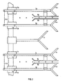
- Fig. 2 represents in top view a compound weeding arrangement, which is in this embodiment suited for simultaneously weeding two plant rows with the aid of the movably attached cutting blades 6a,6b,6c,6d and with the fixed cutting blade 13, which is intended for weeding the remaining surface between the plant rows.
- Cutting blades 6a,6b,6c,6d are connected again via the arms 3a,3b,3c,3d, hinges 4a,4b,4c,4d and clamps 2a,2b,2c,2d to a frame 1, which can be pulled forward by a tractor. Steering of the cutting blades 6a,6b,6c,6d again takes place via the rod-shaped objects 8a,8b,8c,8d.
- the rod-shaped objects 8a,8b,8c,8d are continuously pushed against the row of crop 7a,7b,7c,... It is possible to limit the inward movement in another way, for example by arresting cams between the arms 3a,3b and between 3c,3d or, like here, by arresting chains 14a,14b connected between the forward pointing extensions of the arms 3a,3b,3c,3d. With these arresting means one may for example adjust a minimum distance of five centimetres between the rod-shaped objects 8a,8b. The advantage is that it is no longer necessary for the crop to continuously deliver a counterforce, resulting in a smaller load perceived by the crop.
- Fig. 3A represents a second embodiment of the weeding arrangement in top view, in which the arms are replaced by pairs of arms 15a,15b and 15c,15d, mounted in parallel.
- Arms 15a,15b are on one end hingedly connected to clamp 2a by bearings 16a,16b and on the other end provided with a blade holder 17a under application of hinges 18a,18b.
- Arms 15c,15d are in the same way on one end connected to clamp 2b with the aid of bearings 19a,19b and on the other end provided with a blade holder 17b under application of bearings 20a,20b.
- This construction which is known as a parallel guiding, has the effect that the arms 15a,15b and the arms 15c,15d can swing, but that the blade holders 17a,17b and the cutting blades 6a,6b move in parallel and thus remain in the same position.
- the rod-shaped objects 8a,8b may now be connected to the blade holders 17a,17b via the horizontal connecting means 9a,9b, hinges 10a,10b and the vertical connecting means 11a,11b.
- the result is that the weeding arrangement precisely follows the row of crop 7a,7b,7c,.. and that the rod-shaped objects 8a,8b remain parallel to the plant row.
- Fig. 3B represents the second embodiment of the weeding arrangement in side view. Visible are the arm 15b, horizontal connecting means 9b, hinge 10b and vertical connecting means 11b, which form a connection to the blade holder 17b.
Landscapes
- Life Sciences & Earth Sciences (AREA)
- Engineering & Computer Science (AREA)
- Mechanical Engineering (AREA)
- Soil Sciences (AREA)
- Environmental Sciences (AREA)
- Soil Working Implements (AREA)
- Harvester Elements (AREA)
Abstract
Description
- The invention relates to an arrangement for weeding between planted or seeded row crops, provided with weed cutting blades which are in operational conditions pulled in an at least substantially horizontal position under ground level along a plant row, which blades are each individually connected via a blade stem to an arm, which arms are hingedly connected to a frame and provided with guiding means, for limiting the movements of the weed cutting blades in a direction towards the plant row.
- An arrangement of this kind is known from DE 36 18 064 A. The known arrangement is intended for ploughing between vines and the guiding means are designed for precisely guiding a blade round an individual vine. For that purpose, use is made of a sensor sensing individual vines, coupled to a hydraulic servo system, coupled to the arm onto which the blade is connected.
- The present invention is intended for weeding between planted or seeded row crops with short distances between individual plants. In this case it would be practically impossible to weed round individual plants. The inventive weeding arrangement is therefore characterized in that the guiding means comprise substantially rod-shaped objects which are operationally pulled along the plant row and rest against a plurality of plants in that plant row. In this way, the blades can be pulled at a very small distance along the plant row, without the need for an expensive hydraulic servo system.
- The inventive arrangement is especially suited for weeding between rows of a crop standing on a relatively strong stem, like maize or young trees, because the crop must be capable of offering at least some resistance to the guiding means, but the force, necessary for steering the blade, is distributed over a plurality of plants, which makes the arrangement well suited for weeding between rows of a relatively young crop.
- An arrangement for ploughing between vines is also known from FR 389 550. In the known arrangement, a ploughshare is provided with a projection which will contact a vine when it approaches it and it will push the the ploughshare aside so as not to touch the vine. In this way, the guiding means guides the ploughshare round an individual vine.
- An arrangement for weeding provided with guiding means is also known from US 2 633 790, but with this arrangement the guiding means are exclusively used for lifting up the crop, such that the weed cutting blade moving alongside the guiding means will not damage the crop, while the position of the weed cutting blades is solely determined by the driving skills of the driver.
- An advantageous embodiment which can very well cope with a possible unevenness of the ground, is characterized in that connecting means of the rod-shaped objects are provided with hinge means, for enabling the rod-shaped objects to move in a vertical direction.
- A further advantageous embodiment which aims at reducing the mechanical load of the crop to a minimum, is characterized in that arresting means are provided, like chains or cams, for in operational conditions maintaining a minimum distance between two rod-shaped objects positioned at opposite sides of a plant row. As the forces generated by both cutting blades substantially balance, the positions of the cutting blades will only incidentally, if necessary, be corrected by the rod-shaped objects.
- With a mechanically planted or seeded crop the distance between the plant rows in a group or between a group of rows often is exactly the same. An advantageous embodiment which uses this fact is characterized in that the arrangement is provided with two groups of weed cutting blades, a first group in operational conditions being pulled along a first side of a number of plant rows and a second group in operational conditions being pulled along a second side of the plant rows, and that for each group at least one rod-shaped object is provided which is operationally pulled along a plant row and rests against a plurality of plants in that plant row. As an example one may have a first group of four cutting blades, weeding the left sides of four plant rows and a second group of four cutting blades, weeding the right sides.
- The invention will now be further explained with reference to the following figures, in which:
- Fig. 1A
- represents a first embodiment of the weeding arrangement in top view;
- Fig. 1B
- represents the first embodiment of the weeding arrangement in side view;
- Fig. 2
- represents in top view a compound weeding arrangement;
- Fig. 3A
- represents a second embodiment of the weeding arrangement in top view;
- Fig. 3B
- represents the second embodiment of the weeding arrangement in side view.
- Fig. 1A shows in top view a first embodiment of the weeding arrangement, comprising a frame 1, on which two
arms clamps bearings 4a,4b.Arms blade stems weed cutting blades arms cutting blades cutting blades crop arms cutting blades arms cutting blades shaped objects arms shaped objects shaped objects arms means hinges means 11a,11b, which are not visible in this figure. Rod-shaped objects shaped objects shaped objects - Fig. 1B represents the first embodiment of the weeding arrangement in side view, with frame 1,
clamp 2b,arm 3b bearing 4b,blade stem 5b andcutting blade 6b being visible. In operation, frame 1 is provided with wheels, of which onewheel 12 is visible, and is coupled to a tractor via a height adjustment, well known in the art, with which the depth of thecutting blades shaped objects means hinges means 11a, 11b. - Before a new plant row is weeded the
arms crop shaped objects - Fig. 2 represents in top view a compound weeding arrangement, which is in this embodiment suited for simultaneously weeding two plant rows with the aid of the movably attached
cutting blades cutting blade 13, which is intended for weeding the remaining surface between the plant rows.Cutting blades arms hinges clamps cutting blades shaped objects - Due to the shape of the
cutting blades shaped objects crop arms arms shaped objects - It will be clear that different combinations may be realized, dependent upon the type of soil and the type of crop. One may for example omit the
cutting blades shaped objects arms 3a en 3c and thearms 3b en 3d. Steering for the four cutting blades then takes place exclusively by the rod-shapedobjects objects - Fig. 3A represents a second embodiment of the weeding arrangement in top view, in which the arms are replaced by pairs of
arms Arms bearings 16a,16b and on the other end provided with a blade holder 17a under application ofhinges Arms bearings blade holder 17b under application ofbearings 20a,20b. This construction, which is known as a parallel guiding, has the effect that thearms arms blade holders 17a,17b and thecutting blades objects blade holders 17a,17b via the horizontal connectingmeans means 11a,11b. The result is that the weeding arrangement precisely follows the row ofcrop objects - Fig. 3B represents the second embodiment of the weeding arrangement in side view. Visible are the
arm 15b, horizontal connectingmeans 9b, hinge 10b and vertical connectingmeans 11b, which form a connection to theblade holder 17b.
Claims (4)
- Arrangement for weeding between planted or seeded row crops, provided with weed cutting blades (6) which are in operational conditions pulled in an at least substantially horizontal position under ground level along a plant row (7), which blades (6) are each individually connected via a blade stem (5) to an arm (3,15), which arms (3,15) are hingedly connected to a frame (1) and provided with guiding means (8), for limiting the movements of the weed cutting blades (6) in a direction towards the plant row (7), characterized in that the guiding means (8) comprise substantially rod-shaped objects which are operationally pulled along the plant row (7) and rest against a plurality of plants in that plant row (7).
- Arrangement according to claim 1, characterized in that connecting means (9) of the rod-shaped objects (8) are provided with hinge means (10), for enabling the rod-shaped objects to move in a vertical direction.
- Arrangement according to claim 1 or 2, characterized in that arresting means (14) are provided, like chains or cams, for in operational conditions maintaining a minimum distance between two rod-shaped objects (8) positioned at opposite sides of a plant row (7).
- Arrangement according to one of the previous claims, characterized in that the arrangement is provided with two groups of weed cutting blades (6), a first group in operational conditions being pulled along a first side of a number of plant rows (7) and a second group in operational conditions being pulled along a second side of the plant rows (7), and that for each group at least one rod-shaped object (8) is provided which is operationally pulled along a plant row (7) and rests against a plurality of plants in that plant row.
Applications Claiming Priority (4)
| Application Number | Priority Date | Filing Date | Title |
|---|---|---|---|
| NL1007106A NL1007106C2 (en) | 1997-09-24 | 1997-09-24 | Weeding harrow for row planted crops with adjustment for width |
| NL1007106 | 1997-09-24 | ||
| NL1010070 | 1998-09-11 | ||
| NL1010070A NL1010070C1 (en) | 1997-09-24 | 1998-09-11 | Device for hoeing between a crop planted in rows. |
Publications (3)
| Publication Number | Publication Date |
|---|---|
| EP0914760A2 EP0914760A2 (en) | 1999-05-12 |
| EP0914760A3 EP0914760A3 (en) | 2000-03-08 |
| EP0914760B1 true EP0914760B1 (en) | 2003-06-18 |
Family
ID=26642661
Family Applications (1)
| Application Number | Title | Priority Date | Filing Date |
|---|---|---|---|
| EP98203628A Expired - Lifetime EP0914760B1 (en) | 1997-09-24 | 1998-09-21 | Arrangement for weeding between planted row crops |
Country Status (4)
| Country | Link |
|---|---|
| EP (1) | EP0914760B1 (en) |
| AT (1) | ATE242955T1 (en) |
| DE (1) | DE69815629T2 (en) |
| NL (1) | NL1010070C1 (en) |
Families Citing this family (4)
| Publication number | Priority date | Publication date | Assignee | Title |
|---|---|---|---|---|
| JP4515531B1 (en) * | 2009-08-31 | 2010-08-04 | 有限会社渥美不動産アンドコーポレーション | Grass pulling device |
| NL1037338C2 (en) * | 2009-09-29 | 2011-03-30 | Gerrit Jan Dijk | HOUSING MACHINE. |
| CN103283331B (en) * | 2013-06-20 | 2016-02-10 | 苏州博田自动化技术有限公司 | The traversing facility of a kind of intelligent steering |
| AT521601B1 (en) | 2018-11-19 | 2020-03-15 | Rohringer Werner | Device for removing and chopping, in particular mulching weeds, undersowing or the like. |
Family Cites Families (7)
| Publication number | Priority date | Publication date | Assignee | Title |
|---|---|---|---|---|
| FR389550A (en) * | 1908-03-14 | 1908-09-11 | Paul Comment | Mobile share hoe |
| DE216962C (en) * | 1908-07-14 | 1909-12-13 | ||
| FR19429E (en) * | 1911-04-19 | 1915-01-29 | Maurice Massignon | Plow |
| FR26314E (en) * | 1914-04-09 | 1923-11-06 | Row crop cultivator | |
| US1831686A (en) | 1928-06-27 | 1931-11-10 | Adolph L Ritter | Cultivator and weeder |
| US2633790A (en) * | 1949-08-08 | 1953-04-07 | Jeroe P Bauer | Rotary flanged disk weed cutter |
| DE3618064A1 (en) * | 1986-05-28 | 1987-12-03 | Artur Pieroth | Plough |
-
1998
- 1998-09-11 NL NL1010070A patent/NL1010070C1/en active
- 1998-09-21 AT AT98203628T patent/ATE242955T1/en not_active IP Right Cessation
- 1998-09-21 DE DE69815629T patent/DE69815629T2/en not_active Expired - Fee Related
- 1998-09-21 EP EP98203628A patent/EP0914760B1/en not_active Expired - Lifetime
Also Published As
| Publication number | Publication date |
|---|---|
| DE69815629T2 (en) | 2004-05-13 |
| ATE242955T1 (en) | 2003-07-15 |
| NL1010070C1 (en) | 1999-03-25 |
| EP0914760A2 (en) | 1999-05-12 |
| DE69815629D1 (en) | 2003-07-24 |
| EP0914760A3 (en) | 2000-03-08 |
Similar Documents
| Publication | Publication Date | Title |
|---|---|---|
| US5279068A (en) | Crop row deviation sensing device | |
| US5394945A (en) | Precision weeding machine for row crops | |
| CA1284053C (en) | Row crop tillage and planting unit guidance system | |
| EP0914760B1 (en) | Arrangement for weeding between planted row crops | |
| AU751107B2 (en) | Row finder for a harvesting unit | |
| US20200288637A1 (en) | Harvesting inter-seeded crops | |
| RU2559949C2 (en) | Section of row processing having displacement device and seed drill with similar sections | |
| US3223177A (en) | Sway limiting means for a tool mounted on a mast type hitch | |
| US3554297A (en) | Cultivator | |
| WO2000056136A1 (en) | Apparatus for weeding between planted row crops | |
| US3247911A (en) | Rotating cultivator shield | |
| JP2880201B2 (en) | Riding type tillage transplantation method and apparatus | |
| US4333533A (en) | Weeder for row crops | |
| CN218302108U (en) | Agricultural intertillage robot | |
| CN115299195B (en) | Conical nail brush type omnibearing intelligent weeding machine | |
| CZ231693A3 (en) | Cultivator | |
| SU1701128A1 (en) | Cultivator | |
| US2633791A (en) | Plant shield for cultivators | |
| DE1176411B (en) | Tillage equipment | |
| RU2054228C1 (en) | Method and device for cultivator control during inter-row cultivation of row crops | |
| US840898A (en) | Cultivator. | |
| CA3151513A1 (en) | Ground following harrow | |
| SU1777676A1 (en) | Working tool for row crop cultivator | |
| SU1565365A1 (en) | Cultivator | |
| EP3294049A1 (en) | An agricultural implement for use in a field comprising pre-prepared tracks |
Legal Events
| Date | Code | Title | Description |
|---|---|---|---|
| PUAI | Public reference made under article 153(3) epc to a published international application that has entered the european phase |
Free format text: ORIGINAL CODE: 0009012 |
|
| AK | Designated contracting states |
Kind code of ref document: A2 Designated state(s): AT BE DE DK FR GB NL |
|
| AX | Request for extension of the european patent |
Free format text: AL;LT;LV;MK;RO;SI |
|
| PUAL | Search report despatched |
Free format text: ORIGINAL CODE: 0009013 |
|
| AK | Designated contracting states |
Kind code of ref document: A3 Designated state(s): AT BE CH CY DE DK ES FI FR GB GR IE IT LI LU MC NL PT SE |
|
| AX | Request for extension of the european patent |
Free format text: AL;LT;LV;MK;RO;SI |
|
| RIC1 | Information provided on ipc code assigned before grant |
Free format text: 7A 01B 39/18 A, 7A 01B 39/16 B |
|
| RAP1 | Party data changed (applicant data changed or rights of an application transferred) |
Owner name: DIJK, GERRIT JAN |
|
| RIN1 | Information on inventor provided before grant (corrected) |
Inventor name: DIJK, GERRIT JAN |
|
| 17P | Request for examination filed |
Effective date: 20000804 |
|
| AKX | Designation fees paid |
Free format text: AT BE CY DE DK FR GB |
|
| RBV | Designated contracting states (corrected) |
Designated state(s): AT BE DE DK FR GB NL |
|
| 17Q | First examination report despatched |
Effective date: 20010823 |
|
| RAP1 | Party data changed (applicant data changed or rights of an application transferred) |
Owner name: DIJK, GERRIT JAN |
|
| RIN1 | Information on inventor provided before grant (corrected) |
Inventor name: DIJK, GERRIT JAN |
|
| GRAG | Despatch of communication of intention to grant |
Free format text: ORIGINAL CODE: EPIDOS AGRA |
|
| RBV | Designated contracting states (corrected) |
Designated state(s): AT BE DE DK FR GB NL |
|
| GRAG | Despatch of communication of intention to grant |
Free format text: ORIGINAL CODE: EPIDOS AGRA |
|
| GRAH | Despatch of communication of intention to grant a patent |
Free format text: ORIGINAL CODE: EPIDOS IGRA |
|
| GRAH | Despatch of communication of intention to grant a patent |
Free format text: ORIGINAL CODE: EPIDOS IGRA |
|
| GRAA | (expected) grant |
Free format text: ORIGINAL CODE: 0009210 |
|
| AK | Designated contracting states |
Designated state(s): AT BE DE DK FR GB NL |
|
| PG25 | Lapsed in a contracting state [announced via postgrant information from national office to epo] |
Ref country code: BE Free format text: LAPSE BECAUSE OF FAILURE TO SUBMIT A TRANSLATION OF THE DESCRIPTION OR TO PAY THE FEE WITHIN THE PRESCRIBED TIME-LIMIT Effective date: 20030618 Ref country code: AT Free format text: LAPSE BECAUSE OF FAILURE TO SUBMIT A TRANSLATION OF THE DESCRIPTION OR TO PAY THE FEE WITHIN THE PRESCRIBED TIME-LIMIT Effective date: 20030618 |
|
| REG | Reference to a national code |
Ref country code: GB Ref legal event code: FG4D |
|
| REF | Corresponds to: |
Ref document number: 69815629 Country of ref document: DE Date of ref document: 20030724 Kind code of ref document: P |
|
| PG25 | Lapsed in a contracting state [announced via postgrant information from national office to epo] |
Ref country code: DK Free format text: LAPSE BECAUSE OF FAILURE TO SUBMIT A TRANSLATION OF THE DESCRIPTION OR TO PAY THE FEE WITHIN THE PRESCRIBED TIME-LIMIT Effective date: 20030918 |
|
| PLBE | No opposition filed within time limit |
Free format text: ORIGINAL CODE: 0009261 |
|
| STAA | Information on the status of an ep patent application or granted ep patent |
Free format text: STATUS: NO OPPOSITION FILED WITHIN TIME LIMIT |
|
| ET | Fr: translation filed | ||
| 26N | No opposition filed |
Effective date: 20040319 |
|
| PGFP | Annual fee paid to national office [announced via postgrant information from national office to epo] |
Ref country code: GB Payment date: 20040818 Year of fee payment: 7 |
|
| PGFP | Annual fee paid to national office [announced via postgrant information from national office to epo] |
Ref country code: FR Payment date: 20040830 Year of fee payment: 7 |
|
| PG25 | Lapsed in a contracting state [announced via postgrant information from national office to epo] |
Ref country code: GB Free format text: LAPSE BECAUSE OF NON-PAYMENT OF DUE FEES Effective date: 20050921 |
|
| GBPC | Gb: european patent ceased through non-payment of renewal fee |
Effective date: 20050921 |
|
| PG25 | Lapsed in a contracting state [announced via postgrant information from national office to epo] |
Ref country code: FR Free format text: LAPSE BECAUSE OF NON-PAYMENT OF DUE FEES Effective date: 20060531 |
|
| REG | Reference to a national code |
Ref country code: FR Ref legal event code: ST Effective date: 20060531 |
|
| PGFP | Annual fee paid to national office [announced via postgrant information from national office to epo] |
Ref country code: DE Payment date: 20060930 Year of fee payment: 9 |
|
| PGFP | Annual fee paid to national office [announced via postgrant information from national office to epo] |
Ref country code: NL Payment date: 20070822 Year of fee payment: 10 |
|
| PG25 | Lapsed in a contracting state [announced via postgrant information from national office to epo] |
Ref country code: DE Free format text: LAPSE BECAUSE OF NON-PAYMENT OF DUE FEES Effective date: 20080401 |
|
| PG25 | Lapsed in a contracting state [announced via postgrant information from national office to epo] |
Ref country code: NL Free format text: LAPSE BECAUSE OF NON-PAYMENT OF DUE FEES Effective date: 20090401 |
|
| NLV4 | Nl: lapsed or anulled due to non-payment of the annual fee |
Effective date: 20090401 |