EP0914586B1 - Stichfestes kleidungsstück und herstellungsverfahren dafür - Google Patents
Stichfestes kleidungsstück und herstellungsverfahren dafür Download PDFInfo
- Publication number
- EP0914586B1 EP0914586B1 EP97938116A EP97938116A EP0914586B1 EP 0914586 B1 EP0914586 B1 EP 0914586B1 EP 97938116 A EP97938116 A EP 97938116A EP 97938116 A EP97938116 A EP 97938116A EP 0914586 B1 EP0914586 B1 EP 0914586B1
- Authority
- EP
- European Patent Office
- Prior art keywords
- panel
- resistant
- puncture resistant
- ballistic
- garment
- Prior art date
- Legal status (The legal status is an assumption and is not a legal conclusion. Google has not performed a legal analysis and makes no representation as to the accuracy of the status listed.)
- Expired - Lifetime
Links
- 238000000034 method Methods 0.000 title claims description 16
- 230000001681 protective effect Effects 0.000 title description 26
- 229920006231 aramid fiber Polymers 0.000 claims description 96
- 239000004760 aramid Substances 0.000 claims description 83
- 239000000835 fiber Substances 0.000 claims description 62
- 239000000463 material Substances 0.000 claims description 17
- 230000035515 penetration Effects 0.000 claims description 17
- 229920000271 Kevlar® Polymers 0.000 claims description 14
- 239000000853 adhesive Substances 0.000 claims description 2
- 230000001070 adhesive effect Effects 0.000 claims description 2
- 229920000159 gelatin Polymers 0.000 description 31
- 235000019322 gelatine Nutrition 0.000 description 31
- 108010010803 Gelatin Proteins 0.000 description 30
- 239000008273 gelatin Substances 0.000 description 30
- 235000011852 gelatine desserts Nutrition 0.000 description 30
- 238000012360 testing method Methods 0.000 description 22
- 239000004744 fabric Substances 0.000 description 13
- 239000002131 composite material Substances 0.000 description 10
- 229920003235 aromatic polyamide Polymers 0.000 description 7
- -1 polyethylene Polymers 0.000 description 6
- 239000000243 solution Substances 0.000 description 6
- 229920000544 Gore-Tex Polymers 0.000 description 5
- 239000000203 mixture Substances 0.000 description 5
- 239000000758 substrate Substances 0.000 description 5
- 206010052428 Wound Diseases 0.000 description 4
- 239000000919 ceramic Substances 0.000 description 4
- 239000004927 clay Substances 0.000 description 4
- 238000010276 construction Methods 0.000 description 4
- 230000003116 impacting effect Effects 0.000 description 4
- XLYOFNOQVPJJNP-UHFFFAOYSA-N water Substances O XLYOFNOQVPJJNP-UHFFFAOYSA-N 0.000 description 4
- 239000002759 woven fabric Substances 0.000 description 4
- RTAQQCXQSZGOHL-UHFFFAOYSA-N Titanium Chemical compound [Ti] RTAQQCXQSZGOHL-UHFFFAOYSA-N 0.000 description 3
- 229920000561 Twaron Polymers 0.000 description 3
- 208000027418 Wounds and injury Diseases 0.000 description 3
- 238000013459 approach Methods 0.000 description 3
- 238000012937 correction Methods 0.000 description 3
- 229910052751 metal Inorganic materials 0.000 description 3
- 239000002184 metal Substances 0.000 description 3
- 229910001092 metal group alloy Inorganic materials 0.000 description 3
- 229920000728 polyester Polymers 0.000 description 3
- 238000002360 preparation method Methods 0.000 description 3
- 238000001228 spectrum Methods 0.000 description 3
- 239000010936 titanium Substances 0.000 description 3
- 229910052719 titanium Inorganic materials 0.000 description 3
- 229920000989 Gold Flex Polymers 0.000 description 2
- 239000004677 Nylon Substances 0.000 description 2
- 239000004698 Polyethylene Substances 0.000 description 2
- 239000004743 Polypropylene Substances 0.000 description 2
- 239000000356 contaminant Substances 0.000 description 2
- 239000002657 fibrous material Substances 0.000 description 2
- 229920001778 nylon Polymers 0.000 description 2
- 230000000149 penetrating effect Effects 0.000 description 2
- 229920000573 polyethylene Polymers 0.000 description 2
- 229920001155 polypropylene Polymers 0.000 description 2
- 238000010998 test method Methods 0.000 description 2
- 229920001169 thermoplastic Polymers 0.000 description 2
- 239000004416 thermosoftening plastic Substances 0.000 description 2
- 210000001519 tissue Anatomy 0.000 description 2
- 239000004762 twaron Substances 0.000 description 2
- 239000001828 Gelatine Substances 0.000 description 1
- 229920003373 Kevlar® 129 Polymers 0.000 description 1
- 229920003368 Kevlar® 29 Polymers 0.000 description 1
- 229920003369 Kevlar® 49 Polymers 0.000 description 1
- 102000002151 Microfilament Proteins Human genes 0.000 description 1
- 108010040897 Microfilament Proteins Proteins 0.000 description 1
- 239000004372 Polyvinyl alcohol Substances 0.000 description 1
- 230000003187 abdominal effect Effects 0.000 description 1
- 238000004026 adhesive bonding Methods 0.000 description 1
- 238000005452 bending Methods 0.000 description 1
- 239000008280 blood Substances 0.000 description 1
- 210000004369 blood Anatomy 0.000 description 1
- 150000001875 compounds Chemical class 0.000 description 1
- 238000005520 cutting process Methods 0.000 description 1
- 230000006378 damage Effects 0.000 description 1
- 230000000593 degrading effect Effects 0.000 description 1
- 239000003599 detergent Substances 0.000 description 1
- 230000001627 detrimental effect Effects 0.000 description 1
- 229940079593 drug Drugs 0.000 description 1
- 239000003814 drug Substances 0.000 description 1
- 230000003028 elevating effect Effects 0.000 description 1
- 239000000446 fuel Substances 0.000 description 1
- PCHJSUWPFVWCPO-UHFFFAOYSA-N gold Chemical compound [Au] PCHJSUWPFVWCPO-UHFFFAOYSA-N 0.000 description 1
- 239000010931 gold Substances 0.000 description 1
- 229910052737 gold Inorganic materials 0.000 description 1
- 230000002401 inhibitory effect Effects 0.000 description 1
- 208000014674 injury Diseases 0.000 description 1
- 238000003475 lamination Methods 0.000 description 1
- 238000004519 manufacturing process Methods 0.000 description 1
- 150000002739 metals Chemical class 0.000 description 1
- 210000003632 microfilament Anatomy 0.000 description 1
- 239000011259 mixed solution Substances 0.000 description 1
- RZSCFTDHFNHMOR-UHFFFAOYSA-N n-(2,4-difluorophenyl)-2-[3-(trifluoromethyl)phenoxy]pyridine-3-carboxamide;1,1-dimethyl-3-(4-propan-2-ylphenyl)urea Chemical compound CC(C)C1=CC=C(NC(=O)N(C)C)C=C1.FC1=CC(F)=CC=C1NC(=O)C1=CC=CN=C1OC1=CC=CC(C(F)(F)F)=C1 RZSCFTDHFNHMOR-UHFFFAOYSA-N 0.000 description 1
- 239000003921 oil Substances 0.000 description 1
- 230000007170 pathology Effects 0.000 description 1
- 229920002239 polyacrylonitrile Polymers 0.000 description 1
- 229920000098 polyolefin Polymers 0.000 description 1
- 229920002451 polyvinyl alcohol Polymers 0.000 description 1
- 238000003303 reheating Methods 0.000 description 1
- 239000002990 reinforced plastic Substances 0.000 description 1
- 230000001846 repelling effect Effects 0.000 description 1
- 238000011160 research Methods 0.000 description 1
- 150000003839 salts Chemical class 0.000 description 1
- 239000000344 soap Substances 0.000 description 1
- 238000003756 stirring Methods 0.000 description 1
- 210000002784 stomach Anatomy 0.000 description 1
- 230000002277 temperature effect Effects 0.000 description 1
- 210000002700 urine Anatomy 0.000 description 1
- 238000005303 weighing Methods 0.000 description 1
Images


Classifications
-
- F—MECHANICAL ENGINEERING; LIGHTING; HEATING; WEAPONS; BLASTING
- F41—WEAPONS
- F41H—ARMOUR; ARMOURED TURRETS; ARMOURED OR ARMED VEHICLES; MEANS OF ATTACK OR DEFENCE, e.g. CAMOUFLAGE, IN GENERAL
- F41H5/00—Armour; Armour plates
- F41H5/02—Plate construction
- F41H5/04—Plate construction composed of more than one layer
- F41H5/0471—Layered armour containing fibre- or fabric-reinforced layers
- F41H5/0485—Layered armour containing fibre- or fabric-reinforced layers all the layers being only fibre- or fabric-reinforced layers
-
- A—HUMAN NECESSITIES
- A41—WEARING APPAREL
- A41D—OUTERWEAR; PROTECTIVE GARMENTS; ACCESSORIES
- A41D31/00—Materials specially adapted for outerwear
- A41D31/04—Materials specially adapted for outerwear characterised by special function or use
- A41D31/24—Resistant to mechanical stress, e.g. pierce-proof
- A41D31/245—Resistant to mechanical stress, e.g. pierce-proof using layered materials
-
- F—MECHANICAL ENGINEERING; LIGHTING; HEATING; WEAPONS; BLASTING
- F41—WEAPONS
- F41H—ARMOUR; ARMOURED TURRETS; ARMOURED OR ARMED VEHICLES; MEANS OF ATTACK OR DEFENCE, e.g. CAMOUFLAGE, IN GENERAL
- F41H1/00—Personal protection gear
- F41H1/02—Armoured or projectile- or missile-resistant garments; Composite protection fabrics
-
- F—MECHANICAL ENGINEERING; LIGHTING; HEATING; WEAPONS; BLASTING
- F41—WEAPONS
- F41H—ARMOUR; ARMOURED TURRETS; ARMOURED OR ARMED VEHICLES; MEANS OF ATTACK OR DEFENCE, e.g. CAMOUFLAGE, IN GENERAL
- F41H5/00—Armour; Armour plates
- F41H5/02—Plate construction
- F41H5/04—Plate construction composed of more than one layer
- F41H5/0414—Layered armour containing ceramic material
- F41H5/0428—Ceramic layers in combination with additional layers made of fibres, fabrics or plastics
-
- F—MECHANICAL ENGINEERING; LIGHTING; HEATING; WEAPONS; BLASTING
- F41—WEAPONS
- F41H—ARMOUR; ARMOURED TURRETS; ARMOURED OR ARMED VEHICLES; MEANS OF ATTACK OR DEFENCE, e.g. CAMOUFLAGE, IN GENERAL
- F41H5/00—Armour; Armour plates
- F41H5/02—Plate construction
- F41H5/04—Plate construction composed of more than one layer
- F41H5/0442—Layered armour containing metal
- F41H5/0457—Metal layers in combination with additional layers made of fibres, fabrics or plastics
Definitions
- This invention relates to body protective garments and more particularly to protective garments which will protect a body from weapons which inflict puncture wounds and bullet wounds.
- the invention also relates to a method for making such a garment.
- Certain known woven fabric garments such as the twelve ply polyester sail cloth PG-12 TM , produced by Second Chance Body Armor, Inc., have been produced for correctional use.
- Such rigid and relatively heavy polyester sailcloth items have been shown to be rather stiff and boardy and therefore not highly conducive to wearability, concealment or comfort.
- such sail cloth items have been shown to be limited in thrust resistant capabilities while also being relatively heavy, having weight of 3.9 Kilograms per square meter (0.80 pounds per square foot) for a twelve ply PG-12TM.
- a fibrous network on the article surface covers an underlying substrate composed of geometric planar rigid plates generally formed of a thermoplastic, ceramic or metallic composition.
- the geometric rigid plate-like bodies of the substrate are generally fastened or secured to the stitched fibrous outer cover layer.
- the thermoplastic, ceramic or metallic planar bodies in the substrate of the ballistic resistant article are secured along seams in an attempt to permit flexing of the substrate along the secured seams.
- the outer liner covering and the substrate layers containing the rigid plates generally require securement by horizontal and vertical stitching.
- Certain standardized tests have been developed for testing the effectiveness of puncture resistant articles.
- One such standardized test is the California ice pick test, The State of California Specification 8470-8BS-001, para. 3.3, dated August 1988, which was developed to simulate the impact energy of a javelin.
- This test utilizes a standard 17.78 centimeter (cm) (7 inch) ice pick having a diameter of 0.414 cm (0.163 inches) attached to 7.348 Kilogram (Kg) (16.2 pounds) of weight which is dropped from 152.6 cm (60.08 inches) with the sharp end of the ice pick leading the impact into the underlying metallic vest article.
- While some metallic shields maybe capable of bending certain puncture weapons impacting with a force of approximately 11.213 meter-Kilograms (81.1 foot-pounds), such known metallic vest shields generally might not stop stiffer shafted awls such as a Stanley® Tools scratch awl used under the California test at 11.213 meter-Kilograms (81.1 foot-pounds).
- a sharp weapon is dropped at a certain height with its sharp or pointed end making impact on the protective article being tested.
- the protective article being tested is supported by a hard firm base such as a block of clay material.
- This firm underlying support is rigid in nature and does not emulate the reaction of a human body which is more flexible with the capability to provide resilience in regaining shape and size after an impact or a blow.
- unrealistic results are often obtained with such resistant and rigid supports underlying the tested article the protective garment actually being worn on a more resilient human body.
- Ballistic resistant garments constructed of layers of aramid fabric threads are generally known.
- the construction of ballistic resistant materials are successful in preventing a projectile bullet from penetrating human tissue, such ballistic resistant body armor garments are not specially adapted for preventing punctures from sharp objects such as knifes, blades, ice picks, shanks, awls and the like.
- the weaves of the ballistic resistant fabrics used are generally too open for resisting an awl-like weapon attack.
- a ballistic resistant garment having two panels with both panels having intersecting stitching securing together the individual sheets of ballistic resistant material.
- U.S. Patent No. 5,327,811 to Price et al. describes a ballistic protective device having various ballistic packages which are individually secured. These ballistic resistant garments also do not provide the characteristics for significant resistance to puncture penetration from sharp objects while also providing appreciable ballistic resistance in a lightweight comfortable garment.
- a puncture resistant garment which includes a plurality of flexible layers of woven sheets positioned to overlie one another, in which each of the plurality of woven sheets is constructed of aramid fiber. Further in which, the woven sheets have a weave of at least 24 aramid fibers per centimeter (60 aramid fibers per inch) in a direction and at least 24 aramid fibers per centimeter (60 aramid fibers per inch) in another direction transverse to the direction.
- the aramid fiber has at least one of the following characteristics a) the aramid fibers are constructed of filaments which provide from 7,751,934 up to 13,953,488 filament crossovers per square centimeter (50,000,000 up to 90,000,000 filament crossovers per square inch) in each of the plurality of woven sheets, b) the aramid fibers provide greater than a 3 per cent of break elongation and c) the aramid fiber provides greater than 23.8 grams per denier tenacity. Additionally, securement is provided securing the plurality of layers of woven sheets together to form a panel which prevents puncture penetration from a sharp object through the panel.
- It is a further object of the present invention to provide a puncture resistant garment which includes a plurality of flexible layers of woven sheets positioned to overlie one another forming a panel, in which each of the plurality of woven sheets is constructed of aramid fiber.
- the woven sheets have a weave of at least 24 aramid fibers per centimeter (cm) in a direction and at least 24 aramid fibers per cm in another direction transverse to the direction.
- the aramid fibers has at least one of the following characteristics a) the aramid fibers are constructed of filaments which provide from 7,751,934 up to 13,953,488 filament crossovers per square cm in each of the plurality of woven sheets, b) the aramid fibers provide greater than a 3 per cent of break elongation and c) the aramid fiber provides greater than 23.8 grams per denier tenacity preventing penetration of the panel with a sharp object. Additionally, a ballistic resistant panel constructed of layers of woven fiber is positioned to overlie the panel to prevent penetration of a ballistic missile through the ballistic resistant panel.
- It is yet another object of the present invention to provide a method for assembling a puncture resistant garment including the steps of assembling a plurality of woven sheets constructed of aramid fibers to overlie one another in which each of the plurality of woven sheets is constructed of aramid fiber.
- the invention provides the woven sheets have a weave of at least 24 aramid fibers per cm in a direction and at least 24 aramid fibers per cm in another direction transverse to the direction.
- the invention provides the aramid fibers has the characteristics that the aramid fibers are constructed of filaments which provide from 7,751,934 up to 13,953,488 filament crossovers per square cm in each of the plurality of woven sheets. Further, the invention provides securement of the plurality of woven sheets together forming a puncture resistant panel.
- a puncture resistant garment 20 having a plurality of layers of woven sheets 22 wherein each of the woven sheets is preferably constructed of an aramid fiber.
- the woven sheets 22 are formed of a sufficiently tight weave of at least twenty-four (24) aramid fibers per centimeter (cm) in one or a first direction and at least twenty-four (24) aramid fibers per cm in another crossing direction (sixty (60) aramid fibers per inch in one or a first direction and at least sixty (60) aramid fibers per inch in another crossing direction) which is generally transverse to the first direction of aramid fibers.
- the tightly woven fibers are constructed of filaments which preferably provide from 7,751,934 filament crossovers per square cm up to 13,953,488 filament crossovers per square cm (50.000.000 filament crossovers per square inch to 90.000.000 crossovers per square inch) in each of the individual woven sheets 22 in the puncture resistant panel 20.
- Crossover calculations are derived by multiplying the number of filaments in a fiber times the number of fibers per cm (inch) in the weave in the first direction and then multiplying that amount by the number of filaments in a crossing fiber times the number of the crossing fibers per cm (inch) in the weave in the other or crossing direction.
- This range of filament crossovers is generally significantly below what is utilized in ballistic resistant weaves.
- Lower crossover numbers are utilized in the present invention for repelling and trapping hand driven sharp objects such as knives, awls, shanks and the like, unlike, the much higher crossover numbers which are employed to stop the sheer force of a highly energized bullet.
- the aramid fibers 24 Fig. 7A, 7B, woven into layered flexible sheets 22 provide greater than 23.8 grams per denier tenacity.
- the aramid fibers 24 are at least 200 denier and have break elongation of 3.45 per cent (3.45%) and tenacity of at least 27.0 grams per denier and a modulus of 730 grams per denier.
- Aramid fibers constructed of Kevlar® 159, manufactured by DuPont Corporation, of Wilmington, Delaware are preferably used to be woven into a 28 fiber per cm x 28 fiber per cm weave (70 fiber per inch x 70 fiber per inch weave) forming the aforementioned sheets 22.
- An individually layered woven sheet 22 preferably employed has a weight of approximately 0.129 Kg per square meter (3.8 ounces per square yard) and a thickness of only 0.0178 cm (0.007 inches (7 mils)).
- the relative thin and lightweight properties of the present invention promote the benefits of wearability and concealability.
- the aramid fibers of Kevlar® 159 must be woven together into a formed sheet such that the weave is at least 24 fibers per cm in one direction and at least 24 cm fibers per cm in another transverse direction.
- the layers of flexible woven sheets 22 are housed by a flexible sleeve 26 which is constructed of a moisture vapor permeable and water proof material such as Gore-tex®, also known as WindstopperTM, manufactured by W.L. Gore & Associates, Inc. of Newark, Delaware.
- Gore-tex® also known as WindstopperTM, manufactured by W.L. Gore & Associates, Inc. of Newark, Delaware.
- This sleeve covering 26 of the present invention provides the garment with the desired breatheability and alleviating the degrading aspects of contaminants such as body oils and salts, fuel spills, soaps, detergents, urine and blood and other undesirable contaminants to internal portions of the garment.
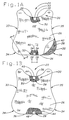
- the puncture resistant garment 20 including the outer moisture vapor permeable and waterproof cover or sleeve 26 as well as the flexible panel 28 of the layered woven sheets 22 is sized and shaped to accommodate the covering of a chest area and an abdominal region of the wearer.
- a top portion 30 of the puncture resistant panel 28 of woven sheets 22 generally defines a U-shaped recess for receiving a lower portion of the neck of the potential wearer.
- the side portions 33, 35 of puncture resistant garment 20 having the flexible sheets 22 of finely woven aramid fibers 24 are generally tapered inwardly to permit movement of the wearer's arms and for added comfort.
- the bottom corner edges 34 of the puncture resistant garment 20 are rounded with the central portion of the garment bottom 36 generally being straight and flat.
- the puncture resistant panel 28 comprised of layers, Fig. 2 of the flexible woven aramid fiber sheets 22 is shaped to be substantially congruent to the shape of the Gore-tex® sleeve 26 covering the panel 28 of sheets 22.
- the shape of the outer edges 38 of the plurality of woven sheets are each congruent with each other as they are positioned in a layered fashion to lie upon each other within the panel 28.
- the plurality of flexible layers of the woven sheets 22 are preferably noninvasively secured to form the puncture resistant panel 28 of such layered sheets.
- Noninvasively securing the woven sheets 22A-L, Fig. 2 together aids in preventing puncture penetration of a sharp object through the panel 28.
- Noninvasive securing in the present invention avoids employing an opening through the panel as opposed to securement through stapling or the like which establishes an open path of lesser resistance for stopping penetration by a sharp object.
- a piece of tape 40 is suitably accomplished by placing a piece of tape 40 around the top sheet 42 and over the bottom sheet 44 in the panel 28 as seen in Figs. 3A-3B.
- a portion 46 of the securement tape 40 secures a top surface of the top sheet 42 in the panel 28 of sheets 22 and another portion 48 of the tape 40 secures to a bottom sheet 44 (See Fig. 1B) of the panel in order to noninvasively secure the plurality of woven sheets together.
- the securement tape 40 secures each of the adjacent edges of the layered woven sheets 22.
- the securement tape 40 secures the edges of the woven sheets 22 at a top location 50 on one side edge of the panel 28 while another piece of the securement tape 40 secures the edges of the layered puncture resistant sheets 22 at another or bottom location 52 on another or bottom side edge of the panel.
- the pieces of securement tape 40 secure the one and the other side edges, preferably top and bottom side edges, of the panel 28 which are positioned on opposing sides of each other on the puncture resistant panel 28.
- An alternative approach to securing the layers of woven sheets 22 together in a principally noninvasive manner may be accomplished by positioning an adhesive to be placed between adjacent of various woven sheets of aramid fibers. It is also contemplated in the present invention that other various approaches to securing or maintaining the alignment of the woven sheets 22 may be accomplished such as through the employment of external clips pinching the layered sheets, lamination along top and/or bottom edges of the sheets or gluing the sheets at preselected locations along the sheet edges.
- the panel 28 preferably contains twelve (12) individually layered sheets, (illustrated as 22A-L Fig. 2) of the finely woven aramid fibers 24, Fig. 7A, 7B.
- fewer of the layered sheets can be suitably employed, wherein at least eight (8) individually layered sheets 22 are generally used to form a puncture resistant panel. Differing numbers of total sheets per panel and differing numbers of panels or sub-panels used for individual puncture resistant garment vests may be suitably employed in accordance with user requirements or desired levels of protection, flexibility and comfort.
- Securement or aligning and positioning of the woven sheets 22 may also be accomplished by means of the outer sleeve 26 encasing the sheets to form the puncture resistant panel 28.
- the outermost covering sleeve 26 of the preferred embodiment is substantially congruent and the same shape as the individual sheets 22 in order to create a tight pit and to position the sheets into proper alignment for forming the puncture resistant panel.
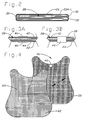
- FIG. 4 an alternative embodiment of a puncture resistant garment 56 and a preferred embodiment of a hybrid or combination puncture resistant and ballistic resistant garment which is shown having an inner puncture resistant panel 58 of layered sheets of woven aramid fibers as described in Figs. 1A-3B, and an outer ballistic resistant panel 60.
- the puncture resistant panel 58 seen in Fig. 4, is preferably of the same layer orientation, dimension, material and weave construction as puncture resistant panel 28 described herein with reference to Figs. 1A-3B.
- the ballistic resistant panel 60 is positioned at the front or outer area of the composite ballistic and puncture resistant garment 56 relative to the wearer of the garment. As seen in Fig.
- the ballistic resistant panel 60 is positioned in front of the puncture resistant panel 58 at the strike face of the vest garment 56.
- the ballistic resistant panel 60 is placed to the front of the garment 56 and away from the body of the wearer relative to the inner puncture resistant panel 58 such that an attacking object e.g. projectile, sharp weapons etc. would initially contact the outer ballistic panel 60.
- Individual outer covers for each of the ballistic resistant and puncture resistant panels as is shown in Fig. 4 is generally not imperative to provide proper protection, thus, it is often preferred that individual puncture resistant panels and ballistic resistant panels are placed in aligned overlying position with a single outer sleeve covering both panels.
- the ballistic resistant panel 60 is constructed of a plurality of sheets of woven fibers 62.
- the ballistic resistant panel 60 is formed of flexible layered sheets of a woven fiber having significantly less than twenty-four (24) warp ends per centimeter and less than twenty-four (24) fill ends per centimeter (60 warp ends per inch).
- the warp ends represent the aramid fibers which extend along the length of the fabric and the fill ends are representative of the other fibers of the weave which are woven in generally a transverse direction to the warp ends.
- the sheets of the ballistic resistant panel 60 of the preferred embodiment are formed of a woven aramid fiber, however ballistic aramid fibers are constructed of filaments having much greater than 13,953,488 filament crossovers per square centimeter (90.000.000 filament crossovers per square inch).
- the structural characteristics of the ballistic resistant panel 60 render it suitable for stopping penetration of a projectile object such as a bullet shot from a firearm. Such characteristics differ from the novel structural characteristics of fiber weave properties combined with particular fiber strength, fiber compound, filament crossover range, break elongation percentage, denier, tenacity and strength described above for the puncture resistant panel whereby such combination enables the puncture resistant panel 28, 58 to protect against and prevent penetration from various knives, blades, shanks, awls and other sharp objects.
- the ballistic resistant panel 60 in the embodiment shown in Fig. 4 is formed of sheets of woven aramid fibers of preferably greater than 200 denier. The woven sheets preferably are formed of aramid Kevlar® fibers in the ballistic resistant panel such as Nos.
- Fibers used in forming ballistic resistant fabrics include Twaron® T-1000 and T-2000 made by AKZO NOBEL, Inc. and Spectra® woven fabrics manufactured by Allied Signal, Inc. Many types of fibers are available for this ballistic resistant construction which includes polyethylene fibers. Moreover, there have been generations of fibers and fabrics made from these fibers which have evolved over the years beginning with the first generation of ballistic nylon; second generation of Kevlar® 29, Kevlar® 49, Twaron and Spectra®; third generation of Twaron T-2000 Microfilament, Kevlar® 129 and Kevlar® LT fabrics; and fourth generation of Araflex TM .
- Such a ballistic resistant panel can be seen in U.S. Patent No. 5,479,659 entitled “Lightweight Ballistic Resistant Garments and Method to Produce Same” issued January 2, 1996 to Bachner and is herein incorporated by reference.
- Such a garment would preferably have an imbalanced weave of fifty-six by sixty-one fibers per centimeter (twenty-two by twenty-four fibers per inch) and would utilize Kevlar® which would provide between 15,503,000 to 46,635,658 crossovers (100 000 000 to 275 000 000 crossovers).
- FIG. 5 an alternative embodiment 62 to the hybrid or combination protective garment which includes a puncture resistant panel 64 and ballistic resistant panel 66 is shown.
- an alternative composite material 68 for the ballistic resistant portion of the vest overlies the puncture resistant panel 64 in order to prevent penetration of a ballistic missile or projectile through the ballistic resistant panel 66 positioned in front of the underlying puncture resistant panel 64.
- the ballistic resistant panel 66 of Fig. 5 is constructed of the relatively looser woven Kevlar® aramid fiber having the properties as described with reference to Fig. 4.
- the composite material or sheet 68 is formed of a metal such as titanium or other suitable very strong metals, as well as, other suitable composite materials that are ballistic resistant such as ceramics, or Spectra Shield®, Gold Shield® and Gold Flex® as well as other reinforced plastics manufactured by Allied Signal Inc. of Morris County, N.J., and other nonwoven composite materials and the like.
- ballistic resistant materials woven and nonwoven are used in the present invention either separately or individually with the puncture resistant panel or in combination with each other and the puncture resistant panel.
- Numerous ballistic resistant panels have been developed utilizing woven aramid fibers or other comparable performance fibers, as well as, composite materials or both which are selectively used in this embodiment for panel 66.
- the hybrid vest or combination puncture resistant garment 62 having added ballistic resistant capabilities in the embodiments of Figs. 4 and 5 are shown without a sleeve or Gore-tex® type cover for the individual puncture resistant panel 66 and the ballistic resistant panel 66.
- the single sleeve covering accordingly, has an interior region having substantially the same shape and configuration of the ballistic resistant vest panel 66 and puncture resistant vest panel 64, which are substantially congruent having substantially the same shape to each other.
- the hybrid garment of the present invention having a ballistic resistant panel positioned at a strike face region in front of and overlying the combined puncture resistant panel described in Figs. 4 and 5, has been shown to have complimentary capabilities whereby the puncture resistant panel has limited ballistic resistant capabilities and the ballistic resistant panel has certain capabilities in protecting against broad blade slashing and cutting.
- FIG. 6 a side elevational view representative of a testing operation for a puncture resistant garment 20 of the present invention is shown with a base of ordinance gelatin 74 underlying the protective puncture resistant garment 20 to be tested.
- a sharp edged object 76 such as a knife, shank, ice pick, awl or the like is initially positioned at a preselected height and is associated with or attached to a weighted object 78 or weighted apparatus to guide the weighted object having a preselected weight.
- the sharp edged object 76 secured to the weight 78 which is initially held into position by a brace or other suitable guiding means at a particular height, is dropped or released, thereby enabling the weighted object 78 to fall whereby the sharp edged object 76 impacts with the protective garment 20 being tested.
- the ordinance gelatin base 74 is formed to a composition to emulate a resilient reaction of a human torso thereby providing realistic and accurate test results for the protective garment 20 or puncture resistant panel 28 overlying the ordinance gelatin base 74. The impact of the sharp edged object 76 upon the protective garment 20 will cause garment 20 to resiliently move and respond to the forces impacting thereon.
- the underlying ordinance gelatin 74 provides for realistic testing of puncture resistant items under various tests including the California ice pick test. Such testing was carried out in accordance with The State of California Specification 8470-8BS-001, para. 3.3, dated Aug. 1988. The test samples selectively are impacted with an ice pick 17.8 cm (7") long by 0.414 cm (0.163") in diameter having a hardness of RC-44, weighed to 7.35 Kg (16.20 pounds) and dropped from a height of 152.6 cm (60.08 inches).
- This California ice pick test utilizes a firm clay base which is less resilient than the gelatin base 74 of the present invention and is less representative of a human body than the gelatin.
- This firmer clay base results in the protective garment incurring relatively higher shear from a given impact from a sharp object than if the same protective garment was overlying the gelatin base of the present invention which is more resilient.
- the clay base provides more conservative and lower results potentially leading to even thicker and more bulky protective garments than if the more realistic gelatin base of the present invention was used.
- the puncture resistant panel 28 described herein with reference to Figs. 1A-3B and Figs 7A, 7B, 8 and 9 has been tested using the parameters of the California ice pick test while employing an ordinance gelatin backing to generate results resembling actual field performance.
- a puncture resistant panel 28 having the weave and composition described herein, with thirty-two (32) woven sheets of the aramid fiber segmented into sub-panels See Fig. 8
- the flexible and concealable puncture resistant garment of the present invention has been shown to withstand the California ice pick test using an ice pick and a stiff shafted Stanley® tools awl, model 69-122, at 11.213 meter-Kilograms (81.1 foot-pounds).
- the puncture resistant panel 28 of the present invention has been able to withstand such an ice pick at 11.213 meter-Kilograms (81.1 foot pounds) for the California ice pick test using an ordinance gelatin backing in which as few as twenty-eight (28) layered sheets of 28 fibers per centimeter x 28 fibers per centimeter (70 fibers per inch x 70 fibers per inch) woven fabric are employed in the panel.
- the puncture resistant garment of the present invention due to the combination of its weave with the woven fiber composition, properties and characteristics described herein as well as the arrangement and securement of the woven sheets in forming various puncture resistant panels and sub-panels, provides optimum protection against stabbings, slashings and the like at various protection levels while being flexible, lightweight, wearable, breathable and concealable.
- the weight and thickness of the protective puncture resistant garment of the present invention may selectively vary depending on the desired level of protection.
- a puncture resistant garment 20 of the present invention having approximately twelve (12) woven sheets in a panel 28 as seen in Fig.
- a garment employing twenty-two (22) woven sheets of such aramid material weighing 2.83 Kg/m 2 (0.58 pounds per square foot) and having a thickness of only 0.432 cm (0.17 inches) has been shown to stop an awl at 9.82 meter-Kilograms (seventy-one (71) foot pounds), an ice pick at 10.23 meter-Kilograms (seventy-four (74) foot-pounds) and a boning knife at 2.49 meter-Kilograms (eighteen (18) foot-pounds).
- the garment of the present invention when employing thirty-two (32), Fig.
- a method of testing the puncture resistance of a protective garment involves the steps of (1) placing the protective garment 20 or puncture resistant panel 28 to overlie a base 74 constructed of ordinance gelatin; (2) securing a sharp edged object 76 to a weight 78; (3) positioning the sharp edged object 76 secured to the weight 78 at a distance above the puncture resistant garment 20; and (4) releasing the sharp edged object 76 secured to the weight 78 to fall providing a sharp edge of the sharp edged object 76 to impact the protective garment 20 enabling the ordinance gelatin base 74 underlying the protective garment 20 to resiliently move and respond to the impact from the sharp edged object 76 impacting onto the protective garment 20.
- the preferred method includes the step of positioning the protective garment 20 to lie substantially flat over the base of ordinance gelatin 74.
- the garment 20 having a single preselected thickness is positioned over the ordinance gelatin base 74 to receive the impact of the free falling knife, shank, ice pick, awl or other sharp object 76.
- the weight attached to the sharp object 76 is generally at least 7.26 Kg (16.0 pounds) and is dropped with the object at a preselected height of approximately 1.524 meters (5.0 feet).
- the ordinance gelatin used in employing the method of testing is preferably a Knox type 250A gelatin, however other suitable gelatin types may be used.
- the block of ordinance gelatin 74 used as the base to simulate actual performance for testings of the overlying vest 20 is constructed of a solution of the dehydrated Knox 250A gelatin which is mixed with water.
- the solution of dehydrated gelatin and water is first initially cooled down prior to elevating its temperature and stirring it.
- the mixed solution is then heated to elevate the temperature and the solution is stirred during preparation.
- the solution is subsequently cooled for 24 hours until it solidifies and thickens. Fractures in the newly formed gelatin block are then repaired to reuse the base 74 reheating the gelatine and mixing more solution into the existing solution and resolidifying the base 74.
- the gelatin base 74 is formed into a block which is approximately 10.16 cm (four (4) inches) in thickness, however the block may selectively be formed at a larger thickness. It is desirable to form the gelatin base 74 in such a manner as to have a top surface or strike face region on the gelatin base 74 which have dimensions of at least 15 cm x 15 cm (six (6) inches x six (6) inches) in area and thus, a suitable container to enable the forming of the base having such dimensions is employed when solidifying the ordinance gelatin.
- Fig 7A an enlarged view representative of a balanced weave for one of the plurality of woven sheets 22 of aramid fibers in the puncture resistant panel 28.
- the weave is balanced as shown in Fig 7A, since the number of warp ends 80 of the aramid fibers 24 placed in a direction along the length of the fabric sheet matches the same number of fill ends 82 of the aramid fibers which run in a transverse direction to the warp ends.
- the weave of the puncture resistant layered sheets contains at least 24 warp end aramid fibers per cm (60 fill end aramid fibers per inch) across the length of the fabric sheet 22 and at least 24 fill end aramid fibers per cm (60 fill end aramid fibers per inch) intersecting with the warp ends.
- a 28 fibers per centimeter warp end (70 fibers per inch warp end) x 28 fibers per cm fill end (70 fibers per inch fill end) weave is employed in the individually woven sheets 22 of aramid fibers described in Figs. 1A, 1B and 7A.
- Each individual woven sheet 22 preferably used has a weight of approximately 0.1290 Kg/m 2 (3.8 ounces per square yard) and has a thickness of only 0.0178 cm (.007 inches (7 mils)).
- FIG. 7B An alternative weave arrangement for the puncture resistant layered woven sheets 22 of aramid fibers 24 is shown in Fig. 7B, in which the warp ends 84 and fill ends 86 of the aramid fibers are imbalanced in number.
- the number of warp ends 84 per given length (inch) of the aramid fibers is greater than the number of fill ends 86 for the same given length.
- the imbalanced weave has more warp ends 84 extending along the length of the sheet 22 fabric than fill ends 86 weaved across the warp ends.
- the material used to enable the 28 x 28 aramid fibers per centimeter weave (70 x 70 aramid fibers per inch weave) described in Fig. 7A and also used in the imbalanced weave of Figs. 7B preferably is Kevlar® 159 developed by DuPont Company, of Wilmington, Delaware. Kevlar® 159,200 denier, has a break elongation of 3.45%, a filament crossovers of just over 13,302,752 (87.000.000 crossovers) and has a tenacity of 27.0 grams per denier.
- the modulus of the fiber preferably employed in the present invention is 730 grams/denier.
- aramid fibers may selectively be used to enable an acceptable weave for proper puncture resistance wherein such aramid fibers are at least 200 denier, have a break elongation of at least 3.45% and have a tenacity of at least 27.0 grams per denier.
- FIG. 8 a sectional side view of an embodiment of the invention illustrating a puncture resistant panel 88 being comprised of three individual sub-panels 90a, 90b, and 90c.
- a puncture resistant panel 88 being comprised of three individual sub-panels 90a, 90b, and 90c.
- the puncture resistant panel 28 depicted in Fig. 8 has a total thirty-two (32) sheets 22 of woven aramid fibers.
- the panel 88 is segmented into three sub-panels 90a, 90b, and 90c.
- Top sub-panel 90a has ten layered sheets formed of woven Kevlar® 159 fibers which are stitched together
- central sub-panel 90b has twelve (12) sheets of woven fibers stitched to form the sub-panel
- bottom sub-panel 90c also has ten (10) sheets of woven fabric which are stitched at preselected locations to form the bottom sub-panel.
- the three sub-panels 90a, 90b, and 90c depicted in Fig. 8, are noninvasively secured together by tape 40 in order to prevent sliding movement of the sub-panels.
- the securing tape 40 is adhered onto a portion of the top sheet of the top sub-panel, is extended to and adheres to the side edge of each sub-panel 90a, 90b, and 90c comprising the puncture resistant panel 88 and is also adhered to the bottom sub-panel at a corresponding bottom portion of the bottom puncture resistant woven sheet of bottom sub-panel 90c.
- the outer covering sleeve 92 is snugly positioned about the noninvasively secured sub-panels 90a-c.
- FIG. 9 an exploded and partially schematic view of the puncture resistant garment of the present invention is shown having three sub-panels 90a, 90b and 90c, in which the woven fiber sheets for each individual sub-panel are secured together by stitches of a suitable aramid fiber in order to form the distinctly identifiable sub-panel.
- the stitches employed are made of a sufficiently strong fibrous material to secure and maintain the proper aligned positioning of the overlying congruently shaped woven sheets.
- the aramid fiber employed for such stitching in the present invention preferably is constructed of a Kevlar® material.
- Each of the individual sub-panels 90a, 90b, and 90c has its puncture resistant woven sheets invasively secured together by four separate lines of stitches.
- top sub-panel 90a as seen in Fig. 9, is secured by four lines of stitches 91a, 91b, 91c and 91d, the woven sheets of central sub-panel 90b are invasively secured together by stitches 93a, 93b, 93c and 93d and bottom sub-panel 90c its puncture resistant sheets are secured by stitches 95a, 95b, 95c and 95d.
- Fig. 9 is representative of a puncture resistant panel with the outer covering sleeve removed and is exploded into the three sub-panels 90a, 90b and 90c. Additionally, in Fig. 9 the tight weave of the aramid fibrous sheets was not emphasized, in an effort to better show the stitching and its relative positioning on the sub-panels 90a, 90b and 90c. Of course, as previously described, the minimal stitching for the sub-panels directly secures the woven aramid fibrous sheets into forming the identified sub-panels.
- Each line of the stitches for each sub-panel 90a-c are spaced apart from the edge of their respective sub-panel, but are also positioned in the four corners of the sub-panel closer in distance to the respective edge than to the central portion 92a, 92b and 92c of the sheets which they secure, beneath the overlying cover sleeve as seen in Fig. 10.
- the sub-panels 90a, 90b and 90c formed of stitched sheets of woven aramid fibrous material described in Fig. 9, are shown in an assembled position depicting the stitching for each of the overlying sub-panels.
- the stitches 91a, 91b, 91c and 91d of sub panel 90a, and the stitches 93a, 93b, 93c and 93d of sub-panel 90b, as well as the stitches 95a, 95b, 95c and 95d of sub-panel 90c are all positioned to be out of alignment with each other when the sub-panels 90a-c are in the assembled position for use when they overlie one another.
- the stitches of the first sub-panel 90a, the stitches of the second sub-panel 90b, and the stitches of the third sub-panel 90c are clearly spaced apart from each other when the sub-panels are assembled in the overlying position as depicted in Fig. 10.
- the stitches of each sub-panel are each spaced apart along the surface of their respective sub-panel. The nonalignment of the stitches from one panel to another does not provide any area of least resistance through the entire panel unlike that which would occur should the stitches be in alignment.
- FIG. 11 another alternative embodiment of the present invention is shown illustrating three sub-panels 60A, 58 and 60B in which a puncture resistant panel 58 is positioned between a top or front ballistic resistant panel 60A and an underlying bottom or back ballistic resistant panel 60B.
- a desired structure of the present invention is maintained by placing the bottom or back ballistic resistant panel 60B in a position where it will be closest to the body of the wearer.
- a key aspect of the present invention shown in the particular configuration of panels in Fig. 11 is accomplished by having the front ballistic panel 60A positioned at the strike face of the garment to receive the force of the impacting object.
- Another aspect of the present invention includes a method for assembling a puncture and ballet resistant garment.
- the method of assembling such a puncture resistant garment is accomplished by the steps of: (1) assembling a plurality of woven sheets constructed of aramid fibers 24 to overlie one another in which the woven sheets 24 are constructed of aramid fibers in which said woven sheets have a weave of at least 24 aramid fibers per cm (60 aramid fibers per inch) in one direction and at least 24 aramid fibers per cm (60 aramid fibers per inch) in another direction which is transverse to the one direction and in which the aramid fibers have at least of the following characteristics : the aramid fibers being constructed of filaments which provide from 7,751,934 up to 13,953,488 filament crossovers per square cm (50 000 000 to 90 000 000 filament crossovers per square inch) in the plurality of woven sheets and (2) securing the plurality of woven sheets 24 together forming the puncture resistant panel 28.
- the preferred method includes the step of taping adjacent edges (Fig. 3A, 3B) together of the woven sheets together. Alternatively, the adjacent edges of the woven sheets are selectively glued together. Securement of the woven sheets to form the puncture resistant panel includes the step of placing the plurality of woven sheets into a sleeve 26 constructed of moisture vapor permeable and water proof material and in which the sleeve has an interior shape and a dimension which is substantially the same as the shape and dimension of the plurality of woven sheets 22 which are inserted therein.
- a further approach to securing the individual woven sheets together to form a puncture resistant panel includes the step of stitching less than the total number of the woven sheets together by a line of stitches, 91A-91D, 93A-D, 95A-D which are positioned proximate to a side edge of the woven sheets thereby forming sub-panels 90A, 90B, 90C in position to overlie one another.
- a line of stitches 91A-91D, 93A-D, 95A-D which are positioned proximate to a side edge of the woven sheets thereby forming sub-panels 90A, 90B, 90C in position to overlie one another.
- four lines of stitches are each positioned in lower right, lower left, upper right and upper left corner regions of the woven sheets to secure them together.
- the aramid fiber which is woven into the layered sheets is no more than 200 denier.
- the aramid fiber used in the preferred embodiment is Kevlar® 159, however, other suitable fiber to be used preferably will have a tenacity of at least 27.0 grams/denier and a break elongation of at least 3.45%.
- the weave provided in the individual puncture resistant sheets in the panel 28 have at least twenty-four warp ends 80 (sixty ends per inch) and at least twenty-four fill ends 82 (sixty ends per inch) per centimeter, with a 28 x 28 aramid fibers per cm balanced weave optimally being employed, Fig. 7A.
- the warp 84 and fill ends 86 of the aramid fibers forming the puncture resistant panel are selectively imbalanced in number whereby the warp ends of the aramid fibers exceed the number of fill ends of the aramid fiber.
- the method of forming a puncture and bullet resistant vest includes the step of positioning a ballistic resistant panel on top of the puncture resistant panel in which the ballistic resistant panel is selectively constructed of a woven fiber having filaments with fewer than 24 warp ends and fill ends per centimeter (sixty ends per inch) while also having generously more than 13,953,488 filament crossovers per square cm (90.000.000 filament crossovers per square inch) for the fibers of the ballistic resistant panel.
- An unwoven composite material formed of a metallic sheet member, a ceramic or titanium composite material or Gold Flex® material maybe alternatively employed which is positioned to overlie the puncture resistant panel and/or woven ballistic panel to prevent penetration of a ballistic missile through the ballistic resistant panel.
- Two puncture resistant panels 58A, 58B are selectively positioned to each overlie both sides of the ballistic resistant panel 60 thereby positioning the ballistic resistant panel between the two puncture resistant panels, as seen in Fig. 11.
Landscapes
- Engineering & Computer Science (AREA)
- Ceramic Engineering (AREA)
- General Engineering & Computer Science (AREA)
- Chemical & Material Sciences (AREA)
- Textile Engineering (AREA)
- Professional, Industrial, Or Sporting Protective Garments (AREA)
- Aiming, Guidance, Guns With A Light Source, Armor, Camouflage, And Targets (AREA)
- Woven Fabrics (AREA)
Claims (32)
- Kombiniert durchstichfestes und kugelsicheres Kleidungsstück (56), das umfasst:eine Vielzahl flexibler Schichten gewebter Lagen (22), die so angeordnet sind, dass sie übereinanderliegen und eine durchstichfeste Bahn (58) bilden, wobei die Vielzahl gewebter Lagen (22) aus Aramid-Fasern (24) besteht und die gewebten Lagen (22) eine Bindung von wenigstens 24 Aramid-Fasern pro Zentimeter (60 Aramid-Fasern pro Inch) in einer Richtung und wenigstens 24 Aramid-Fasern pro Zentimeter (60 Aramid-Fasern pro Inch) in einer anderen Richtung quer zu der Richtung haben, und wobei die Aramid-Fasern (24) aus Fäden aufgebaut sind, die von 7 751 934 bis zu 13 953 488 Faden-Verkreuzungen pro Quadratzentimeter (50 000 000 bis 90 000 000 Verkreuzungen pro Quadratinch) in der Vielzahl gewebter Lagen (22) bewirken, wobei die Faden-Verkreuzungen hergeleitet werden, indem die Anzahl von Fäden in einer Faser mit der Anzahl von Fasern pro Zentimeter (Inch) in der Bindung in der ersten Richtung multipliziert wird und diese Menge mit der Anzahl von Fäden in einer kreuzenden Faser mit der Anzahl von kreuzenden Fasern pro Zentimeter (Inch) in der Bindung in der kreuzenden Richtung multipliziert wird; undeine kugelsichere Bahn (60), die aus geschichteten Lagen (62) einer gewebten Faser aufgebaut ist, wobei die Lagen (62) weniger als 24 Kettfäden und weniger als 24 Schussfäden pro Zentimeter (60 Fäden pro Inch) der gewebten Faser aufweisen, und wobei die gewebte Faser aus Fäden aufgebaut ist, die mehr als 13 953 488 Faden-Verkreuzungen pro Quadratzentimeter (90 000 000 Faden-Verkreuzungen pro Quadratinch) der kugelsicheren Bahn (60) aufweisen.
- Kombiniert durchstichfestes und kugelsicheres Kleidungsstück (56) nach Anspruch 1, wobei die Aramid-Faser (24) der durchstichfesten Vielzahl gewebter Lagen (22) der Bahn (58) annähernd 200 Denier hat.
- Kombiniert durchstichfestes und kugelsicheres Kleidungsstück (56) nach Anspruch 1, wobei es sich bei der Aramid-Faser (24) der Vielzahl gewebter Lagen (22) der durchstichfesten Bahn (58) um Kevlar® handelt.
- Kombiniert durchstichfestes und kugelsicheres Kleidungsstück (56) nach Anspruch 1, wobei die Festigkeit der Aramid-Faser (24) der Vielzahl gewebter Lagen (22) der durchstichfesten Bahn (58) wenigstens 27,0 Gramm/Denier beträgt.
- Kombiniert durchstichfestes und kugelsicheres Kleidungsstück nach Anspruch 1, wobei die Aramid-Faser (24) der Vielzahl gewebter Lagen (22) der durchstichfesten Bahn (58) eine Bruchdehnung von wenigstens 3,45% aufweist.
- Kombiniert durchstichfestes und kugelsicheres Kleidungsstück (56) nach Anspruch 1, wobei die Bindung der Vielzahl gewebter Lagen (22) der durchstichfesten Bahn (58) wenigstens 28 Kettfäden (80, 84) pro Zentimeter (70 Fäden pro Inch) und wenigstens 28 Schussfäden (82, 86) pro Zentimeter (70 Fäden pro Inch) enthält.
- Kombiniert durchstichfestes und kugelsicheres Kleidungsstück (56) nach Anspruch 1, das eine Einrichtung zum Befestigen der Vielzahl gewebter Lagen (22) aneinander zum Ausbilden der durchstichfesten Bahn (58) enthält.
- Kombiniert durchstichfestes und kugelsicheres Kleidungsstück (56) nach Anspruch 7, wobei die Befestigungseinrichtung ein Stück Band (40) enthält, um die gewebten Lagen (22) nichtinvassiv zu befestigen und sie ausgerichtet zu halten, wobei ein Abschnitt des Bandes (40) eine Oberseite einer oberen Lage (42) der Vielzahl von Lagen (22) befestigt und ein anderer Abschnitt des Bandes eine Unterseite einer unteren Lage (44) der durchstichfesten Bahn (58) aus gewebten Lagen (22) befestigt, so dass die Vielzahl gewebter Lagen aneinander befestigt werden.
- Kombiniert durchstichfestes und kugelsicheres Kleidungsstück (56) nach Anspruch 7, wobei die Befestigungseinrichtung das Befestigen einer Vielzahl aneinandergrenzender Kanten der Vielzahl gewebter Lagen (22) an einer Position an einer Seitenkante der durchstichfesten Bahn (58) und das Befestigen einer Vielzahl aneinandergrenzender Kanten der Vielzahl gewebter Lagen (22) an einer anderen Position an einer anderen Seitenkante der durchstichfesten Bahn (58) einschließt.
- Kombiniert durchstichfestes und kugelsicheres Kleidungsstück (56) nach Anspruch 7, wobei die Befestigungseinrichtung einen Klebstoff enthält, der zwischen aneinandergrenzenden gewebten Lagen (22) angeordnet ist.
- Kombiniert durchstichfestes und kugelsicheres Kleidungsstück nach Anspruch 7, wobei die Befestigungseinrichtung eine Hülle (26) enthält, die aus wasserdichtem und wasserdampfdurchlässigem Material aufgebaut ist und die durchstichfeste Bahn (58) umschließt.
- Kombiniert durchstichfestes und kugelsicheres Kleidungsstück (56) nach Anspruch 7, wobei die durchstichfeste Bahn (58) wenigstens acht der gewebten Lagen (22) enthält.
- Kombiniert durchstichfestes und kugelsicheres Kleidungsstück (56) nach Anspruch 1, wobei weniger als eine Gesamtzahl der Vielzahl von Lagen (22) mit der Befestigungseinrichtung aneinander befestigt sind, um eine Teilbahn (90) in der durchstichfesten Bahn (58) zu bilden.
- Kombiniert durchstichfestes und kugelsicheres Kleidungsstück (56) nach Anspruch 13, wobei die weniger als die Gesamtzahl ausmachenden der Vielzahl von Lagen (22) mit Nähten (91, 93, 95) aneinander befestigt sind.
- Kombiniert durchstichfestes und kugelsicheres Kleidungsstück (56) nach Anspruch 14, wobei die Nähte vier separate Linien von Nähten (91A-D) enthalten, wobei eine der Linien jeweils in einem unteren rechten, einem unteren linken, einem oberen rechten und einem oberen linken Abschnitt der Teilbahn (90A) in Bezug auf einen Mittelabschnitt der Teilbahn mit weniger gewebten Lagen als der Gesamtzahl gewebter Lagen (22) angeordnet ist.
- Kombiniert durchstichfestes und kugelsicheres Kleidungsstück (56) nach Anspruch 15, wobei jede Linie von Nähten (91A-D) von einer Kante der Lagen (22) beabstandet ist und des Weiteren näher an der Kante einer der Bahnen als an dem Mittelabschnitt (92) der Lage angeordnet ist.
- Kombiniert durchstichfestes und kugelsicheres Kleidungsstück (56) nach Anspruch 15, das wenigstens zwei Teilbahnen (90A, 90B) enthält, wobei die Nähte (91A-D) einer ersten Teilbahn (90A) verschoben zu den Nähten (93A-D) einer zweiten Teilbahn (90B) angeordnet sind, wobei die Teilbahnen so angeordnet sind, dass sie übereinander liegen.
- Kombiniert durchstichfestes und kugelsicheres Kleidungsstück (56) nach Anspruch 17, wobei die Nähte (91A-D, 93A-D) der ersten Teilbahn (90A) und der zweiten Teilbahn (90B) voneinander entlang der ersten und der zweiten Teilbahn beabstandet sind, wenn die erste und die zweite Teilbahn (90A, 90B) in übereinander liegende Position gebracht sind.
- Kombiniert durchstichfestes und kugelsicheres Kleidungsstück (56) nach Anspruch 1, das zwei kugelsichere Bahnen (60A, 60B) enthält, wobei die durchstichfeste Bahn (58) zwischen den zwei kugelsicheren Bahnen (60A, 60B) angeordnet ist.
- Kombiniert durchstichfestes und kugelsicheres Kleidungsstück (56) nach Anspruch 1, das zwei durchstichfeste Bahnen (58) enthält, wobei die kugelsichere Bahn (56) zwischen den zwei durchstichfesten Bahnen (58) angeordnet ist.
- Kombiniert durchstichfestes und kugelsicheres Kleidungsstück (56) nach Anspruch 1, wobei die kugelsichere Bahn (60) an einer Aufschlagfläche des Kleidungsstücks angeordnet ist.
- Kombiniert durchstichfestes und kugelsicheres Kleidungsstück (56) nach Anspruch 1, wobei die kugelsichere Bahn (60) eine Vielzahl von Lagen (62) aus gewebten Aramid-Fasern mit mehr als 200 Denier enthält.
- Kombiniert durchstichfestes und kugelsicheres Kleidungsstück (56) nach Anspruch 1, wobei die kugelsichere Bahn (60) ein Blechelement (68) enthält.
- Verfahren zum Zusammensetzen des kombiniert durchstichfesten und kugelsicheren Kleidungsstücks (56) nach Anspruch 1, das die folgenden Schritte umfasst:Zusammensetzen der Vielzahl gewebter Lagen (22), die aus Aramid-Fasern (24) aufgebaut sind, so dass sie übereinander liegen;Befestigen der Vielzahl gewebter Lagen (22) aneinander, so dass die durchstichfeste Bahn (58) entsteht; undAnordnen der kugelsicheren Bahn (60), so dass sie über der durchstichfesten Bahn (58) liegt, um das Durchdringen eines Geschosses durch die kugelsichere Bahn zu verhindern.
- Verfahren nach Anspruch 24, das das Anordnen der durchstichfesten Bahn (58) zwischen zwei kugelsicheren Bahnen (60A, 60B) einschließt.
- Verfahren nach Anspruch 24, das das Anordnen von zwei durchstichfesten Bahnen (58) zueinander einschließt, so dass sie jeweils über beiden Seiten der kugelsicheren Bahn (60) liegen, um so die kugelsichere Bahn (60) zwischen den zwei durchstichfesten Bahnen (58) anzuordnen.
- Verfahren nach Anspruch 24, wobei die kugelsichere Bahn (60) an einer Aufschlagfläche des Kleidungsstücks (56) angeordnet wird.
- Verfahren nach Anspruch 24, wobei die Vielzahl von Lagen (62) der kugelsicheren Bahn (60) aus gewebten Aramid-Fasem mit mehr als 200 Denier besteht.
- Verfahren nach Anspruch 24, wobei die kugelsichere Bahn (60) ein Blechelement enthält.
- Kombiniert durchstichfestes und kugelsicheres Kleidungsstück nach Anspruch 1, wobei die Aramid-Fasern (24) der gewebten Lagen (22) der durchstichfesten Bahn (58) eine Bruchdehnung von mehr als 3 Prozent aufweisen.
- Kombiniert durchstichfestes und kugelsicheres Kleidungsstück nach Anspruch 30, wobei die Aramid-Fasern (24) der gewebten Lagen (22) der durchstichfesten Bahn. (58) eine Festigkeit von mehr als 23,8 Gramm pro Denier bewirken.
- Kombiniert durchstichfestes und kugelsicheres Kleidungsstück nach Anspruch 1, wobei die Aramid-Fasern (24) der gewebten Lagen (22) der durchstichfesten Bahn (58) eine Festigkeit von mehr als 23,8 Gramm pro Denier bewirken.
Applications Claiming Priority (3)
| Application Number | Priority Date | Filing Date | Title |
|---|---|---|---|
| US691251 | 1996-08-02 | ||
| US08/691,251 US5960470A (en) | 1996-08-02 | 1996-08-02 | Puncture resistant protective garment and method for making same |
| PCT/US1997/013740 WO1998005917A1 (en) | 1996-08-02 | 1997-08-04 | Puncture resistant protective garment and method for making and testing the same |
Publications (3)
| Publication Number | Publication Date |
|---|---|
| EP0914586A1 EP0914586A1 (de) | 1999-05-12 |
| EP0914586A4 EP0914586A4 (de) | 1999-10-20 |
| EP0914586B1 true EP0914586B1 (de) | 2002-08-21 |
Family
ID=24775754
Family Applications (1)
| Application Number | Title | Priority Date | Filing Date |
|---|---|---|---|
| EP97938116A Expired - Lifetime EP0914586B1 (de) | 1996-08-02 | 1997-08-04 | Stichfestes kleidungsstück und herstellungsverfahren dafür |
Country Status (6)
| Country | Link |
|---|---|
| US (4) | US5960470A (de) |
| EP (1) | EP0914586B1 (de) |
| AU (1) | AU4051997A (de) |
| CA (1) | CA2261746C (de) |
| DE (1) | DE69714852T2 (de) |
| WO (1) | WO1998005917A1 (de) |
Families Citing this family (79)
| Publication number | Priority date | Publication date | Assignee | Title |
|---|---|---|---|---|
| DE4423194A1 (de) * | 1994-07-01 | 1996-01-04 | Triumph International Ag | Verfahren zur Herstellung von Ausformungen in Flächengebilden aus aromatischen Polyamiden |
| US6133169A (en) * | 1998-03-20 | 2000-10-17 | E. I. Du Pont De Nemours And Company | Penetration-resistant ballistic article |
| US6162746A (en) * | 1998-09-29 | 2000-12-19 | E. I. Du Pont De Nemours And Company | Hybrid protective composite |
| TWI227197B (en) * | 1998-12-21 | 2005-02-01 | Du Pont | Hybrid protective composite |
| EP1144740B1 (de) * | 1999-01-18 | 2003-10-22 | Teijin Twaron GmbH | Penetrationsresistentes material mit einem gewebe mit hohem linearem dichteverhältnis zwischen zwei gruppen von garnen |
| US6233737B1 (en) * | 1999-01-29 | 2001-05-22 | Safari Land Ltd., Inc. | Concealable ballistic vest |
| US6272687B1 (en) * | 2000-02-11 | 2001-08-14 | Frank W. Cunningham | Puncture proof surgical gloves |
| ES2292447T3 (es) * | 1999-03-12 | 2008-03-16 | Simula, Inc. | Blindaje de tejido perfeccionado. |
| GB9927674D0 (en) * | 1999-11-23 | 2000-01-19 | Aegis Eng Ltd | Protective material |
| RU2155313C1 (ru) * | 1999-11-24 | 2000-08-27 | Федоров Виктор Александрович | Тканевая бронепанель, тканевый бронемодуль и бронезащитная ткань |
| AT408918B (de) * | 2000-03-14 | 2002-04-25 | Astron Elastomerprodukte Ges M | Mehrschichtmaterial zum schutz von körperteilen |
| GB0014128D0 (en) * | 2000-06-10 | 2000-08-02 | Lorica Research Limited | Composite material and use therof |
| US6475936B1 (en) * | 2000-06-13 | 2002-11-05 | E. I. Du Pont De Nemours And Company | Knife-stab-resistant ballistic article |
| US6415446B1 (en) * | 2000-07-05 | 2002-07-09 | The United States Of America As Represented By The Secretary Of The Army | Protective glove |
| EP1311798A4 (de) | 2000-08-16 | 2006-11-22 | Second Chance Armor Inc | Mehrteiliges stick- und beschusssicheres kleidungsstück und zugehöriges verfahren |
| DE20015335U1 (de) | 2000-09-04 | 2000-11-09 | Reimer, Martin, 38102 Braunschweig | Oberkörperschutzausstattung |
| US6704934B2 (en) * | 2000-12-07 | 2004-03-16 | Ted Graham | Ballistic vest |
| US6507486B2 (en) | 2001-04-10 | 2003-01-14 | Xybernaut Corporation | Wearable computer and garment system |
| US6651543B2 (en) * | 2001-08-28 | 2003-11-25 | Andrew D. Park | Lightweight soft body-armor product |
| US6389594B1 (en) * | 2001-08-30 | 2002-05-21 | Israel Military Industries Ltd. | Anti-ballistic ceramic articles |
| US6681765B2 (en) | 2001-12-18 | 2004-01-27 | Sheree H. Wen | Antiviral and antibacterial respirator mask |
| EP1476711B2 (de) † | 2002-02-08 | 2009-12-02 | Teijin Twaron GmbH | Stichgeschütztes und antiballistisches material und verfahren zu dessen herstellung |
| US6845513B2 (en) * | 2002-03-07 | 2005-01-25 | Pacific Safety Products Inc. | Ballistic body armor employing combination of desiccant and ballistic material |
| US6846758B2 (en) | 2002-04-19 | 2005-01-25 | Honeywell International Inc. | Ballistic fabric laminates |
| US6841492B2 (en) * | 2002-06-07 | 2005-01-11 | Honeywell International Inc. | Bi-directional and multi-axial fabrics and fabric composites |
| US6922847B2 (en) * | 2002-07-26 | 2005-08-02 | Second Chance Body Armor, Inc. | Multipurpose thin and lightweight stab and ballistic resistant body armor and method |
| US20040048109A1 (en) * | 2002-09-05 | 2004-03-11 | Safeboard Ab | Penetration resistant article |
| US8245319B2 (en) * | 2002-09-10 | 2012-08-21 | American Development Group International, Llc | Lightweight fabric based body armor |
| US6862971B2 (en) | 2002-12-17 | 2005-03-08 | Texas Tech University | Ballistic protection composite shield and method of manufacturing |
| US20050005762A1 (en) * | 2003-02-10 | 2005-01-13 | Lujan Dardo Bonaparte | Armored assembly |
| US7226878B2 (en) | 2003-05-19 | 2007-06-05 | The University Of Delaware | Advanced body armor utilizing shear thickening fluids |
| US6966261B2 (en) * | 2003-05-20 | 2005-11-22 | Alliant Techsystems Inc. | Fuze explosive ordnance disposal circuit |
| US6764764B1 (en) | 2003-05-23 | 2004-07-20 | Honeywell International Inc. | Polyethylene protective yarn |
| US20040237763A1 (en) * | 2003-06-02 | 2004-12-02 | Ashok Bhatnagar | Corrugated ballistic armor |
| US7340779B2 (en) * | 2003-07-01 | 2008-03-11 | E.I. Du Pont De Nemours And Company | Flexible spike/ballistic penetration-resistant articles |
| US7426753B1 (en) * | 2003-09-16 | 2008-09-23 | Paul Brent Rivers | Protective garment |
| US20090142557A1 (en) | 2003-11-26 | 2009-06-04 | Hardin Montgomery G B | Material for Providing Impact Protection |
| US7216576B2 (en) * | 2004-02-27 | 2007-05-15 | James Jackson Milham Henry | Trampoline responsive armor panel |
| US7288493B2 (en) * | 2005-01-18 | 2007-10-30 | Honeywell International Inc. | Body armor with improved knife-stab resistance formed from flexible composites |
| US20070293109A1 (en) * | 2005-06-16 | 2007-12-20 | Ashok Bhatnagar | Composite material for stab, ice pick and armor applications |
| US7687412B2 (en) * | 2005-08-26 | 2010-03-30 | Honeywell International Inc. | Flexible ballistic composites resistant to liquid pick-up method for manufacture and articles made therefrom |
| US7601416B2 (en) * | 2005-12-06 | 2009-10-13 | Honeywell International Inc. | Fragment and stab resistant flexible material with reduced trauma effect |
| US8673198B2 (en) * | 2006-02-18 | 2014-03-18 | Honeywell International Inc | Method of making improved ballistic products |
| US7919418B2 (en) * | 2006-09-12 | 2011-04-05 | Honeywell International Inc. | High performance ballistic composites having improved flexibility and method of making the same |
| US20120174275A1 (en) * | 2006-10-24 | 2012-07-12 | Carlson Richard A | Female armor system |
| US8652570B2 (en) * | 2006-11-16 | 2014-02-18 | Honeywell International Inc. | Process for forming unidirectionally oriented fiber structures |
| US8661572B2 (en) | 2007-09-06 | 2014-03-04 | Artisent, Llc | Helmet edge band |
| US20090090023A1 (en) * | 2007-10-01 | 2009-04-09 | Kyle Daniel Rackiewicz | Snakebite protective footwear |
| US9046323B2 (en) * | 2008-02-25 | 2015-06-02 | Safariland, Llc | Ballistic package for soft body armor |
| US7665149B2 (en) * | 2008-05-14 | 2010-02-23 | E.I. Du Pont De Nemours And Company | Ballistic resistant body armor articles |
| US8236711B1 (en) | 2008-06-12 | 2012-08-07 | Milliken & Company | Flexible spike and knife resistant composite |
| US8001999B2 (en) | 2008-09-05 | 2011-08-23 | Olive Tree Financial Group, L.L.C. | Energy weapon protection fabric |
| US7805767B2 (en) * | 2008-10-06 | 2010-10-05 | Bae Systems Land & Armaments | Body armor plate having integrated electronics modules |
| ITFI20080245A1 (it) * | 2008-12-22 | 2010-06-23 | Manifattura Pri Ma Tex S R L | Articolo tessile anti-perforazione tri-strato. |
| MX2011013321A (es) * | 2009-06-11 | 2012-02-28 | Barrday Inc | Articulos resistentes a la penetracion giratoriamente desviados. |
| US20110126335A1 (en) | 2009-12-01 | 2011-06-02 | Gregory Russell Schultz | Staple Fiber Conductive Fabric |
| US8502506B2 (en) * | 2010-01-15 | 2013-08-06 | Bae Systems Aerospace & Defense Group Inc. | Portable electrical power source for incorporation with an armored garment |
| US8336112B2 (en) * | 2010-01-29 | 2012-12-25 | Safariland, Llc | Body armor with overlapping layers of ballistic material |
| KR101126159B1 (ko) | 2010-02-04 | 2012-03-22 | 국방과학연구소 | 연쇄상 다층 구조 방탄재료 및 방탄복 |
| US20130143460A1 (en) * | 2010-06-15 | 2013-06-06 | Tyr Tactical, Llc | High performance composite fabric |
| US20170199011A1 (en) | 2010-06-15 | 2017-07-13 | Tyr Tactical, Llc | Personal tactical system |
| US12435954B2 (en) * | 2010-06-15 | 2025-10-07 | Tyr Tactical, Llc | Flexible body armor |
| US20120192339A1 (en) * | 2010-07-28 | 2012-08-02 | Honeywell International Inc. | Flexible Body Armor Vest with Breast Plate |
| MX391328B (es) | 2010-08-11 | 2025-03-21 | G Form Llc | Cojines de amortiguacion flexibles, articulos que incorporan dichos cojines y metodos de fabricacion y uso |
| KR101934256B1 (ko) * | 2011-05-03 | 2019-01-02 | 데이진 아라미드 비.브이. | 방탄 패널 |
| US8526160B2 (en) * | 2011-07-18 | 2013-09-03 | John Louis Kotos | Electrically insulated coverings for electric stun device darts |
| US9615611B2 (en) * | 2011-08-11 | 2017-04-11 | G-Form, LLC | Breathable impact absorbing cushioning and constructions |
| ITFI20110223A1 (it) * | 2011-10-13 | 2013-04-14 | Manifattura Pri Ma Tex S R L | Articolo tessile bistrato a perforazione zero. |
| JP1550138S (de) * | 2015-07-23 | 2016-05-23 | ||
| JP1550139S (de) * | 2015-07-23 | 2016-05-23 | ||
| WO2017136936A1 (en) | 2016-02-10 | 2017-08-17 | Pre Labs Inc. | Ballistic body armor panels and methods of making same |
| USD841340S1 (en) * | 2016-06-13 | 2019-02-26 | Herman Miller, Inc. | Suspension textile sheet |
| USD832017S1 (en) | 2016-06-13 | 2018-10-30 | Herman Miller, Inc. | Chair component |
| WO2021113838A1 (en) * | 2019-12-05 | 2021-06-10 | Goat Function, Llc | Protective garments for hockey and other activities |
| US11884047B1 (en) | 2020-01-26 | 2024-01-30 | Jeremy Adelson | Impact absorbing composite material and methods of fabricating the same |
| DE102020007341A1 (de) * | 2020-12-02 | 2022-06-02 | Waltraud Hering | Bekleidungssystem |
| US12295430B1 (en) | 2023-11-12 | 2025-05-13 | Jeremy Adelson | Impact absorbing composite material |
| US12422226B2 (en) | 2023-11-20 | 2025-09-23 | Central Lake Armor Express, Inc. | Ballistic resistant panel edge enhanced integrity |
| CN119083006B (zh) * | 2024-09-14 | 2025-10-21 | 江南大学 | 横编鳞片状防刺结构面料及其制备方法 |
Family Cites Families (18)
| Publication number | Priority date | Publication date | Assignee | Title |
|---|---|---|---|---|
| US2316820A (en) | 1940-11-25 | 1943-04-20 | Thelander W Vincent | Clutch plate |
| CA1229008A (en) * | 1983-07-06 | 1987-11-10 | Ian E. Dunbavand | Flexible armour |
| US4737401A (en) * | 1985-03-11 | 1988-04-12 | Allied Corporation | Ballistic-resistant fine weave fabric article |
| US4989266A (en) * | 1989-10-13 | 1991-02-05 | Point Blank Body Armor, Inc. | Body armor insert |
| US5198280A (en) | 1990-10-25 | 1993-03-30 | Allied-Signal Inc. | Three dimensional fiber structures having improved penetration resistance |
| US5185195A (en) | 1990-11-19 | 1993-02-09 | Allied-Signal Inc. | Constructions having improved penetration resistance |
| US5196252A (en) | 1990-11-19 | 1993-03-23 | Allied-Signal | Ballistic resistant fabric articles |
| US5327811A (en) * | 1991-04-25 | 1994-07-12 | Guardian Technologies International | Lightweight ballistic protective device |
| WO1992020519A1 (en) * | 1991-05-24 | 1992-11-26 | Allied-Signal Inc. | Flexible composites having flexing rigid panels and articles fabricated from same |
| US5349893A (en) * | 1992-02-20 | 1994-09-27 | Dunn Eric S | Impact absorbing armor |
| US5466503A (en) * | 1992-05-07 | 1995-11-14 | Milliken Research Corporation | Energy absorption of a high tenacity fabric during a ballistic event |
| US5254383A (en) | 1992-09-14 | 1993-10-19 | Allied-Signal Inc. | Composites having improved penetration resistance and articles fabricated from same |
| US5619748A (en) * | 1993-04-07 | 1997-04-15 | Safariland Ltd., Inc. | Ballistic vest |
| US5479659A (en) * | 1993-10-15 | 1996-01-02 | Second Chance Body Armor, Inc. | Lightweight ballistic resistant garments and method to produce the same |
| US5565264A (en) * | 1994-08-29 | 1996-10-15 | Warwick Mills, Inc. | Protective fabric having high penetration resistance |
| US5578358A (en) * | 1995-04-12 | 1996-11-26 | E. I. Du Pont De Nemours And Company | Penetration-resistant aramid article |
| US5622771A (en) * | 1996-06-24 | 1997-04-22 | E. I. Du Pont De Nemours And Company | Penetration-resistant aramid article |
| US5724670A (en) * | 1996-10-03 | 1998-03-10 | Safariland Ltd., Inc. | Multi-component ballistic vest |
-
1996
- 1996-08-02 US US08/691,251 patent/US5960470A/en not_active Expired - Fee Related
-
1997
- 1997-08-04 CA CA002261746A patent/CA2261746C/en not_active Expired - Fee Related
- 1997-08-04 DE DE69714852T patent/DE69714852T2/de not_active Expired - Fee Related
- 1997-08-04 EP EP97938116A patent/EP0914586B1/de not_active Expired - Lifetime
- 1997-08-04 AU AU40519/97A patent/AU4051997A/en not_active Abandoned
- 1997-08-04 WO PCT/US1997/013740 patent/WO1998005917A1/en not_active Ceased
-
1998
- 1998-02-26 US US09/031,025 patent/US6131193A/en not_active Expired - Lifetime
-
1999
- 1999-09-16 US US09/397,244 patent/US6154880A/en not_active Expired - Lifetime
- 1999-10-08 US US09/415,855 patent/US6219842B1/en not_active Expired - Lifetime
Also Published As
| Publication number | Publication date |
|---|---|
| DE69714852D1 (de) | 2002-09-26 |
| CA2261746A1 (en) | 1998-02-12 |
| CA2261746C (en) | 2005-02-08 |
| EP0914586A1 (de) | 1999-05-12 |
| US6131193A (en) | 2000-10-17 |
| AU4051997A (en) | 1998-02-25 |
| US5960470A (en) | 1999-10-05 |
| WO1998005917A1 (en) | 1998-02-12 |
| US6219842B1 (en) | 2001-04-24 |
| US6154880A (en) | 2000-12-05 |
| DE69714852T2 (de) | 2003-03-20 |
| EP0914586A4 (de) | 1999-10-20 |
Similar Documents
| Publication | Publication Date | Title |
|---|---|---|
| EP0914586B1 (de) | Stichfestes kleidungsstück und herstellungsverfahren dafür | |
| CA2304445C (en) | Blunt force resistant structure for a protective garment | |
| EP0507942B1 (de) | Verstärkte weiche und harte körperpanzerung | |
| US5479659A (en) | Lightweight ballistic resistant garments and method to produce the same | |
| EP1006825B1 (de) | Unauffälliges kleidungsstück zum schutz der leistengegend und methode zu seinem gebrauch | |
| US6266819B1 (en) | Multi-component lightweight ballistic resistant garment | |
| RU2267735C2 (ru) | Устойчивое к удару ножом непробиваемое метательными снарядами изделие | |
| US6240557B1 (en) | Thin and lightweight ballistic resistant garment | |
| US20130090029A1 (en) | Impact dissipating fabric | |
| US20140206248A1 (en) | Impact dissipating fabric | |
| CA2308585C (en) | Multi-component protective garment with composite strike face and woven base | |
| US6026509A (en) | Ballistic resistant garment with multi-panel radial securement stitching | |
| CN205619831U (zh) | 一种防弹防刺服及防弹防刺服防护内芯 | |
| JP2002533651A (ja) | 混成防護性複合体 | |
| RU2086891C1 (ru) | Защитная одежда |
Legal Events
| Date | Code | Title | Description |
|---|---|---|---|
| PUAI | Public reference made under article 153(3) epc to a published international application that has entered the european phase |
Free format text: ORIGINAL CODE: 0009012 |
|
| 17P | Request for examination filed |
Effective date: 19990301 |
|
| AK | Designated contracting states |
Kind code of ref document: A1 Designated state(s): DE DK ES FR GB GR IT NL SE |
|
| A4 | Supplementary search report drawn up and despatched |
Effective date: 19990902 |
|
| AK | Designated contracting states |
Kind code of ref document: A4 Designated state(s): DE DK ES FR GB GR IT NL SE |
|
| RIC1 | Information provided on ipc code assigned before grant |
Free format text: 6F 41H 1/02 A, 6F 41H 5/04 B, 6A 41D 31/00 B |
|
| 17Q | First examination report despatched |
Effective date: 19991118 |
|
| RTI1 | Title (correction) |
Free format text: PUNCTURE RESISTANT PROTECTIVE GARMENT AND METHOD FOR MAKING THE SAME |
|
| RTI1 | Title (correction) |
Free format text: PUNCTURE RESISTANT PROTECTIVE GARMENT AND METHOD FOR MAKING THE SAME |
|
| GRAG | Despatch of communication of intention to grant |
Free format text: ORIGINAL CODE: EPIDOS AGRA |
|
| GRAG | Despatch of communication of intention to grant |
Free format text: ORIGINAL CODE: EPIDOS AGRA |
|
| GRAH | Despatch of communication of intention to grant a patent |
Free format text: ORIGINAL CODE: EPIDOS IGRA |
|
| GRAH | Despatch of communication of intention to grant a patent |
Free format text: ORIGINAL CODE: EPIDOS IGRA |
|
| GRAA | (expected) grant |
Free format text: ORIGINAL CODE: 0009210 |
|
| AK | Designated contracting states |
Kind code of ref document: B1 Designated state(s): DE DK ES FR GB GR IT NL SE |
|
| PG25 | Lapsed in a contracting state [announced via postgrant information from national office to epo] |
Ref country code: NL Free format text: LAPSE BECAUSE OF FAILURE TO SUBMIT A TRANSLATION OF THE DESCRIPTION OR TO PAY THE FEE WITHIN THE PRESCRIBED TIME-LIMIT Effective date: 20020821 Ref country code: IT Free format text: LAPSE BECAUSE OF FAILURE TO SUBMIT A TRANSLATION OF THE DESCRIPTION OR TO PAY THE FEE WITHIN THE PRE;WARNING: LAPSES OF ITALIAN PATENTS WITH EFFECTIVE DATE BEFORE 2007 MAY HAVE OCCURRED AT ANY TIME BEFORE 2007. THE CORRECT EFFECTIVE DATE MAY BE DIFFERENT FROM THE ONE RECORDED.SCRIBED TIME-LIMIT Effective date: 20020821 Ref country code: GR Free format text: LAPSE BECAUSE OF FAILURE TO SUBMIT A TRANSLATION OF THE DESCRIPTION OR TO PAY THE FEE WITHIN THE PRESCRIBED TIME-LIMIT Effective date: 20020821 |
|
| REG | Reference to a national code |
Ref country code: GB Ref legal event code: FG4D |
|
| REF | Corresponds to: |
Ref document number: 69714852 Country of ref document: DE Date of ref document: 20020926 |
|
| PG25 | Lapsed in a contracting state [announced via postgrant information from national office to epo] |
Ref country code: SE Free format text: LAPSE BECAUSE OF FAILURE TO SUBMIT A TRANSLATION OF THE DESCRIPTION OR TO PAY THE FEE WITHIN THE PRESCRIBED TIME-LIMIT Effective date: 20021121 Ref country code: DK Free format text: LAPSE BECAUSE OF FAILURE TO SUBMIT A TRANSLATION OF THE DESCRIPTION OR TO PAY THE FEE WITHIN THE PRESCRIBED TIME-LIMIT Effective date: 20021121 |
|
| NLV1 | Nl: lapsed or annulled due to failure to fulfill the requirements of art. 29p and 29m of the patents act | ||
| PG25 | Lapsed in a contracting state [announced via postgrant information from national office to epo] |
Ref country code: ES Free format text: LAPSE BECAUSE OF FAILURE TO SUBMIT A TRANSLATION OF THE DESCRIPTION OR TO PAY THE FEE WITHIN THE PRESCRIBED TIME-LIMIT Effective date: 20030228 |
|
| ET | Fr: translation filed | ||
| PLBE | No opposition filed within time limit |
Free format text: ORIGINAL CODE: 0009261 |
|
| STAA | Information on the status of an ep patent application or granted ep patent |
Free format text: STATUS: NO OPPOSITION FILED WITHIN TIME LIMIT |
|
| 26N | No opposition filed |
Effective date: 20030522 |
|
| REG | Reference to a national code |
Ref country code: GB Ref legal event code: 732E |
|
| REG | Reference to a national code |
Ref country code: FR Ref legal event code: TP Ref country code: FR Ref legal event code: CD |
|
| PGFP | Annual fee paid to national office [announced via postgrant information from national office to epo] |
Ref country code: GB Payment date: 20070830 Year of fee payment: 11 |
|
| PGFP | Annual fee paid to national office [announced via postgrant information from national office to epo] |
Ref country code: DE Payment date: 20071001 Year of fee payment: 11 |
|
| PGFP | Annual fee paid to national office [announced via postgrant information from national office to epo] |
Ref country code: FR Payment date: 20070817 Year of fee payment: 11 |
|
| GBPC | Gb: european patent ceased through non-payment of renewal fee |
Effective date: 20080804 |
|
| REG | Reference to a national code |
Ref country code: FR Ref legal event code: ST Effective date: 20090430 |
|
| PG25 | Lapsed in a contracting state [announced via postgrant information from national office to epo] |
Ref country code: FR Free format text: LAPSE BECAUSE OF NON-PAYMENT OF DUE FEES Effective date: 20080901 Ref country code: DE Free format text: LAPSE BECAUSE OF NON-PAYMENT OF DUE FEES Effective date: 20090303 |
|
| PG25 | Lapsed in a contracting state [announced via postgrant information from national office to epo] |
Ref country code: GB Free format text: LAPSE BECAUSE OF NON-PAYMENT OF DUE FEES Effective date: 20080804 |