EP0914021B1 - Ceramic heater - Google Patents
Ceramic heater Download PDFInfo
- Publication number
- EP0914021B1 EP0914021B1 EP98308784A EP98308784A EP0914021B1 EP 0914021 B1 EP0914021 B1 EP 0914021B1 EP 98308784 A EP98308784 A EP 98308784A EP 98308784 A EP98308784 A EP 98308784A EP 0914021 B1 EP0914021 B1 EP 0914021B1
- Authority
- EP
- European Patent Office
- Prior art keywords
- heating element
- resistance heating
- ceramic
- ceramic heater
- grain size
- Prior art date
- Legal status (The legal status is an assumption and is not a legal conclusion. Google has not performed a legal analysis and makes no representation as to the accuracy of the status listed.)
- Expired - Lifetime
Links
Images


Classifications
-
- F—MECHANICAL ENGINEERING; LIGHTING; HEATING; WEAPONS; BLASTING
- F23—COMBUSTION APPARATUS; COMBUSTION PROCESSES
- F23Q—IGNITION; EXTINGUISHING-DEVICES
- F23Q7/00—Incandescent ignition; Igniters using electrically-produced heat, e.g. lighters for cigarettes; Electrically-heated glowing plugs
- F23Q7/001—Glowing plugs for internal-combustion engines
-
- H—ELECTRICITY
- H05—ELECTRIC TECHNIQUES NOT OTHERWISE PROVIDED FOR
- H05B—ELECTRIC HEATING; ELECTRIC LIGHT SOURCES NOT OTHERWISE PROVIDED FOR; CIRCUIT ARRANGEMENTS FOR ELECTRIC LIGHT SOURCES, IN GENERAL
- H05B3/00—Ohmic-resistance heating
- H05B3/10—Heating elements characterised by the composition or nature of the materials or by the arrangement of the conductor
- H05B3/12—Heating elements characterised by the composition or nature of the materials or by the arrangement of the conductor characterised by the composition or nature of the conductive material
-
- H—ELECTRICITY
- H05—ELECTRIC TECHNIQUES NOT OTHERWISE PROVIDED FOR
- H05B—ELECTRIC HEATING; ELECTRIC LIGHT SOURCES NOT OTHERWISE PROVIDED FOR; CIRCUIT ARRANGEMENTS FOR ELECTRIC LIGHT SOURCES, IN GENERAL
- H05B3/00—Ohmic-resistance heating
- H05B3/10—Heating elements characterised by the composition or nature of the materials or by the arrangement of the conductor
- H05B3/12—Heating elements characterised by the composition or nature of the materials or by the arrangement of the conductor characterised by the composition or nature of the conductive material
- H05B3/14—Heating elements characterised by the composition or nature of the materials or by the arrangement of the conductor characterised by the composition or nature of the conductive material the material being non-metallic
- H05B3/141—Conductive ceramics, e.g. metal oxides, metal carbides, barium titanate, ferrites, zirconia, vitrous compounds
-
- H—ELECTRICITY
- H05—ELECTRIC TECHNIQUES NOT OTHERWISE PROVIDED FOR
- H05B—ELECTRIC HEATING; ELECTRIC LIGHT SOURCES NOT OTHERWISE PROVIDED FOR; CIRCUIT ARRANGEMENTS FOR ELECTRIC LIGHT SOURCES, IN GENERAL
- H05B3/00—Ohmic-resistance heating
- H05B3/20—Heating elements having extended surface area substantially in a two-dimensional [2D] plane, e.g. plate-heater
- H05B3/22—Heating elements having extended surface area substantially in a two-dimensional [2D] plane, e.g. plate-heater non-flexible
- H05B3/28—Heating elements having extended surface area substantially in a two-dimensional [2D] plane, e.g. plate-heater non-flexible heating conductor embedded in insulating material
- H05B3/283—Heating elements having extended surface area substantially in a two-dimensional [2D] plane, e.g. plate-heater non-flexible heating conductor embedded in insulating material the insulating material being an inorganic material, e.g. ceramic
-
- H—ELECTRICITY
- H05—ELECTRIC TECHNIQUES NOT OTHERWISE PROVIDED FOR
- H05B—ELECTRIC HEATING; ELECTRIC LIGHT SOURCES NOT OTHERWISE PROVIDED FOR; CIRCUIT ARRANGEMENTS FOR ELECTRIC LIGHT SOURCES, IN GENERAL
- H05B3/00—Ohmic-resistance heating
- H05B3/40—Heating elements having the shape of rods or tubes
- H05B3/42—Heating elements having the shape of rods or tubes non-flexible
- H05B3/46—Heating elements having the shape of rods or tubes non-flexible heating conductor mounted on insulating base
-
- H—ELECTRICITY
- H05—ELECTRIC TECHNIQUES NOT OTHERWISE PROVIDED FOR
- H05B—ELECTRIC HEATING; ELECTRIC LIGHT SOURCES NOT OTHERWISE PROVIDED FOR; CIRCUIT ARRANGEMENTS FOR ELECTRIC LIGHT SOURCES, IN GENERAL
- H05B2203/00—Aspects relating to Ohmic resistive heating covered by group H05B3/00
- H05B2203/002—Heaters using a particular layout for the resistive material or resistive elements
- H05B2203/003—Heaters using a particular layout for the resistive material or resistive elements using serpentine layout
-
- H—ELECTRICITY
- H05—ELECTRIC TECHNIQUES NOT OTHERWISE PROVIDED FOR
- H05B—ELECTRIC HEATING; ELECTRIC LIGHT SOURCES NOT OTHERWISE PROVIDED FOR; CIRCUIT ARRANGEMENTS FOR ELECTRIC LIGHT SOURCES, IN GENERAL
- H05B2203/00—Aspects relating to Ohmic resistive heating covered by group H05B3/00
- H05B2203/013—Heaters using resistive films or coatings
-
- H—ELECTRICITY
- H05—ELECTRIC TECHNIQUES NOT OTHERWISE PROVIDED FOR
- H05B—ELECTRIC HEATING; ELECTRIC LIGHT SOURCES NOT OTHERWISE PROVIDED FOR; CIRCUIT ARRANGEMENTS FOR ELECTRIC LIGHT SOURCES, IN GENERAL
- H05B2203/00—Aspects relating to Ohmic resistive heating covered by group H05B3/00
- H05B2203/027—Heaters specially adapted for glow plug igniters
Definitions
- the present invention relates to a ceramic heater, and more particularly to a ceramic heater for heating an oxygen sensor used with an automobile, for use in a glow system of a diesel engine, for heating a semiconductor substrate, for use in a fan heater, or the like.
- the above-mentioned ceramic heater is known to have a structure in which a resistance heating element formed from a metal having a high melting point such as W (tungsten) is embedded in a ceramic substrate formed into a flat shape, a cylindrical shape, or other shape.
- a ceramic heater is manufactured, for example, by the steps of: forming an unfired ceramic compact through sheet forming, extrusion, or a like process; forming a heating element pattern on the ceramic compact through use of paste which contains a high-melting-point metal powder and through thick-film printing or a like method; placing another ceramic compact thereon to obtain a layered assembly; and firing the assembly.
- the resistance heating element when a component of the resistance heating element diffuses into the ceramic substrate through migration, the resistance heating element is consumed at a portion from which the component has diffused out, and may suffer an excessive temperature rise or a disconnection.
- a metal oxide component such as MgO or CaO, added as a sintering aid component is present in the form of glass phase within the ceramic substrate.
- Metal ions or oxygen ions contained in the glass phase also tend to migrate.
- the main component of the resistance heating element is W, the resistance heating element is oxidized by migrating oxygen ions and may suffer an increase in resistance, a disconnection, or a like problem.
- EP-A-0701979 is considered to comprise the closest prior art and forms the basis for the pre-characterizing portion of claim 1.
- a ceramic heater comprising a resistance heating element, said resistance heating element being mainly composed of a metal having a high melting point and being embedded in a ceramic substrate, wherein if the average grain size for grains of said ceramic substrate is termed dB and the average grain size of said resistance heating element is termed dH, the dH/dB ratio is not greater than 0.8.
- the ceramic heater in which the resistance heating element is embedded is less likely to deteriorate even after continuous use at high temperature over a long period of time and which provides a long service life.
- the dH/dB ratio is adjusted to be not greater than 0.8. Therefore, the resistance heating element is less likely to deteriorate even during use at high temperature over a long period of time, thereby realizing a ceramic heater having a long service life. Also, when the ceramic heater is manufactured through firing, the resistance heating element is less likely to suffer a disconnection, a variation in resistance or a like defect.
- a typical high-melting point metal usable in the present invention is W, but Mo is also usable. W and Mo may be used singly or in combination.
- the ceramic substrate may be mainly composed of Al 2 O3 for its excellent thermal conductivity, strength at high temperature, and corrosion resistance at high temperature. Also, a ceramic which contains an Al2O3 component, such as mullite, cordierite, or spinel may be used.
- the ceramic substrate may contain, as a sintering aid component, one or more of SiO2, MgO, CaO, B2O5, etc. in a total amount not greater than 15% by weight.
- the resistance heating element When the dH/dB ratio is in excess of 0.8, the resistance heating element is apt to deteriorate during use at high temperature over a long period of time, causing a shortening of service life of the ceramic heater. When the ceramic heater is manufactured through firing, the resistance heating element has a high probability of suffering a disconnection, a variation in resistance, or a like defect.
- the dH/dB ratio is preferably adjusted to not greater than 0.7, more preferably not greater than 0.6.
- the high-temperature durability of the resistance heating element is enhanced. Also, when the ceramic heater is manufactured through firing, a defect is less likely to occur. Conceivable reasons for such features are as follows:
- an excessive glass phase is less likely to be formed in the interface between the ceramic substrate and the resistance heating element.
- migration is conceivably less likely to occur between the resistance heating element and the glass phase, thereby enhancing the high-temperature durability of the resistance heating element and suppressing the occurrence of defects during manufacture.
- the resistance heating element When the dH/dB ratio is in excess of 0.8, the amount of the glass phase present in the vicinity of the interface increases; consequently, a bonding force of the ceramic substrate with the resistance heating element drops.
- the ceramic heater in such a state is held at high temperature for a long period of time, the resistance heating element enters a state similar to floating in the fluidized glass phase, and consequently the state of fixing the resistance heating element onto the ceramic substrate becomes unstable. As a result, the resistance heating element becomes susceptible to a bending force and a local stress concentration induced by the ceramic substrate, as well as to suffering a disconnection and a like defect.
- the ceramic heater of the present invention in which the dH/dB ratio is not greater than 0.8, by virtue of, for example, the above factor (3), a bonding force of the resistance heating element with the ceramic substrate is enhanced through firing compaction effected while the interface is in the entangled state described above. Additionally, the amount of the glass phase present in the vicinity of the interface decreases. Thus, even when the state of the fluidized glass phase continues for a long period of time, the resistance heating element can retain the state of being firmly fixed in the ceramic substrate. This is conceivably another reason for the ceramic heater of the present invention being enhanced in high-temperature durability and being less susceptible to the occurrence of a defect during manufacture thereof.
- Such an effect of the present invention is particularly notably achieved when the resistance heating is mainly composed of W and when the ceramic substrate is mainly composed of Al2O3.
- an average grain size dH for grains of the resistance heating element is adjusted to 0.3 to 1.2 ⁇ m.
- the resistance heating element may deteriorate in the case of continuous high-temperature use over a long period of time or may suffer a disconnection, a variation in resistance, or a like defect during manufacture. This is conceivably because spaces are likely to be formed among grains of the resistance heating element, and thus the glass phase penetrates the resistance heating element from the ceramic substrate side, thereby increasing the potential for migration between the resistance heating element and the glass phase.
- the dH value is less than 0.3 ⁇ m, a material powder for the resistance heating element mainly composed of a high-melting-point metal is apt to be oxidized, and thus handling of the powder becomes difficult during manufacture. Shrinkage of an oxidation-deteriorated powder becomes difficult to effect during firing, and thus there may arise problems such as a shortening of service life induced by deterioration in the resistance generating element and an increase in the probability of defect occurrence during manufacture.
- the dH value is preferably adjusted to 0.4 to 0.7 ⁇ m.
- grains of the resistance heating element are adjusted such that, in a grain size distribution, a difference between the grain size d90%, which 90% of the grains are smaller than and the grain size d10%, which 10% of the grains are smaller than i.e., the difference d90% - d10%, is not greater than 1.5 ⁇ m.
- the difference, d90% - d10%, to this range the grain size distribution of component grains of the resistance heating element becomes narrow, thereby further suppressing deterioration of the resistance heating element in the case of high-temperature use over a long period of time and the occurrence of a defect during manufacture.
- the difference, d90% - d10% is in excess of 1.5 ⁇ m, shrinkage of the resistance heating element becomes difficult to effect during firing, so that migration tends to occur. As a result, the service life of the resistance heating element may be shortened or there may increase the probability of defect occurrence during manufacture and a variation in resistance among ceramic heaters.
- the difference, d90% - d10% is preferably adjusted to not greater than 1.2 ⁇ m, more preferably not greater than 0.8 ⁇ m.
- one or more of high-melting-point metal components such as Re, Pt, or Rh may be added to the material for the resistance heating element in a predetermined amount (for example, not greater than 25% by weight with respect to a total amount of W and Mo).
- a predetermined amount for example, not greater than 25% by weight with respect to a total amount of W and Mo.
- Re, Pt, and Rh are all precious metals, their addition in excess of 25% by weight causes an increase in manufacturing cost for the resistance heating element, and further improvement in performance of the resistance heating element cannot be expected, and the performance of the resistance heating element may be even impaired.
- a material for the resistance heating element may contain, in an amount of not greater than 25% by weight, ceramic whose main component is also used in the ceramic substrate. "Main component is also used in “means the type of ceramic component with the largest content is identical.
- the difference in coefficient of linear expansion between the resistance heating element and the ceramic substrate may be reduced, thereby suppressing damage to the resistance heating element which would otherwise result when heating and cooling are repeated, and suppressing a variation in resistance during manufacture.
- the resistivity of the resistance heating element increases, causing a decrease in heat generation efficiency.
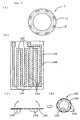
- FIG 1 shows an embodiment of a ceramic heater of the present invention.
- a ceramic heater 1 includes a cylindrical ceramic substrate 11 and a resistance heating element 12 which is embedded in the circumferential surface of the ceramic substrate 11.
- the ceramic substrate 11 includes a cylindrical core 2 and two ceramic layers 11a and 11b, which are situated on the outer circumferential surface of the core 2 in a layered form to thereby be integrated with the core 2.
- the resistance heating element 12 is disposed between the ceramic layers 11a and 11b.
- the resistance heating element 12 is formed in the following manner.
- a plurality of main body portions 4 extend in an axial direction of the ceramic substrate 11, are arranged at substantially equal intervals in the circumferential direction, and are sequentially connected to each other such that adjacent main body portions 4 are connected at both end portions by means of connection portions 5, thereby making a continuous zigzag form.
- Three lead portions 12a, 12b, and 12c for connection to a power source integrally extend from the rear end side of the resistance heating element 12 in the axial direction of the ceramic substrate 11 (the lead portion 12b is hidden).
- Terminal portions 9a, 9b, and 9c which are somewhat wider, are formed at end sections of the lead portions 12a, 12b, and 12c, respectively.
- the resistance heating element 12 is mainly composed of a metal having a high melting point, for example, W.
- the ceramic substrate 11 is mainly composed of A1203 and contains, as a sintering aid component, one or more of SiO2, MgO, CaO, B2O5, etc. in a total amount of not greater than 15% by weight.
- a dH/dB ratio is preferably adjusted to not greater than 0.8, more preferably not greater than 0.6.
- the average grain size dH for grains of the resistance heating element 12 is preferably 0.3 to 1.2 ⁇ m, more preferably 0.4 to 0.7 ⁇ m.
- the grains of the resistance heating element 12 are adjusted such that in a grain size distribution, a difference between the grain size d90%, which 90% of the grains are smaller than and a grain size d10%, which 10% of the grains are smaller than i.e., the difference of d90% - d10%, is not greater than 1.5 ⁇ m.
- the resistance heating element 12 is less susceptible to deteriorate even in the case of use at high temperature over a long period of time, thereby extending the service life of the ceramic heater 1. Also, when the ceramic heater 1 is manufactured through firing, the resistance heating element 12 is less susceptible to suffering a disconnection, a variation in resistance, or a like defect.
- the ceramic heater 1 can be manufactured, for example, in the following manner. As shown in Figure 2, a ceramic powder, together with a binder, is sheeted to obtain a powder compact 100b. Through use of a paste which contains a material powder for the resistance heater 12, a pattern 120 (including portions 104, which will become the main body portions 4, portions 105, which will become the connection portions 5, portions 112a, 112b, and 112c, which will become the lead portions 12a, 12b, and 12c, and portions 109a, 109b, and 109c, will become the terminals portions 9a, 9b, and 9c) of a resistance heating element is printed on a surface of the powder compact 100b.
- a pattern 120 including portions 104, which will become the main body portions 4, portions 105, which will become the connection portions 5, portions 112a, 112b, and 112c, which will become the lead portions 12a, 12b, and 12c, and portions 109a, 109b, and 109c, will become the terminals portions 9
- Terminal metal pieces (not shown) are arranged on the corresponding portions 109a, 109b, and 109c.
- another sheeted powder compact 100a is placed on the surface of the powder compact 100b on which the pattern 120 is formed, to thereby obtain a laminate.
- the laminate is wound onto the outer circumference of a cylindrical compact 102, which will serve as the core 2, followed by firing in a predetermined firing furnace.
- the compacts 100a, 100b, and 102 are united to become the ceramic substrate 11, and the printed pattern 120 becomes the resistance heating element 12, the lead portions 12a, 12b, and 12c, and the terminal portions 9a, 9b, and 9c.
- the ceramic heater 1 may be manufactured in the following manner. As shown in Figure 3(b), a pattern 120 of a resistance heating element is printed on a sheet surface of a powder compact 100. Next, as shown in Figure 3(c), the powder compact 100 is wound onto the outer circumferential surface of a separately formed cylindrical compact 102 such that the surface bearing the pattern 120 comes inside, thereby making a cylindrical compact 103 as shown in Figure 3(d). The thus-obtained compact 103 is fired, thereby obtaining a ceramic heater 1 shown in Figure 3(a).
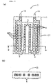
- FIG 4 shows an example of a sheet-shaped ceramic heater 1.
- the ceramic heater 1 includes a ceramic substrate (hereinafter, referred to merely as a substrate) 11 having a square (for example, rectangular) sheet shape and a resistance heating element 12 which is embedded in the substrate 11 at an intermediate portion in the thicknesswise direction. Portions used in common with the ceramic heater 1 of Figure 1 are denoted by common symbols, and their description is omitted.
- Numeral 8 denotes terminal metal pieces.
- the powder compacts 100a and 100b of Figure 2 were manufactured in the following manner. First, an A1203 powder (average grain size: 1.0 ⁇ m or 1.8 ⁇ m) and sintering aid components of SiO2 (average grain size: 1.4 ⁇ m), CaCO3 (average grain size: 3.2 ⁇ m; CaCO3 becomes CaO through firing), MgCO3 (average grain size: 4.1 ⁇ m; MgCO3 becomes MgO through firing), and Y203 were blended in predetermined amounts. The composition was adjusted such that a ceramic substrate after firing contains SiO2, CaO, MgO, and Y2O3 in a total amount of 4% to 15% by weight. To the resulting mixed powder were added a predetermined solvent and a predetermined binder.
- the resulting mixture was slurried through use of a ball mill.
- the thus-obtained slurry substance is defoamed under reduced pressure and sheeted into powder compacts 100a and 100b, each having a thickness 0.3 mm, through doctor blading.
- ink for printing the pattern 120 of a resistance heating element was prepared in the following manner.
- an Re powder average grain size: 1.5 ⁇ m
- an Al2O3 powder average grain size: 1.5 ⁇ m
- To the resulting mixture were added a solvent and a binder in predetermined amounts.
- the mixture was slurred through use of a ball mill. Subsequently, acetone was evaporated, obtaining an ink paste.
- the pattern 120 having a thickness of 25 ⁇ m was screenprinted on the surface of the powder compact 100b. Further, unillustrated terminal metal pieces were arranged in place, and the powder compact 100a was placed on the powder compact 100b. The thus-obtained laminate was wound onto the separately manufactured cylindrical compact 102 to obtain an unfired assembly. The assembly was subjected to a binder-removing process at 250°C and then fired at 1550°C for 1.5 hours in a hydrogen-containing atmosphere, thereby manufacturing various kinds of test products of the ceramic heater 1 shown in Figure 1 (200 test products were manufactured for each kind). The size of the ceramic heater 1 is adjusted to an outer diameter of 2.6 mm and a length of 60 mm, and the size of the resistance heating element 12 is adjusted such that the main body portion 4 has a width of 0.3 mm and a length of 20 mm.
- Some of the ceramic heaters 1 were cut. Cut surfaces were polished and observed through use of a scanning electron microscope (SEM). From SEM images a grain size distribution and a median (d50%; a grain size such that 50% of the grains are larger, and 50% of the grains are smaller; substantially equal to the average grain size dH) for component grains of the resistance heating element 12 and the average grain size dB for component grains of the ceramic substrate 11 were measured.
- a SEM image of a section of the ceramic substrate 11 was input into an analyzer. Through use of the analyzer, an area S of each grain appearing on the section was measured, and a diameter d of each grain was obtained through the calculation, 2 x (S/ ⁇ ) 1/2 (the diameter of a circle having the area S).
- a voltage of 24V was applied to the ceramic heaters 1 for up to 100 hours, thereby obtaining a percentage of the ceramic heaters 1 damaged by a disconnection or the like and a standard deviation of heater resistance. The results are shown in Table 1.
- the ceramic heaters 1 having a dH/dB of not greater than 0.8 exhibit a lower damage percentage with respect to the resistance heating element 12 and a smaller variation (standard deviation) in resistance of the resistance heating element 12 as compared to the ceramic heaters 1 having a dH/dB in excess of 0.8.
- the resistance heating element 12 becomes less susceptible to deterioration even in the case of use at high temperature over a long period of time, and the resistance heating element becomes less susceptible to suffering a disconnection, a variation in resistance, or a like defect during manufacture through firing.
- the ceramic heaters 1 in which the average grain size dH for component grains of the resistance heating element 12 falls within the 0.3 to 1.2 ⁇ m range exhibit a lower damage percentage with respect to the resistance heating element 12 and a smaller variation in resistance of the resistance heating element 12 as compared to the ceramic heaters 1 in which the average grain size dH falls outside the range.
Landscapes
- Engineering & Computer Science (AREA)
- Chemical & Material Sciences (AREA)
- Ceramic Engineering (AREA)
- Combustion & Propulsion (AREA)
- Mechanical Engineering (AREA)
- General Engineering & Computer Science (AREA)
- Inorganic Chemistry (AREA)
- Resistance Heating (AREA)
- Surface Heating Bodies (AREA)
Description
- The present invention relates to a ceramic heater, and more particularly to a ceramic heater for heating an oxygen sensor used with an automobile, for use in a glow system of a diesel engine, for heating a semiconductor substrate, for use in a fan heater, or the like.
- The above-mentioned ceramic heater is known to have a structure in which a resistance heating element formed from a metal having a high melting point such as W (tungsten) is embedded in a ceramic substrate formed into a flat shape, a cylindrical shape, or other shape. Such a ceramic heater is manufactured, for example, by the steps of: forming an unfired ceramic compact through sheet forming, extrusion, or a like process; forming a heating element pattern on the ceramic compact through use of paste which contains a high-melting-point metal powder and through thick-film printing or a like method; placing another ceramic compact thereon to obtain a layered assembly; and firing the assembly.
- Conventionally, when a ceramic heater of this kind is used continuously at a high temperature over a long period of time, the resistance heating element tends to deteriorate and suffer an increase in electric resistance, causing a shortening of service life of the heater. Such a deterioration in the resistance heating element is said to be caused by an electrochemical diffusion phenomenon, so-called electromigration (hereinafter, referred to merely as migration), in which a component of the resistance heating element or a component of the ceramic substrate electrochemically diffuses due to the application of current for the establishment of a high temperature (for example, in Japanese Patent Application Laid-Open No. 4-329291). For example, when a component of the resistance heating element diffuses into the ceramic substrate through migration, the resistance heating element is consumed at a portion from which the component has diffused out, and may suffer an excessive temperature rise or a disconnection. A metal oxide component, such as MgO or CaO, added as a sintering aid component is present in the form of glass phase within the ceramic substrate. Metal ions or oxygen ions contained in the glass phase also tend to migrate. For example, when the main component of the resistance heating element is W, the resistance heating element is oxidized by migrating oxygen ions and may suffer an increase in resistance, a disconnection, or a like problem.
- EP-A-0701979 is considered to comprise the closest prior art and forms the basis for the pre-characterizing portion of
claim 1. - In order to solve the above-mentioned problems, according to the invention there is provided a ceramic heater comprising a resistance heating element, said resistance heating element being mainly composed of a metal having a high melting point and being embedded in a ceramic substrate, wherein if the average grain size for grains of said ceramic substrate is termed dB and the average grain size of said resistance heating element is termed dH, the dH/dB ratio is not greater than 0.8.
- With the present invention the ceramic heater in which the resistance heating element is embedded is less likely to deteriorate even after continuous use at high temperature over a long period of time and which provides a long service life.
- The invention will be understood from the following description which is given by way of example only, with reference to the accompanying drawings in which:-
- Figure 1(a) is a partially cutaway perspective view showing an embodiment of a ceramic heater of the present invention;
- Figure 1(b) is a sectional view of a ceramic heater of the present invention taken along line A-A of Figure 1(a);
- Figure 2 is an exploded perspective view showing an example method for manufacturing the ceramic heater of Figure 1;
- Figure 3(a) is a sectional view showing a modification of the ceramic heater of the present invention;
- Figure 3(b) is a plan view of a first manufacturing step of the modification of the ceramic heater of the present invention;
- Figure 3(c) is a sectional view of a second manufacturing step of the modification of the ceramic heater of the present invention;
- Figure 3(d) is a sectional view of a third manufacturing step of the modification of the ceramic heater of the present invention;
- Figure 4(a) is a schematic view showing another modification of the ceramic heater of the present invention; and
- Figure 4(b) is a sectional view of the other modification of a ceramic heater of the present invention taken along line B-B of Figure 4(a).
-
- With an average grain size for grains of the ceramic substrate taken as dB and that for grains of the resistance heating element taken as dH, the dH/dB ratio is adjusted to be not greater than 0.8. Therefore, the resistance heating element is less likely to deteriorate even during use at high temperature over a long period of time, thereby realizing a ceramic heater having a long service life. Also, when the ceramic heater is manufactured through firing, the resistance heating element is less likely to suffer a disconnection, a variation in resistance or a like defect.
- A typical high-melting point metal usable in the present invention is W, but Mo is also usable. W and Mo may be used singly or in combination. The ceramic substrate may be mainly composed of Al2O3 for its excellent thermal conductivity, strength at high temperature, and corrosion resistance at high temperature. Also, a ceramic which contains an Al2O3 component, such as mullite, cordierite, or spinel may be used. The ceramic substrate may contain, as a sintering aid component, one or more of SiO2, MgO, CaO, B2O5, etc. in a total amount not greater than 15% by weight.
- When the dH/dB ratio is in excess of 0.8, the resistance heating element is apt to deteriorate during use at high temperature over a long period of time, causing a shortening of service life of the ceramic heater. When the ceramic heater is manufactured through firing, the resistance heating element has a high probability of suffering a disconnection, a variation in resistance, or a like defect. The dH/dB ratio is preferably adjusted to not greater than 0.7, more preferably not greater than 0.6.
- In the ceramic heater of the present invention, the high-temperature durability of the resistance heating element is enhanced. Also, when the ceramic heater is manufactured through firing, a defect is less likely to occur. Conceivable reasons for such features are as follows:
- (1) Through adjustment of the dH/dB ratio to not greater than 0.8, the size of the grains of the resistance heating element is set relatively small compared to that grains of the ceramic substrate. Accordingly, spaces are less likely to be formed among component grains of the resistance heating element. Even when such spaces are formed, they are finely dispersed. Thus, during sintering, a sintering aid component in a liquid glass phase is less likely to penetrate into spaces formed among component grains of the resistance heating element.
- (2) Employment of a relatively small grain size for component grains of the resistance heating element as described above means that grains of a material powder for the resistance heating element have a corresponding small size. During firing, grains of the material powder shrink, mainly because of a solid-phase sintering mechanism. In the solid-phase sintering mechanism, shrinkage is known to be more apt to progress as the grain size of powder decreases. Accordingly, through use of a material powder having a small grain size, firing promotes denseness (compactness) of the resistance heating element, whereby a glass phase is conceivably less likely to penetrate into the resistance heating element.
- (3) Through adjustment of the dH/dB ratio to not greater than 0.8, it is conceivable that a structure is formed in which, in an interface between the ceramic substrate and the resistance heating element, component grains of the resistance heating element are microscopically entangled in between component grains of the ceramic substrate. In this state, when the resistance heating element is compacted through firing, an associated shrinkage stress causes a liquid glass phase present between component grains in the vicinity of the interface of the component grains to be pushed back toward the ceramic substrate side, thereby enhancing the tendency to expel the glass phase from the vicinity of the interface.
-
- Presumably, because of at least one of these factors (1) through (3), an excessive glass phase is less likely to be formed in the interface between the ceramic substrate and the resistance heating element. As a result, migration is conceivably less likely to occur between the resistance heating element and the glass phase, thereby enhancing the high-temperature durability of the resistance heating element and suppressing the occurrence of defects during manufacture.
- When the dH/dB ratio is in excess of 0.8, the amount of the glass phase present in the vicinity of the interface increases; consequently, a bonding force of the ceramic substrate with the resistance heating element drops. When the ceramic heater in such a state is held at high temperature for a long period of time, the resistance heating element enters a state similar to floating in the fluidized glass phase, and consequently the state of fixing the resistance heating element onto the ceramic substrate becomes unstable. As a result, the resistance heating element becomes susceptible to a bending force and a local stress concentration induced by the ceramic substrate, as well as to suffering a disconnection and a like defect. However, in the ceramic heater of the present invention in which the dH/dB ratio is not greater than 0.8, by virtue of, for example, the above factor (3), a bonding force of the resistance heating element with the ceramic substrate is enhanced through firing compaction effected while the interface is in the entangled state described above. Additionally, the amount of the glass phase present in the vicinity of the interface decreases. Thus, even when the state of the fluidized glass phase continues for a long period of time, the resistance heating element can retain the state of being firmly fixed in the ceramic substrate. This is conceivably another reason for the ceramic heater of the present invention being enhanced in high-temperature durability and being less susceptible to the occurrence of a defect during manufacture thereof.
- Such an effect of the present invention is particularly notably achieved when the resistance heating is mainly composed of W and when the ceramic substrate is mainly composed of Al2O3.
- Preferably, an average grain size dH for grains of the resistance heating element is adjusted to 0.3 to 1.2 µm. When the dH value is in excess of 1.2 µm, the resistance heating element may deteriorate in the case of continuous high-temperature use over a long period of time or may suffer a disconnection, a variation in resistance, or a like defect during manufacture. This is conceivably because spaces are likely to be formed among grains of the resistance heating element, and thus the glass phase penetrates the resistance heating element from the ceramic substrate side, thereby increasing the potential for migration between the resistance heating element and the glass phase. When the dH value is less than 0.3 µm, a material powder for the resistance heating element mainly composed of a high-melting-point metal is apt to be oxidized, and thus handling of the powder becomes difficult during manufacture. Shrinkage of an oxidation-deteriorated powder becomes difficult to effect during firing, and thus there may arise problems such as a shortening of service life induced by deterioration in the resistance generating element and an increase in the probability of defect occurrence during manufacture. The dH value is preferably adjusted to 0.4 to 0.7 µm.
- Preferably, grains of the resistance heating element are adjusted such that, in a grain size distribution, a difference between the grain size d90%, which 90% of the grains are smaller than and the grain size d10%, which 10% of the grains are smaller than i.e., the difference d90% - d10%, is not greater than 1.5 µm. Through adjustment of the difference, d90% - d10%, to this range, the grain size distribution of component grains of the resistance heating element becomes narrow, thereby further suppressing deterioration of the resistance heating element in the case of high-temperature use over a long period of time and the occurrence of a defect during manufacture. When the difference, d90% - d10%, is in excess of 1.5 µm, shrinkage of the resistance heating element becomes difficult to effect during firing, so that migration tends to occur. As a result, the service life of the resistance heating element may be shortened or there may increase the probability of defect occurrence during manufacture and a variation in resistance among ceramic heaters. The difference, d90% - d10%, is preferably adjusted to not greater than 1.2 µm, more preferably not greater than 0.8 µm.
- Notably, one or more of high-melting-point metal components such as Re, Pt, or Rh may be added to the material for the resistance heating element in a predetermined amount (for example, not greater than 25% by weight with respect to a total amount of W and Mo). This improves the high-temperature corrosion resistance of the resistance heating element, thereby extending the service life of the ceramic heater. For example, when the resistance heating element is mainly composed of W, the effect of improving the corrosion resistance and high-temperature strength of the element becomes particularly notable through addition of Re. However, since Re, Pt, and Rh are all precious metals, their addition in excess of 25% by weight causes an increase in manufacturing cost for the resistance heating element, and further improvement in performance of the resistance heating element cannot be expected, and the performance of the resistance heating element may be even impaired.
- Next, a material for the resistance heating element may contain, in an amount of not greater than 25% by weight, ceramic whose main component is also used in the ceramic substrate. "Main component is also used in "means the type of ceramic component with the largest content is identical. Thus, the difference in coefficient of linear expansion between the resistance heating element and the ceramic substrate may be reduced, thereby suppressing damage to the resistance heating element which would otherwise result when heating and cooling are repeated, and suppressing a variation in resistance during manufacture. However, when the content is in excess of 25% by weight, the resistivity of the resistance heating element increases, causing a decrease in heat generation efficiency.
- Embodiments of the present invention will next be described with reference to drawings.
- Figure 1 shows an embodiment of a ceramic heater of the present invention. A
ceramic heater 1 includes a cylindricalceramic substrate 11 and aresistance heating element 12 which is embedded in the circumferential surface of theceramic substrate 11. Specifically, as shown in Figure 1(b), theceramic substrate 11 includes acylindrical core 2 and twoceramic layers 11a and 11b, which are situated on the outer circumferential surface of thecore 2 in a layered form to thereby be integrated with thecore 2. Theresistance heating element 12 is disposed between theceramic layers 11a and 11b. - As shown in Figure 1(a), the
resistance heating element 12 is formed in the following manner. A plurality ofmain body portions 4 extend in an axial direction of theceramic substrate 11, are arranged at substantially equal intervals in the circumferential direction, and are sequentially connected to each other such that adjacentmain body portions 4 are connected at both end portions by means ofconnection portions 5, thereby making a continuous zigzag form. Threelead portions resistance heating element 12 in the axial direction of the ceramic substrate 11 (thelead portion 12b is hidden). Terminal portions 9a, 9b, and 9c, which are somewhat wider, are formed at end sections of thelead portions - In the
ceramic heater 1, theresistance heating element 12 is mainly composed of a metal having a high melting point, for example, W. Theceramic substrate 11 is mainly composed of A1203 and contains, as a sintering aid component, one or more of SiO2, MgO, CaO, B2O5, etc. in a total amount of not greater than 15% by weight. With an average grain size for grains of theceramic substrate 11 taken as dB and that for grains of theresistance heating element 12 taken as dH, a dH/dB ratio is preferably adjusted to not greater than 0.8, more preferably not greater than 0.6. The average grain size dH for grains of theresistance heating element 12 is preferably 0.3 to 1.2 µm, more preferably 0.4 to 0.7 µm. Further, the grains of theresistance heating element 12 are adjusted such that in a grain size distribution, a difference between the grain size d90%, which 90% of the grains are smaller than and a grain size d10%, which 10% of the grains are smaller than i.e., the difference of d90% - d10%, is not greater than 1.5 µm. - In the
ceramic heater 1 having the above structure, theresistance heating element 12 is less susceptible to deteriorate even in the case of use at high temperature over a long period of time, thereby extending the service life of theceramic heater 1. Also, when theceramic heater 1 is manufactured through firing, theresistance heating element 12 is less susceptible to suffering a disconnection, a variation in resistance, or a like defect. - The
ceramic heater 1 can be manufactured, for example, in the following manner. As shown in Figure 2, a ceramic powder, together with a binder, is sheeted to obtain a powder compact 100b. Through use of a paste which contains a material powder for theresistance heater 12, a pattern 120 (includingportions 104, which will become themain body portions 4,portions 105, which will become theconnection portions 5,portions lead portions portions 109a, 109b, and 109c, will become the terminals portions 9a, 9b, and 9c) of a resistance heating element is printed on a surface of the powder compact 100b. Terminal metal pieces (not shown) are arranged on the correspondingportions 109a, 109b, and 109c. Next, another sheeted powder compact 100a is placed on the surface of the powder compact 100b on which thepattern 120 is formed, to thereby obtain a laminate. The laminate is wound onto the outer circumference of a cylindrical compact 102, which will serve as thecore 2, followed by firing in a predetermined firing furnace. Thus, thecompacts ceramic substrate 11, and the printedpattern 120 becomes theresistance heating element 12, thelead portions - Notably, the
ceramic heater 1 may be manufactured in the following manner. As shown in Figure 3(b), apattern 120 of a resistance heating element is printed on a sheet surface of apowder compact 100. Next, as shown in Figure 3(c), thepowder compact 100 is wound onto the outer circumferential surface of a separately formed cylindrical compact 102 such that the surface bearing thepattern 120 comes inside, thereby making a cylindrical compact 103 as shown in Figure 3(d). The thus-obtained compact 103 is fired, thereby obtaining aceramic heater 1 shown in Figure 3(a). - Figure 4 shows an example of a sheet-shaped
ceramic heater 1. Specifically, theceramic heater 1 includes a ceramic substrate (hereinafter, referred to merely as a substrate) 11 having a square (for example, rectangular) sheet shape and aresistance heating element 12 which is embedded in thesubstrate 11 at an intermediate portion in the thicknesswise direction. Portions used in common with theceramic heater 1 of Figure 1 are denoted by common symbols, and their description is omitted.Numeral 8 denotes terminal metal pieces. - Various kinds of the
ceramic heaters 1 shown in Figure 1 were manufactured. - The
powder compacts 100a and 100b of Figure 2 were manufactured in the following manner. First, an A1203 powder (average grain size: 1.0 µm or 1.8µm) and sintering aid components of SiO2 (average grain size: 1.4 µm), CaCO3 (average grain size: 3.2 µm; CaCO3 becomes CaO through firing), MgCO3 (average grain size: 4.1 µm; MgCO3 becomes MgO through firing), and Y203 were blended in predetermined amounts. The composition was adjusted such that a ceramic substrate after firing contains SiO2, CaO, MgO, and Y2O3 in a total amount of 4% to 15% by weight. To the resulting mixed powder were added a predetermined solvent and a predetermined binder. The resulting mixture was slurried through use of a ball mill. The thus-obtained slurry substance is defoamed under reduced pressure and sheeted intopowder compacts 100a and 100b, each having a thickness 0.3 mm, through doctor blading. - Next, ink for printing the
pattern 120 of a resistance heating element was prepared in the following manner. To each of W powders having various grain-size distributions was added, as needed, an Re powder (average grain size: 1.5 µm) or an Al2O3 powder (average grain size: 1.5 µm) in a predetermined amount. To the resulting mixture were added a solvent and a binder in predetermined amounts. The mixture was slurred through use of a ball mill. Subsequently, acetone was evaporated, obtaining an ink paste. - As shown in Figure 2, through use of the above ink, the
pattern 120 having a thickness of 25 µm was screenprinted on the surface of the powder compact 100b. Further, unillustrated terminal metal pieces were arranged in place, and the powder compact 100a was placed on the powder compact 100b. The thus-obtained laminate was wound onto the separately manufactured cylindrical compact 102 to obtain an unfired assembly. The assembly was subjected to a binder-removing process at 250°C and then fired at 1550°C for 1.5 hours in a hydrogen-containing atmosphere, thereby manufacturing various kinds of test products of theceramic heater 1 shown in Figure 1 (200 test products were manufactured for each kind). The size of theceramic heater 1 is adjusted to an outer diameter of 2.6 mm and a length of 60 mm, and the size of theresistance heating element 12 is adjusted such that themain body portion 4 has a width of 0.3 mm and a length of 20 mm. - Some of the
ceramic heaters 1 were cut. Cut surfaces were polished and observed through use of a scanning electron microscope (SEM). From SEM images a grain size distribution and a median (d50%; a grain size such that 50% of the grains are larger, and 50% of the grains are smaller; substantially equal to the average grain size dH) for component grains of theresistance heating element 12 and the average grain size dB for component grains of theceramic substrate 11 were measured. A SEM image of a section of theceramic substrate 11 was input into an analyzer. Through use of the analyzer, an area S of each grain appearing on the section was measured, and a diameter d of each grain was obtained through the calculation, 2 x (S/Π)1/2 (the diameter of a circle having the area S). A voltage of 24V was applied to theceramic heaters 1 for up to 100 hours, thereby obtaining a percentage of theceramic heaters 1 damaged by a disconnection or the like and a standard deviation of heater resistance. The results are shown in Table 1.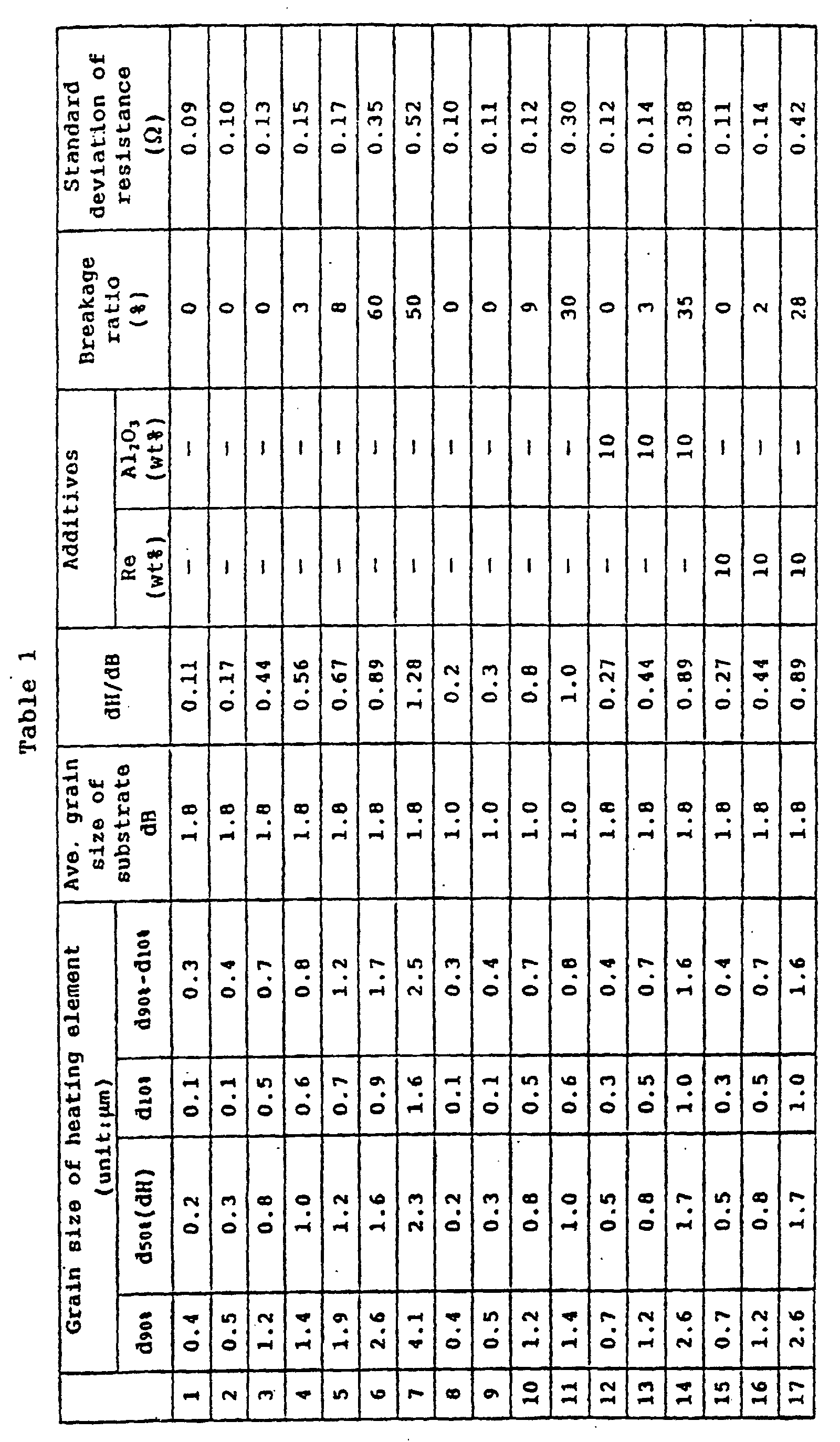
- As seen from the above results, the
ceramic heaters 1 having a dH/dB of not greater than 0.8 exhibit a lower damage percentage with respect to theresistance heating element 12 and a smaller variation (standard deviation) in resistance of theresistance heating element 12 as compared to theceramic heaters 1 having a dH/dB in excess of 0.8. In other words, through adjustment of the dH/dB ratio to not greater than 0.8, theresistance heating element 12 becomes less susceptible to deterioration even in the case of use at high temperature over a long period of time, and the resistance heating element becomes less susceptible to suffering a disconnection, a variation in resistance, or a like defect during manufacture through firing. - The
ceramic heaters 1 in which the average grain size dH for component grains of theresistance heating element 12 falls within the 0.3 to 1.2 µm range exhibit a lower damage percentage with respect to theresistance heating element 12 and a smaller variation in resistance of theresistance heating element 12 as compared to theceramic heaters 1 in which the average grain size dH falls outside the range. Further, theceramic heaters 1 in which a grain size distribution for component grains of theresistance heating element 12 is adjusted such that the difference, d90% - d10%, is not greater than 1.5 µm, exhibit a lower damage percentage with respect to theresistance heating element 12 and a smaller variation in resistance of theresistance heating element 12 as compared to theceramic heaters 1 in which the difference, d90% - d10%, is in excess of 1.5 µm. - The foregoing disclosure is the best mode devised by the inventors for practicing this invention. It is apparent, however, that devices incorporating modifications and variations will be obvious to one skilled in the art of ceramic heaters. Inasmuch as the foregoing disclosure presents the best mode contemplated by the inventors for carrying out the invention and is intended to enable any person skilled in the pertinent art to practice this invention, it should not be construed to be limited thereby but should be construed to include such aforementioned obvious variations and be limited only by the scope of the following claims.
Claims (10)
- A ceramic heater (1) comprising a resistance heating element (12), said resistance heating element (12) being mainly composed of a metal having a high melting point and being embedded in a ceramic substrate (11), characterized in that if the average grain size for grains of said ceramic substrate (11) is termed dB and the average grain size of said resistance heating element (12) is termed dH, the dH/dB ratio is not greater than 0.8.
- A ceramic heater according to claim 1, wherein the dH/dB ratio is not greater than 0.7.
- A ceramic heater according to claim 1, wherein the dH/dB ratio is not greater than 0.6
- A ceramic heater as described in Claim 1, 2 or 3, wherein the grains of said resistance heating element (12) are such that, the difference between a grain size d90%, i.e. the grain size which 90% of the grains are smaller than, and a grain size d10%, i.e. the grain size which 10% of the grains are smaller than, i.e. the difference d90% - d10%, is not greater than 1.5 µm.
- A ceramic heater according to claim 4, wherein the difference d90% - d10% is not greater than 1.2 µm.
- A ceramic heater according to claim 4, wherein the difference d90% - d10% is not greater than 0.8 µm.
- A ceramic heater as described in any one of the preceding claims, wherein the average grain size dH for grains of said resistance heating element (12) is in the range of 0.3 to 1.2 µm.
- A ceramic heater according to claim 7, wherein the average grain size dH for grains of said resistance heating element (12) is in the range 0.4 to 0.7 µm.
- A ceramic heater as described in any one of the preceding claims wherein material of said resistance heating element (12) contains Re in an amount of not greater than 25% by weight.
- A ceramic heater as described in any one of the preceding claims, wherein the material of said resistance heating element (12) contains, in an amount not greater than 25% by weight, ceramic whose main component is also used in said ceramic substrate.
Priority Applications (1)
| Application Number | Priority Date | Filing Date | Title |
|---|---|---|---|
| EP05001327.5A EP1524882A3 (en) | 1997-10-28 | 1998-10-27 | Ceramic heater |
Applications Claiming Priority (3)
| Application Number | Priority Date | Filing Date | Title |
|---|---|---|---|
| JP31269897 | 1997-10-28 | ||
| JP31269897A JP3691649B2 (en) | 1997-10-28 | 1997-10-28 | Ceramic heater |
| JP312698/97 | 1997-10-28 |
Related Child Applications (1)
| Application Number | Title | Priority Date | Filing Date |
|---|---|---|---|
| EP05001327.5A Division EP1524882A3 (en) | 1997-10-28 | 1998-10-27 | Ceramic heater |
Publications (3)
| Publication Number | Publication Date |
|---|---|
| EP0914021A2 EP0914021A2 (en) | 1999-05-06 |
| EP0914021A3 EP0914021A3 (en) | 2000-02-23 |
| EP0914021B1 true EP0914021B1 (en) | 2005-10-12 |
Family
ID=18032361
Family Applications (2)
| Application Number | Title | Priority Date | Filing Date |
|---|---|---|---|
| EP05001327.5A Withdrawn EP1524882A3 (en) | 1997-10-28 | 1998-10-27 | Ceramic heater |
| EP98308784A Expired - Lifetime EP0914021B1 (en) | 1997-10-28 | 1998-10-27 | Ceramic heater |
Family Applications Before (1)
| Application Number | Title | Priority Date | Filing Date |
|---|---|---|---|
| EP05001327.5A Withdrawn EP1524882A3 (en) | 1997-10-28 | 1998-10-27 | Ceramic heater |
Country Status (4)
| Country | Link |
|---|---|
| US (1) | US6084220A (en) |
| EP (2) | EP1524882A3 (en) |
| JP (1) | JP3691649B2 (en) |
| DE (1) | DE69831844T2 (en) |
Cited By (1)
| Publication number | Priority date | Publication date | Assignee | Title |
|---|---|---|---|---|
| EP2343950A1 (en) | 2010-01-11 | 2011-07-13 | HE System Electronic GmbH & Co. KG | Electrical heating element and method for its production |
Families Citing this family (33)
| Publication number | Priority date | Publication date | Assignee | Title |
|---|---|---|---|---|
| JP2000277240A (en) * | 1999-03-26 | 2000-10-06 | Ibiden Co Ltd | Ceramic heater |
| JP2000286045A (en) * | 1999-03-29 | 2000-10-13 | Ibiden Co Ltd | Ceramic heater |
| JP4028149B2 (en) * | 2000-02-03 | 2007-12-26 | 日本碍子株式会社 | Heating device |
| JP3921327B2 (en) * | 2000-04-14 | 2007-05-30 | 京セラ株式会社 | Ceramic heater and manufacturing method thereof |
| US7106167B2 (en) * | 2002-06-28 | 2006-09-12 | Heetronix | Stable high temperature sensor system with tungsten on AlN |
| KR20080108372A (en) * | 2003-12-24 | 2008-12-12 | 쿄세라 코포레이션 | Ceramic heater and its manufacturing method |
| JP4476701B2 (en) * | 2004-06-02 | 2010-06-09 | 日本碍子株式会社 | Manufacturing method of sintered body with built-in electrode |
| DE102004045383A1 (en) * | 2004-09-18 | 2006-03-23 | Robert Bosch Gmbh | Glow plug with combustion chamber pressure sensor |
| JP4826461B2 (en) * | 2006-12-15 | 2011-11-30 | 株式会社デンソー | Ceramic heater and gas sensor element using the same |
| EP2628355A1 (en) * | 2010-10-12 | 2013-08-21 | Mack Trucks, Inc. | Heated sensor element for mixed gas and liquid environments |
| JP5721846B2 (en) * | 2011-09-29 | 2015-05-20 | 京セラ株式会社 | Heater and glow plug equipped with the same |
| JP2013134880A (en) * | 2011-12-26 | 2013-07-08 | Valeo Japan Co Ltd | Ceramic heater and electric heating type hot water heating device using the same |
| US10480786B2 (en) * | 2012-06-29 | 2019-11-19 | Kyocera Corporation | Heater and glow plug including the same |
| GB2515992A (en) | 2013-03-22 | 2015-01-14 | British American Tobacco Co | Heating smokeable material |
| JP6406786B2 (en) * | 2013-11-06 | 2018-10-17 | 日本特殊陶業株式会社 | Gas sensor |
| FR3012872B1 (en) * | 2013-11-07 | 2015-11-13 | Valeo Systemes Thermiques | ELECTRIC FLUID HEAT CONDITIONING DEVICE FOR MOTOR VEHICLE, AND HEATING AND / OR AIR CONDITIONING APPARATUS THEREFOR |
| WO2015163483A1 (en) * | 2014-04-25 | 2015-10-29 | 京セラ株式会社 | Heater and ignition device |
| DE102014218638A1 (en) * | 2014-09-17 | 2016-03-31 | Siemens Aktiengesellschaft | Producing a component with a ceramic powder body |
| JP6604884B2 (en) * | 2016-03-30 | 2019-11-13 | 日本特殊陶業株式会社 | Ceramic heater |
| JP2017183218A (en) * | 2016-03-31 | 2017-10-05 | イビデン株式会社 | Manufacturing method of ceramic heater |
| GB201700136D0 (en) | 2017-01-05 | 2017-02-22 | British American Tobacco Investments Ltd | Aerosol generating device and article |
| GB201700620D0 (en) | 2017-01-13 | 2017-03-01 | British American Tobacco Investments Ltd | Aerosol generating device and article |
| WO2018199094A1 (en) * | 2017-04-26 | 2018-11-01 | 京セラ株式会社 | Heater |
| JP6792539B2 (en) * | 2017-10-31 | 2020-11-25 | 日本特殊陶業株式会社 | Ceramic heater for fluid heating |
| GB201720338D0 (en) | 2017-12-06 | 2018-01-17 | British American Tobacco Investments Ltd | Component for an aerosol-generating apparatus |
| CN207869432U (en) * | 2018-03-07 | 2018-09-14 | 东莞市国研电热材料有限公司 | A multi-temperature zone ceramic heating element |
| KR20200143691A (en) * | 2018-03-27 | 2020-12-24 | 에스씨피 홀딩스 언 어숨드 비지니스 네임 오브 나이트라이드 이그나이터스 엘엘씨 | High temperature surface igniter for cooktop |
| CN209090060U (en) * | 2018-09-21 | 2019-07-12 | 深圳市博迪科技开发有限公司 | A ceramic heating element and electronic cigarette |
| CN109526079B (en) * | 2018-12-18 | 2023-12-15 | 重庆利迈科技有限公司 | A kind of high voltage ceramic electric heating body |
| CN116868684A (en) * | 2021-04-08 | 2023-10-10 | 日本特殊陶业株式会社 | Ceramic heater and method for manufacturing ceramic heater |
| US20240125512A1 (en) * | 2021-05-18 | 2024-04-18 | Niterra Co., Ltd. | Ceramic heater and liquid heating device |
| JP7594492B2 (en) * | 2021-05-18 | 2024-12-04 | 日本特殊陶業株式会社 | Liquid Heating Device |
| CN118176826A (en) * | 2021-12-20 | 2024-06-11 | 日本特殊陶业株式会社 | Liquid heating device |
Family Cites Families (13)
| Publication number | Priority date | Publication date | Assignee | Title |
|---|---|---|---|---|
| US3694626A (en) * | 1971-09-30 | 1972-09-26 | Gen Electric | Electrical resistance heater |
| US3978183A (en) * | 1974-06-24 | 1976-08-31 | Sybron Corporation | Method of filter molding and electrical heating unit made thereby |
| DE2514578B2 (en) * | 1975-04-03 | 1978-09-07 | Fa. Fritz Eichenauer, 6744 Kandel | Refractory, granular investment material for electric heating coils |
| DE2825980A1 (en) * | 1978-06-14 | 1980-01-03 | Eichenauer Fa Fritz | ELECTRIC PIPE RADIATOR AND METHOD FOR THE PRODUCTION THEREOF |
| JPS59231321A (en) * | 1983-06-13 | 1984-12-26 | Ngk Spark Plug Co Ltd | Self-control type glow plug |
| JPS6029517A (en) * | 1983-07-29 | 1985-02-14 | Ngk Spark Plug Co Ltd | Ceramic glow plug |
| US4650963A (en) * | 1983-09-21 | 1987-03-17 | Ngk Spark Plug Co., Ltd. | Ceramic glow plug |
| JP2632347B2 (en) * | 1988-03-03 | 1997-07-23 | 日本特殊陶業株式会社 | Ceramic heater |
| JPH01313362A (en) * | 1988-06-09 | 1989-12-18 | Ngk Spark Plug Co Ltd | Ceramic heating element and production thereof |
| US5264681A (en) * | 1991-02-14 | 1993-11-23 | Ngk Spark Plug Co., Ltd. | Ceramic heater |
| JPH04329291A (en) * | 1991-05-02 | 1992-11-18 | Ngk Spark Plug Co Ltd | Ceramic hater and its manufacture |
| KR100361113B1 (en) * | 1994-08-18 | 2003-02-05 | 닛뽕도구슈우도오교오가부시끼가이샤 | Alumina-based sintered material for ceramic heater |
| JPH10300085A (en) * | 1997-04-22 | 1998-11-13 | Ngk Spark Plug Co Ltd | Ceramic heater and ceramic glow plug |
-
1997
- 1997-10-28 JP JP31269897A patent/JP3691649B2/en not_active Expired - Fee Related
-
1998
- 1998-10-22 US US09/177,648 patent/US6084220A/en not_active Expired - Lifetime
- 1998-10-27 DE DE69831844T patent/DE69831844T2/en not_active Expired - Lifetime
- 1998-10-27 EP EP05001327.5A patent/EP1524882A3/en not_active Withdrawn
- 1998-10-27 EP EP98308784A patent/EP0914021B1/en not_active Expired - Lifetime
Cited By (2)
| Publication number | Priority date | Publication date | Assignee | Title |
|---|---|---|---|---|
| EP2343950A1 (en) | 2010-01-11 | 2011-07-13 | HE System Electronic GmbH & Co. KG | Electrical heating element and method for its production |
| DE102010000042A1 (en) | 2010-01-11 | 2011-07-14 | HE System Electronic GmbH & Co. KG, 90587 | Electric heating element and a method for its production |
Also Published As
| Publication number | Publication date |
|---|---|
| EP1524882A3 (en) | 2014-04-02 |
| EP0914021A3 (en) | 2000-02-23 |
| US6084220A (en) | 2000-07-04 |
| JP3691649B2 (en) | 2005-09-07 |
| EP0914021A2 (en) | 1999-05-06 |
| DE69831844D1 (en) | 2006-02-23 |
| DE69831844T2 (en) | 2006-07-13 |
| JPH11135239A (en) | 1999-05-21 |
| EP1524882A2 (en) | 2005-04-20 |
Similar Documents
| Publication | Publication Date | Title |
|---|---|---|
| US6084220A (en) | Ceramic heater | |
| EP0963137B1 (en) | Ceramic heater and oxygen sensor using the same | |
| EP1768456B1 (en) | Ceramic heater, and glow plug using the same | |
| KR19980081629A (en) | Resistor spark plugs, resistor compositions for spark plugs, and methods for producing resistor spark plugs | |
| KR101127114B1 (en) | Ceramic heater and production method therefor and heating device and hair iron | |
| EP0948001A1 (en) | Resistance element | |
| JP3503761B2 (en) | Ceramic heater | |
| EP1734788B1 (en) | Ceramic-metal assembly and ceramic heater | |
| JP2004325196A (en) | Oxygen sensor element | |
| JP3929882B2 (en) | Flat ceramic heater and detection element using the same | |
| JPH08315967A (en) | Alumina ceramic heater with metallized heat generation layer | |
| JPH1025162A (en) | Ceramic sintered body | |
| JP4084593B2 (en) | Oxygen sensor element | |
| JP2001319757A (en) | Ceramic heater | |
| JP2005108690A (en) | Ceramic heater and ceramic heater structure | |
| JPH08506906A (en) | Insulating layer system for electrical isolation of current circuits | |
| JP3436769B2 (en) | Ceramic heater for oxygen sensor heating | |
| JP3813685B2 (en) | Ceramic heater | |
| JP2004342622A (en) | Ceramic heater | |
| JPH07106055A (en) | Quick temperature raising heating element and manufacture thereof | |
| JP3366546B2 (en) | Ceramic heater | |
| JP3898603B2 (en) | Oxygen sensor element | |
| JP3935059B2 (en) | Oxygen sensor element | |
| KR100413783B1 (en) | CERAMIC HEATER FOR HEATING SENSOR, INCLUDING HEATER SUBSTRATE PRODUCED BY ADDING MgO POWDER TO HIGH PURITY ALUMINA POWDER OF 99.999% OR HIGHER | |
| JP2002228622A (en) | Oxygen sensor and method of manufacturing the same |
Legal Events
| Date | Code | Title | Description |
|---|---|---|---|
| PUAI | Public reference made under article 153(3) epc to a published international application that has entered the european phase |
Free format text: ORIGINAL CODE: 0009012 |
|
| AK | Designated contracting states |
Kind code of ref document: A2 Designated state(s): DE FR GB IT |
|
| AX | Request for extension of the european patent |
Free format text: AL;LT;LV;MK;RO;SI |
|
| PUAL | Search report despatched |
Free format text: ORIGINAL CODE: 0009013 |
|
| AK | Designated contracting states |
Kind code of ref document: A3 Designated state(s): AT BE CH CY DE DK ES FI FR GB GR IE IT LI LU MC NL PT SE |
|
| AX | Request for extension of the european patent |
Free format text: AL;LT;LV;MK;RO;SI |
|
| RIC1 | Information provided on ipc code assigned before grant |
Free format text: 7H 05B 3/14 A, 7F 23Q 7/00 B, 7H 05B 3/28 B |
|
| 17P | Request for examination filed |
Effective date: 20000706 |
|
| AKX | Designation fees paid |
Free format text: DE FR GB IT |
|
| 17Q | First examination report despatched |
Effective date: 20040714 |
|
| GRAP | Despatch of communication of intention to grant a patent |
Free format text: ORIGINAL CODE: EPIDOSNIGR1 |
|
| GRAS | Grant fee paid |
Free format text: ORIGINAL CODE: EPIDOSNIGR3 |
|
| GRAA | (expected) grant |
Free format text: ORIGINAL CODE: 0009210 |
|
| AK | Designated contracting states |
Kind code of ref document: B1 Designated state(s): DE FR GB IT |
|
| PG25 | Lapsed in a contracting state [announced via postgrant information from national office to epo] |
Ref country code: IT Free format text: LAPSE BECAUSE OF FAILURE TO SUBMIT A TRANSLATION OF THE DESCRIPTION OR TO PAY THE FEE WITHIN THE PRE;WARNING: LAPSES OF ITALIAN PATENTS WITH EFFECTIVE DATE BEFORE 2007 MAY HAVE OCCURRED AT ANY TIME BEFORE 2007. THE CORRECT EFFECTIVE DATE MAY BE DIFFERENT FROM THE ONE RECORDED.SCRIBED TIME-LIMIT Effective date: 20051012 |
|
| REG | Reference to a national code |
Ref country code: GB Ref legal event code: FG4D |
|
| PG25 | Lapsed in a contracting state [announced via postgrant information from national office to epo] |
Ref country code: GB Free format text: LAPSE BECAUSE OF NON-PAYMENT OF DUE FEES Effective date: 20060112 |
|
| REF | Corresponds to: |
Ref document number: 69831844 Country of ref document: DE Date of ref document: 20060223 Kind code of ref document: P |
|
| PLBE | No opposition filed within time limit |
Free format text: ORIGINAL CODE: 0009261 |
|
| STAA | Information on the status of an ep patent application or granted ep patent |
Free format text: STATUS: NO OPPOSITION FILED WITHIN TIME LIMIT |
|
| 26N | No opposition filed |
Effective date: 20060713 |
|
| GBPC | Gb: european patent ceased through non-payment of renewal fee |
Effective date: 20060112 |
|
| PG25 | Lapsed in a contracting state [announced via postgrant information from national office to epo] |
Ref country code: FR Free format text: LAPSE BECAUSE OF FAILURE TO SUBMIT A TRANSLATION OF THE DESCRIPTION OR TO PAY THE FEE WITHIN THE PRESCRIBED TIME-LIMIT Effective date: 20061020 |
|
| EN | Fr: translation not filed | ||
| PG25 | Lapsed in a contracting state [announced via postgrant information from national office to epo] |
Ref country code: FR Free format text: LAPSE BECAUSE OF FAILURE TO SUBMIT A TRANSLATION OF THE DESCRIPTION OR TO PAY THE FEE WITHIN THE PRESCRIBED TIME-LIMIT Effective date: 20051031 |
|
| PG25 | Lapsed in a contracting state [announced via postgrant information from national office to epo] |
Ref country code: FR Free format text: LAPSE BECAUSE OF FAILURE TO SUBMIT A TRANSLATION OF THE DESCRIPTION OR TO PAY THE FEE WITHIN THE PRESCRIBED TIME-LIMIT Effective date: 20051012 |
|
| PGFP | Annual fee paid to national office [announced via postgrant information from national office to epo] |
Ref country code: DE Payment date: 20141023 Year of fee payment: 17 |
|
| REG | Reference to a national code |
Ref country code: DE Ref legal event code: R119 Ref document number: 69831844 Country of ref document: DE |
|
| PG25 | Lapsed in a contracting state [announced via postgrant information from national office to epo] |
Ref country code: DE Free format text: LAPSE BECAUSE OF NON-PAYMENT OF DUE FEES Effective date: 20160503 |