EP0912876B1 - Pedometer - Google Patents
Pedometer Download PDFInfo
- Publication number
- EP0912876B1 EP0912876B1 EP97929486A EP97929486A EP0912876B1 EP 0912876 B1 EP0912876 B1 EP 0912876B1 EP 97929486 A EP97929486 A EP 97929486A EP 97929486 A EP97929486 A EP 97929486A EP 0912876 B1 EP0912876 B1 EP 0912876B1
- Authority
- EP
- European Patent Office
- Prior art keywords
- signal
- running
- distance covered
- unit
- walking
- Prior art date
- Legal status (The legal status is an assumption and is not a legal conclusion. Google has not performed a legal analysis and makes no representation as to the accuracy of the status listed.)
- Expired - Lifetime
Links
- 230000000295 complement effect Effects 0.000 claims abstract description 4
- 210000002683 foot Anatomy 0.000 claims description 30
- 238000001514 detection method Methods 0.000 claims description 9
- 235000019577 caloric intake Nutrition 0.000 claims description 5
- 210000003423 ankle Anatomy 0.000 claims description 4
- 238000004364 calculation method Methods 0.000 claims description 4
- 239000004973 liquid crystal related substance Substances 0.000 claims description 4
- 239000000919 ceramic Substances 0.000 claims description 2
- 238000006243 chemical reaction Methods 0.000 claims description 2
- 239000013078 crystal Substances 0.000 claims description 2
- 238000000034 method Methods 0.000 abstract description 7
- 238000010586 diagram Methods 0.000 description 9
- 238000005259 measurement Methods 0.000 description 8
- XLYOFNOQVPJJNP-UHFFFAOYSA-N water Substances O XLYOFNOQVPJJNP-UHFFFAOYSA-N 0.000 description 3
- 244000025254 Cannabis sativa Species 0.000 description 1
- 230000005540 biological transmission Effects 0.000 description 1
- 238000010276 construction Methods 0.000 description 1
- 238000011156 evaluation Methods 0.000 description 1
- 230000006870 function Effects 0.000 description 1
- 230000000873 masking effect Effects 0.000 description 1
- 239000011150 reinforced concrete Substances 0.000 description 1
- 230000002787 reinforcement Effects 0.000 description 1
- 230000035939 shock Effects 0.000 description 1
- 230000001360 synchronised effect Effects 0.000 description 1
- 238000002604 ultrasonography Methods 0.000 description 1
- 238000004148 unit process Methods 0.000 description 1
Images


Classifications
-
- G—PHYSICS
- G01—MEASURING; TESTING
- G01C—MEASURING DISTANCES, LEVELS OR BEARINGS; SURVEYING; NAVIGATION; GYROSCOPIC INSTRUMENTS; PHOTOGRAMMETRY OR VIDEOGRAMMETRY
- G01C22/00—Measuring distance traversed on the ground by vehicles, persons, animals or other moving solid bodies, e.g. using odometers, using pedometers
- G01C22/006—Pedometers
-
- A—HUMAN NECESSITIES
- A43—FOOTWEAR
- A43B—CHARACTERISTIC FEATURES OF FOOTWEAR; PARTS OF FOOTWEAR
- A43B3/00—Footwear characterised by the shape or the use
-
- A—HUMAN NECESSITIES
- A43—FOOTWEAR
- A43B—CHARACTERISTIC FEATURES OF FOOTWEAR; PARTS OF FOOTWEAR
- A43B3/00—Footwear characterised by the shape or the use
- A43B3/34—Footwear characterised by the shape or the use with electrical or electronic arrangements
Definitions
- the present invention relates to the measurement of the distances covered and the speeds reached by walking and/or running people.
- system A) based on the use of ultrasounds has to be discarded both because of the fragility of the transducers which cannot withstand the mechanical stress in such an application and the difficulty of protecting them from water splashes (rain, puddles, etc.).
- System B) based on the use of radiofrequency signals has big application problems because it requires calibrations and is particularly sensitive to thermal variations. In order to overcome such problems it would be necessary to resort to a very expensive apparatus which would not be recommended for a commercial production.
- the drawback of system C) using a magnetic flow consists in that it is strongly depending on the type of pavement on which the user runs or walks causing high variations of parameters and characteristics of the detection system. To sum up, the method involving fewer problems of the measurement and display system is that of item D) above, i.e. that using an infrared transmitting/receiving system.
- the present invention seeks to overcome the problems mentioned above by providing a portable apparatus able to calculate with high precision the distance covered and the speed.
- the apparatus according to the invention essentially consists of two separate, complementary, electronic devices, one of which (slave) is able to transmit signals through suitable transmitting means, while the other (master) is able to receive said signals through suitable receiving means and to store and to process them so as to calculate the distance covered and the average and maximum speeds.
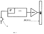
- FDM the measurement and display system
- the left foot at “lf” the right foot at “rf”
- the data display system at “display” the infrared ray at "I.R.”
- I.R the infrared ray at "I.R.”
- the construction and the design of FDM is made depend on that the mechanical stress, to which the apparatus is subjected, causes components requiring calibration such as resistive and capacitive trimmers as well as all of the components sensitive to mechanical shocks and vibrations to be avoided.
- sharp temperature variations can occur (e.g. when the foot accidentally ends up into a water puddle with lower temperature).
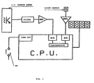
- the FDM consists of two complementary devices: "master” and “slave” supplied by cells and described below in their basic components.
- the master essentially includes:
- the slave essentially includes:
- Both units are provided with a self-switching on/off system so as to avoid any control by the user and at the same time to optimize the cell consumption.
- This is accomplished by two pressure sensors SP which enable the respective unit as soon as a change of state of the sensor occurs.
- the enabling condition of the units is kept until a change of state of the respective sensor SP is detected within a predetermined time-out. Therefore, as soon as the feet move both master and slave units begin their operations.
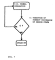
- any change of state of the relative pressure sensor SP causes the slave unit to leave the "sleep" state (stand-by with the minimum power consumption). At this time the time-out counting begins (fig.
- the first state takes place at the beginning of the movement when the feet are still and laid down.
- the second state takes place when the left foot is raised to start walking.
- sensor pressure SP changes its state and causes the slave unit to operate and to emit an infrared signal which is kept also when the foot is laid down again.
- the third state takes place after the end of the step of the left foot and the following raising of the right foot which causes the master unit to operate.
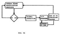
- the master unit operated by the change of state of pressure sensor SP detects the I.R. signal and stores a digit according to the amplitude of the latter.
- the master unit detects the signal at any change of state of its pressure sensor, i.e. both upon raising and laying down the right foot.
- the reverse succession takes place, i.e. the right foot is raised first, there are no problems because in this case the master unit is already operating when raising the left foot and then detects the modulated I.R. signal as soon as the slave unit starts the emission of the same.
- the master unit processes then the amplitude of the I.R.
- Such data are stored in the memory and can be increased by next movements or can be reset by a reset button.
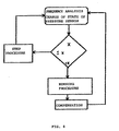
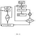
- the user In case the user is running, there is one more succession of states in the table shown above. Actually it should be considered the situation in which both feet are raised. Moreover, the feet can rotate backwards upon running with the result of a masking of the I.R. signal.
- the master unit is able to evaluate whether the user is walking or running (fig. 9) by only detecting the succession and the frequency of the changes of state of its pressure sensor. In such case, the signal measurement process is started in advance with respect to the time in which the right foot (where the master unit is installed) is laid down again. The amount of such a time in advance is proportional to the speed and can change every moment.
- the measurement is carried out before the foot rotates backwards. The same will take place before the foot is raised.
- the measurement of the signal is made in advance with respect to the time in which the right foot is raised from the ground.
- the time in advance in which the modulated I.R. signal is detected during the run is calculated by CPU according to the frequency of laying down/raising the foot to which the master unit is connected and depending on data stored in the memory and/or the program of CPU.
- a second embodiment of the invention further provides a calculation of the calories consumed by the user along a predetermined path.
- the master unit also provides a weight sensor such as a load cell able to evaluate the weight of the user.
- the CPU of the master unit calculates the calories employed during the walking and/or the run by comparing the detected weight, the distance covered, and the speed with its own data stored in the memory of the calculation program.
- Such beforehand obtained data e.g. during experimentations
Landscapes
- Engineering & Computer Science (AREA)
- General Physics & Mathematics (AREA)
- Radar, Positioning & Navigation (AREA)
- Remote Sensing (AREA)
- Microelectronics & Electronic Packaging (AREA)
- Physics & Mathematics (AREA)
- Photoreceptors In Electrophotography (AREA)
- Measuring Pulse, Heart Rate, Blood Pressure Or Blood Flow (AREA)
- Footwear And Its Accessory, Manufacturing Method And Apparatuses (AREA)
- Measurement Of Distances Traversed On The Ground (AREA)
- Length Measuring Devices With Unspecified Measuring Means (AREA)
- Optical Radar Systems And Details Thereof (AREA)
- Measurement Of The Respiration, Hearing Ability, Form, And Blood Characteristics Of Living Organisms (AREA)
- Rehabilitation Tools (AREA)
Claims (14)
- Vorrichtung zur Streckenmessung beim Gehen oder Laufen zum Einlegen in die Schuhe, gekennzeichnet durch zwei getrennte, komplementäre elektronische Geräte, die von Zellen gespeist werden, wobei eines dieser Geräte an einem von zwei Schuhen befestigt ist und über geeignete Sendevorrichtungen Signale erzeugen kann, während das andere Gerät an dem zweiten Schuh angebracht ist und diese Signale über geeignete Empfängervorrichtungen empfangen kann und diese für deren Umwandlung in einen Binärcode speichern und verarbeiten kann, wobei dieses andere Gerät dabei auch die vom Läufer bzw. Fußgänger zurückgelegte Strecke zusammen mit den Durchschnitts- und Höchstgeschwindigkeiten berechnen und diese Werte sofort anzeigen kann, wobei die Signale moduliert und richtungsabhängig sind, so dass der Umfang, in dem sie vom Master-Gerät empfangen werden, proportional zu der Entfernung zwischen der Sende- und der Empfängervorrichtung ist, wobei des weiteren eine Vorrichtung zur Anzeige der verarbeiteten Daten vorgesehen ist.
- Vorrichtung nach Anspruch 1, dadurch gekennzeichnet, dass die an dem einen Schuh befestigte Sendeeinheit und die an dem anderen Schuh befestigte Empfängereinheit mit automatischen Selbstschaltvorrichtungen mit Logik-Bausteinen (CPU) versehen sind, welche bei Eintreten einer Zustandsänderung der Sensoren von Ad Hoc-Drucksensoren (SP) aktiviert werden, die diesen zugeordnet sind, wobei dieser Einschaltzustand für eine vorbestimmte Zeitdauer beibehalten wird, nach der sich die Einheiten wiederum automatisch abschalten, um jedwede Steuerung durch den Benutzer zu verhindern und gleichzeitig den Stromverbrauch der Versorgungszellen zu minimieren.
- Vorrichtung zur Streckenmessung beim Gehen oder Laufen nach Anspruch 1, dadurch gekennzeichnet, dass Vorrichtungen zur Umwandlung des Signals nach dessen Empfang durch das Master-Gerät in ein digitales Signal und zum Vergleich des Signals mit einer Bezugsspannung vorgesehen sind, woraus sich eine binäre Zahl zwischen 0 und 255 ergibt, die dann in einem Register abgelegt wird, wobei diese Zahl im Register zu den zuvor darin gespeicherten Werten hinzuaddiert wird, bis das Register voll ist, und weitere Register zum Laden der nachfolgenden binären Zahlen vorgesehen sind, wobei die Daten bezüglich der zurückgelegten Gesamtstrecke und der Durchschnitts- und Höchstgeschwindigkeit unmittelbar nach dem Zurückschalten der Empfängereinheit in den Standby-Modus angezeigt werden, d.h. genau dann, wenn der Läufer zu laufen bzw. gehen aufhört.
- Vorrichtung zur Streckenmessung beim Gehen oder Laufen gemäß Anspruch 1 und 2, dadurch gekennzeichnet, dass die Register in ansteigender Reihenfolge angeordnet sind und Einheiten, Zehner, Hunderter und Tausender, darstellen.
- Vorrichtung nach einem der voranstehenden Ansprüche, dadurch gekennzeichnet, dass es sich bei den richtungsabhängigen Signalen um modulierte Infrarotstrahlen handelt.
- Vorrichtung nach einem der voranstehenden Ansprüche, dadurch gekennzeichnet, dass es sich bei den Sendevorrichtungen um Leuchtdioden zur Infrarotübertragung und bei den Empfängervorrichtungen um Empfänger-Photodioden handelt.
- Vorrichtung nach einem der voranstehenden Ansprüche, dadurch gekennzeichnet, dass die Sendeeinheit im wesentlichen aus folgendem besteht:und dadurch, dass die Empfängereinheit im wesentlichen aus folgendem besteht:einem Impulsgenerator, der Impulssignale an infrarotabstrahlende Leuchtdioden überträgt;einem Pufferstromverstärker zur Steuerung der infrarotabstrahlenden Leuchtdioden;einer Anordnung von infrarotabstrahlenden Leuchtdioden, die vorzugsweise in einem Gehäuse halbkreisförmig um die Innenseite des linken Fußgelenks herum verlaufend angeordnet sind;einem Drucksensor (SP), der zur Aktivierung bzw. Deaktivierung der Abstrahlung von Infrarotstrahlen in der Lage ist;einem Logikbaustein (CPU) zur Steuerung des Betriebs der Vorrichtung;einem Logikbaustein in Form eines Mikrocomputers, der mathematische Berechnungen durchführen kann und zur Steuerung einer Anzeige ausgelegt ist;einer Flüssigkristallanzeige zur Anzeige von Daten bezüglich der zurückgelegten Strecke, der Durchschnittsgeschwindigkeit, der Höchstgeschwindigkeit, etc.;einem Drucksensor (SP) zur Erfassung der effektiven Bewegung des rechten Fußes, der die Erfassung des Signals synchronisieren und die Vorrichtung automatisch ein- bzw. ausschalten kann;einer Anordnung von Sensoren (Infrarotempfänger), die in einem sonnenlichtundurchlässigen Gehäuse halbkreisförmig um die Innenseite des rechten Fußgelenks herum verlaufend angeordnet ist;einem Filter, der das am Ausgang der Infrarotsensoren modulierte Infrarotsignal auswählt;einem Signalverstärker, dessen Verstärkung derart gewählt ist, dass der Höchstwert des verstärkten Signals stets kleiner oder gleich dem von der die CPU zugelassenen Höchstwert ist, um den Analog/Digital-Wandler nicht zu sättigen und Erfassungsfehler zu vermeiden;einem Außenlichtsensor zur automatischen Kompensation des Signals zu unterschiedlichen Tageszeiten oder im Fall des plötzlichen Durchquerens dunkler Orte.
- Vorrichtung nach Anspruch 7, dadurch gekennzeichnet, dass der Logikbaustein (CPU) der Empfängereinheit folgende charakteristische Merkmale aufweist: einen ausreichend breiten Betriebstemperaturbereich; eine äußerst niedrige Speisespannung (2-3 V); äußerst geringen Stromverbrauch im Standby-Modus (in der Größenordnung von Bruchteilen eines Mikroamperes); eine Schnittstelle, die eine Flüssigkristallanzeige steuert und mit einem Rechteckwellengenerator versehen ist; einen Analog/Digital-Wandler zum Messen der Signalamplitude; eine Auflösung von mindestens 8 Bit; einen temperaturstabilen Bezugsspannungsgenerator; einen keramischen Resonator-Oszillator (robuster als ein Kristalloszillator), dessen Frequenz so nahe wie möglich an der höchstzulässigen Frequenz von Mikrocomputer und Resonator liegt.
- Vorrichtung nach Anspruch 7, dadurch gekennzeichnet, dass der Verstärker eine gute Wärmestabilität sowie äußerst niedrigen Stromverbrauch (CMOS) hat.
- Vorrichtung nach einem der Ansprüche 7-9, dadurch gekennzeichnet, dass der Logikbaustein des Master-Geräts anhand von Daten, die der Drucksensor erfasst, unterscheiden kann, ob der Benutzer gerade geht oder läuft, und im Fall des Laufens des Benutzers die Erfassung der von den Photodioden empfangenen Signale sowohl bezüglich der Zeit des Ablegens des Fußes als auch der Zeit des Anhebens des Fußes im voraus begonnen wird.
- Vorrichtung nach Anspruch 10, dadurch gekennzeichnet, dass der Logikbaustein (CPU) der Empfängereinheit oder Master-Einheit die Menge einer solchen Zeit im voraus durch Vergleich der erfassten Daten mit den in seinem Steuerprogramm gespeicherten Daten berechnet.
- Vorrichtung nach einem der voranstehenden Ansprüche, dadurch gekennzeichnet, dass die Empfängereinheit des weiteren einen Gewichtssensor enthält, beispielsweise eine Lastzelle, der das Gewicht des Benutzers auswerten kann, wobei deren Logikbaustein auch ein Programm zur Berechnung des Kalorienverbrauchs auf der Grundlage von Gewicht, zurückgelegter Strecke und Geschwindigkeit enthält.
- Vorrichtung nach Anspruch 12, dadurch gekennzeichnet, dass die Berechnung des Kalorienverbrauchs durch Vergleich der erfassten Daten mit den im Berechnungsprogramm gespeicherten erfolgt.
- Vorrichtung nach Anspruch 13, dadurch gekennzeichnet, dass das Berechnungsprogramm einen Dateninterpolationsalgorithmus umfasst, der in der Lage ist, die Menge gespeicherter Daten und somit auch den Speicherbedarf im Logikbaustein zu verringern.
Applications Claiming Priority (3)
| Application Number | Priority Date | Filing Date | Title |
|---|---|---|---|
| IT96RM000464A IT1284186B1 (it) | 1996-06-28 | 1996-06-28 | Dispositivo di misurazione della distanza percorsa a piedi (camminando o correndo) , applicabile all'interno di calzature o di |
| ITRM960464 | 1996-06-28 | ||
| PCT/IT1997/000151 WO1998000683A1 (en) | 1996-06-28 | 1997-06-26 | Pedometer |
Publications (2)
| Publication Number | Publication Date |
|---|---|
| EP0912876A1 EP0912876A1 (de) | 1999-05-06 |
| EP0912876B1 true EP0912876B1 (de) | 2002-11-20 |
Family
ID=11404315
Family Applications (1)
| Application Number | Title | Priority Date | Filing Date |
|---|---|---|---|
| EP97929486A Expired - Lifetime EP0912876B1 (de) | 1996-06-28 | 1997-06-26 | Pedometer |
Country Status (9)
| Country | Link |
|---|---|
| US (1) | US6243659B1 (de) |
| EP (1) | EP0912876B1 (de) |
| JP (1) | JP2000513448A (de) |
| AT (1) | ATE228238T1 (de) |
| AU (1) | AU3357797A (de) |
| CA (1) | CA2257520A1 (de) |
| DE (1) | DE69717278T2 (de) |
| IT (1) | IT1284186B1 (de) |
| WO (1) | WO1998000683A1 (de) |
Families Citing this family (15)
| Publication number | Priority date | Publication date | Assignee | Title |
|---|---|---|---|---|
| US6805006B2 (en) * | 2000-12-07 | 2004-10-19 | Bbc International, Ltd. | Method and apparatus for measuring the maximum speed of a runner over a prescribed distance including a transmitter and receiver |
| US6738726B2 (en) * | 2000-12-07 | 2004-05-18 | Bbc International, Ltd. | Apparatus and method for measuring the maximum speed of a runner over a prescribed distance |
| US6658079B1 (en) * | 2002-07-29 | 2003-12-02 | Hewlett-Packard Development Company, L.P. | System, method and apparatus for measuring walking and running distance |
| JP2005267152A (ja) * | 2004-03-18 | 2005-09-29 | Seiko Instruments Inc | 電子歩数計 |
| GR1005785B (el) * | 2005-05-19 | 2008-01-29 | Βασιλικη-Ειρηνη Στραπατσακη | Συσκευη μετρησης διανυομενων αποστασεων απο δρομεα |
| JP4830789B2 (ja) * | 2006-10-30 | 2011-12-07 | オムロンヘルスケア株式会社 | 体動検出装置、情報送信装置、ノルディックウォーキング用ストック、および歩行運動量算出システム |
| WO2008101085A2 (en) | 2007-02-14 | 2008-08-21 | Nike, Inc. | Collection and display of athletic information |
| US8253586B1 (en) | 2009-04-24 | 2012-08-28 | Mayfonk Art, Inc. | Athletic-wear having integral measuring sensors |
| US9855484B1 (en) | 2009-04-24 | 2018-01-02 | Mayfonk Athletic, Llc | Systems, methods, and apparatus for measuring athletic performance characteristics |
| US8990045B2 (en) * | 2009-11-18 | 2015-03-24 | Silicon Valley Micro E Corp. | Pedometer with shoe mounted sensor and transmitter |
| EP2458338B1 (de) * | 2010-11-25 | 2014-12-31 | Silicon Valley Micro E Corporation | Schrittzähler mit am Schuh montierten Sensor und Sender |
| TWI495849B (zh) * | 2010-11-25 | 2015-08-11 | Silicon Valley Micro E Corp | 安裝感測器與傳送器之鞋的計步器 |
| CN102564448B (zh) * | 2010-12-10 | 2016-06-08 | 硅谷微E股份有限公司 | 具有鞋装传感器和发射机的计步器 |
| CN109282806B (zh) * | 2017-07-20 | 2024-03-22 | 罗伯特·博世有限公司 | 用于确定步行者位置的方法、装置和存储介质 |
| FR3072251B1 (fr) * | 2017-10-16 | 2021-02-26 | Zhor Tech | Dispositif electronique pour produits chaussants. |
Family Cites Families (10)
| Publication number | Priority date | Publication date | Assignee | Title |
|---|---|---|---|---|
| JPS57151807A (en) | 1981-03-16 | 1982-09-20 | Secoh Giken Inc | Distance measuring device |
| US4578769A (en) * | 1983-02-09 | 1986-03-25 | Nike, Inc. | Device for determining the speed, distance traversed, elapsed time and calories expended by a person while running |
| DE3405081A1 (de) * | 1984-02-13 | 1985-08-14 | Puma-Sportschuhfabriken Rudolf Dassler Kg, 8522 Herzogenaurach | Sportschuh fuer laufdisziplinen und verfahren zur informationsabgabe und/oder zum informationsaustausch ueber bewegungsablaeufe bei laufdisziplinen |
| DE3505521A1 (de) * | 1985-02-18 | 1986-08-21 | Puma-Sportschuhfabriken Rudolf Dassler Kg, 8522 Herzogenaurach | Anlage zur ermittlung der bewegungsablaeufe bei laufdisziplinen |
| DE3514130A1 (de) | 1985-04-19 | 1985-11-07 | Klaus-Dieter 7060 Schorndorf Hufenbach | Geh-, lauf- und bewegungsmesser, welcher mit hilfe von strahlen, schwingungen oder wellen die geschwindigkeiten, rhythmen und zeitablaeufe misst |
| US5033013A (en) * | 1985-04-22 | 1991-07-16 | Yamasa Tokei Meter Co., Ltd. | Method and apparatus for measuring the amount of exercise |
| US4741001A (en) * | 1986-05-02 | 1988-04-26 | Robert Ma | Pedometer stop watch |
| US5117444A (en) * | 1990-07-30 | 1992-05-26 | W. Ron Sutton | High accuracy pedometer and calibration method |
| US5724265A (en) * | 1995-12-12 | 1998-03-03 | Hutchings; Lawrence J. | System and method for measuring movement of objects |
| US6073086A (en) * | 1998-01-14 | 2000-06-06 | Silicon Pie, Inc. | Time of motion, speed, and trajectory height measuring device |
-
1996
- 1996-06-28 IT IT96RM000464A patent/IT1284186B1/it active IP Right Grant
-
1997
- 1997-06-26 US US09/202,334 patent/US6243659B1/en not_active Expired - Fee Related
- 1997-06-26 EP EP97929486A patent/EP0912876B1/de not_active Expired - Lifetime
- 1997-06-26 JP JP10503972A patent/JP2000513448A/ja not_active Ceased
- 1997-06-26 AU AU33577/97A patent/AU3357797A/en not_active Abandoned
- 1997-06-26 CA CA002257520A patent/CA2257520A1/en not_active Abandoned
- 1997-06-26 AT AT97929486T patent/ATE228238T1/de not_active IP Right Cessation
- 1997-06-26 WO PCT/IT1997/000151 patent/WO1998000683A1/en not_active Ceased
- 1997-06-26 DE DE69717278T patent/DE69717278T2/de not_active Expired - Fee Related
Also Published As
| Publication number | Publication date |
|---|---|
| JP2000513448A (ja) | 2000-10-10 |
| ITRM960464A0 (de) | 1996-06-28 |
| ITRM960464A1 (it) | 1997-12-28 |
| DE69717278D1 (en) | 2003-01-02 |
| US6243659B1 (en) | 2001-06-05 |
| HK1019786A1 (en) | 2000-02-25 |
| WO1998000683A1 (en) | 1998-01-08 |
| AU3357797A (en) | 1998-01-21 |
| CA2257520A1 (en) | 1998-01-08 |
| ATE228238T1 (de) | 2002-12-15 |
| DE69717278T2 (de) | 2003-07-24 |
| IT1284186B1 (it) | 1998-05-08 |
| EP0912876A1 (de) | 1999-05-06 |
Similar Documents
| Publication | Publication Date | Title |
|---|---|---|
| EP0912876B1 (de) | Pedometer | |
| US6014100A (en) | Two-wire RADAR sensor with intermittently operating circuitry components | |
| US7791715B1 (en) | Method and system for lossless dealiasing in time-of-flight (TOF) systems | |
| US8629976B2 (en) | Methods and systems for hierarchical de-aliasing time-of-flight (TOF) systems | |
| US4763287A (en) | Measuring performance information in running disciplines and shoe systems | |
| US6741343B2 (en) | Level with angle and distance measurement apparatus | |
| EP0721595B1 (de) | Lasersensor, mit der möglichkeit der messung von entfernung, geschwindigkeit und beschleunigung | |
| US6658079B1 (en) | System, method and apparatus for measuring walking and running distance | |
| US20080015811A1 (en) | Handheld laser light detector with height correction, using a GPS receiver to provide two-dimensional position data | |
| US6708570B2 (en) | Flow rate measurement method, ultrasonic flow rate meter, flow velocity measurement method, temperature or pressure measurement method, ultrasonic thermometer and ultrasonic pressure gage | |
| KR910008387A (ko) | 측정 시스템 | |
| JPS6457112A (en) | Portable measuring apparatus | |
| US4107684A (en) | Phase locked detector | |
| JP2000509485A (ja) | 対象物の位置検出方法 | |
| HK1019786B (en) | Pedometer | |
| KR101156848B1 (ko) | 신발에 내장된 운동량 확인 및 위치 추적 장치 | |
| JP2011112360A (ja) | 歩行データ計測装置 | |
| JP2000352529A (ja) | 地滑り等の警報装置 | |
| JP2003194915A (ja) | 測位装置および測位システム | |
| JP3825580B2 (ja) | 携帯型距離・速度計 | |
| CN218566499U (zh) | 基于灰度传感的数字水准仪装置 | |
| JPS6253046B2 (de) | ||
| WO2000068642A2 (en) | Apparatus for determining the speed of travel and distance travelled by a user | |
| JPS55147379A (en) | Method of forecasting freezing of road surface | |
| JP2002296344A (ja) | 距離測定装置 |
Legal Events
| Date | Code | Title | Description |
|---|---|---|---|
| PUAI | Public reference made under article 153(3) epc to a published international application that has entered the european phase |
Free format text: ORIGINAL CODE: 0009012 |
|
| 17P | Request for examination filed |
Effective date: 19990127 |
|
| AK | Designated contracting states |
Kind code of ref document: A1 Designated state(s): AT BE CH DE DK ES FI FR GB GR IE IT LI LU MC NL PT SE |
|
| 17Q | First examination report despatched |
Effective date: 20010706 |
|
| GRAG | Despatch of communication of intention to grant |
Free format text: ORIGINAL CODE: EPIDOS AGRA |
|
| GRAG | Despatch of communication of intention to grant |
Free format text: ORIGINAL CODE: EPIDOS AGRA |
|
| GRAH | Despatch of communication of intention to grant a patent |
Free format text: ORIGINAL CODE: EPIDOS IGRA |
|
| GRAH | Despatch of communication of intention to grant a patent |
Free format text: ORIGINAL CODE: EPIDOS IGRA |
|
| GRAA | (expected) grant |
Free format text: ORIGINAL CODE: 0009210 |
|
| AK | Designated contracting states |
Kind code of ref document: B1 Designated state(s): AT BE CH DE DK ES FI FR GB GR IE IT LI LU MC NL PT SE |
|
| PG25 | Lapsed in a contracting state [announced via postgrant information from national office to epo] |
Ref country code: NL Free format text: LAPSE BECAUSE OF FAILURE TO SUBMIT A TRANSLATION OF THE DESCRIPTION OR TO PAY THE FEE WITHIN THE PRESCRIBED TIME-LIMIT Effective date: 20021120 Ref country code: LI Free format text: LAPSE BECAUSE OF FAILURE TO SUBMIT A TRANSLATION OF THE DESCRIPTION OR TO PAY THE FEE WITHIN THE PRESCRIBED TIME-LIMIT Effective date: 20021120 Ref country code: GR Free format text: LAPSE BECAUSE OF FAILURE TO SUBMIT A TRANSLATION OF THE DESCRIPTION OR TO PAY THE FEE WITHIN THE PRESCRIBED TIME-LIMIT Effective date: 20021120 Ref country code: FI Free format text: LAPSE BECAUSE OF FAILURE TO SUBMIT A TRANSLATION OF THE DESCRIPTION OR TO PAY THE FEE WITHIN THE PRESCRIBED TIME-LIMIT Effective date: 20021120 Ref country code: CH Free format text: LAPSE BECAUSE OF FAILURE TO SUBMIT A TRANSLATION OF THE DESCRIPTION OR TO PAY THE FEE WITHIN THE PRESCRIBED TIME-LIMIT Effective date: 20021120 Ref country code: BE Free format text: LAPSE BECAUSE OF FAILURE TO SUBMIT A TRANSLATION OF THE DESCRIPTION OR TO PAY THE FEE WITHIN THE PRESCRIBED TIME-LIMIT Effective date: 20021120 Ref country code: AT Free format text: LAPSE BECAUSE OF FAILURE TO SUBMIT A TRANSLATION OF THE DESCRIPTION OR TO PAY THE FEE WITHIN THE PRESCRIBED TIME-LIMIT Effective date: 20021120 |
|
| REF | Corresponds to: |
Ref document number: 228238 Country of ref document: AT Date of ref document: 20021215 Kind code of ref document: T |
|
| REG | Reference to a national code |
Ref country code: GB Ref legal event code: FG4D |
|
| REG | Reference to a national code |
Ref country code: CH Ref legal event code: EP |
|
| REG | Reference to a national code |
Ref country code: IE Ref legal event code: FG4D |
|
| REF | Corresponds to: |
Ref document number: 69717278 Country of ref document: DE Date of ref document: 20030102 |
|
| PG25 | Lapsed in a contracting state [announced via postgrant information from national office to epo] |
Ref country code: SE Free format text: LAPSE BECAUSE OF FAILURE TO SUBMIT A TRANSLATION OF THE DESCRIPTION OR TO PAY THE FEE WITHIN THE PRESCRIBED TIME-LIMIT Effective date: 20030220 Ref country code: PT Free format text: LAPSE BECAUSE OF FAILURE TO SUBMIT A TRANSLATION OF THE DESCRIPTION OR TO PAY THE FEE WITHIN THE PRESCRIBED TIME-LIMIT Effective date: 20030220 Ref country code: DK Free format text: LAPSE BECAUSE OF FAILURE TO SUBMIT A TRANSLATION OF THE DESCRIPTION OR TO PAY THE FEE WITHIN THE PRESCRIBED TIME-LIMIT Effective date: 20030220 |
|
| NLV1 | Nl: lapsed or annulled due to failure to fulfill the requirements of art. 29p and 29m of the patents act | ||
| PG25 | Lapsed in a contracting state [announced via postgrant information from national office to epo] |
Ref country code: ES Free format text: LAPSE BECAUSE OF FAILURE TO SUBMIT A TRANSLATION OF THE DESCRIPTION OR TO PAY THE FEE WITHIN THE PRESCRIBED TIME-LIMIT Effective date: 20030529 |
|
| REG | Reference to a national code |
Ref country code: CH Ref legal event code: PL |
|
| PG25 | Lapsed in a contracting state [announced via postgrant information from national office to epo] |
Ref country code: LU Free format text: LAPSE BECAUSE OF NON-PAYMENT OF DUE FEES Effective date: 20030626 Ref country code: IE Free format text: LAPSE BECAUSE OF NON-PAYMENT OF DUE FEES Effective date: 20030626 |
|
| PG25 | Lapsed in a contracting state [announced via postgrant information from national office to epo] |
Ref country code: MC Free format text: LAPSE BECAUSE OF NON-PAYMENT OF DUE FEES Effective date: 20030630 |
|
| ET | Fr: translation filed | ||
| PLBE | No opposition filed within time limit |
Free format text: ORIGINAL CODE: 0009261 |
|
| STAA | Information on the status of an ep patent application or granted ep patent |
Free format text: STATUS: NO OPPOSITION FILED WITHIN TIME LIMIT |
|
| 26N | No opposition filed |
Effective date: 20030821 |
|
| REG | Reference to a national code |
Ref country code: IE Ref legal event code: MM4A |
|
| PGFP | Annual fee paid to national office [announced via postgrant information from national office to epo] |
Ref country code: GB Payment date: 20050620 Year of fee payment: 9 |
|
| PGFP | Annual fee paid to national office [announced via postgrant information from national office to epo] |
Ref country code: FR Payment date: 20050630 Year of fee payment: 9 Ref country code: DE Payment date: 20050630 Year of fee payment: 9 |
|
| PG25 | Lapsed in a contracting state [announced via postgrant information from national office to epo] |
Ref country code: GB Free format text: LAPSE BECAUSE OF NON-PAYMENT OF DUE FEES Effective date: 20060626 |
|
| PGFP | Annual fee paid to national office [announced via postgrant information from national office to epo] |
Ref country code: IT Payment date: 20060630 Year of fee payment: 10 |
|
| PG25 | Lapsed in a contracting state [announced via postgrant information from national office to epo] |
Ref country code: DE Free format text: LAPSE BECAUSE OF NON-PAYMENT OF DUE FEES Effective date: 20070103 |
|
| GBPC | Gb: european patent ceased through non-payment of renewal fee |
Effective date: 20060626 |
|
| REG | Reference to a national code |
Ref country code: FR Ref legal event code: ST Effective date: 20070228 |
|
| PG25 | Lapsed in a contracting state [announced via postgrant information from national office to epo] |
Ref country code: FR Free format text: LAPSE BECAUSE OF NON-PAYMENT OF DUE FEES Effective date: 20060630 |
|
| PG25 | Lapsed in a contracting state [announced via postgrant information from national office to epo] |
Ref country code: IT Free format text: LAPSE BECAUSE OF NON-PAYMENT OF DUE FEES Effective date: 20070626 |