EP0912657B1 - Coking vessel unheading device and support structure - Google Patents
Coking vessel unheading device and support structure Download PDFInfo
- Publication number
- EP0912657B1 EP0912657B1 EP97936073A EP97936073A EP0912657B1 EP 0912657 B1 EP0912657 B1 EP 0912657B1 EP 97936073 A EP97936073 A EP 97936073A EP 97936073 A EP97936073 A EP 97936073A EP 0912657 B1 EP0912657 B1 EP 0912657B1
- Authority
- EP
- European Patent Office
- Prior art keywords
- vessel
- unit
- lifting frame
- head unit
- support structure
- Prior art date
- Legal status (The legal status is an assumption and is not a legal conclusion. Google has not performed a legal analysis and makes no representation as to the accuracy of the status listed.)
- Expired - Lifetime
Links
- 238000004939 coking Methods 0.000 title claims description 34
- 230000009977 dual effect Effects 0.000 claims description 14
- 238000007789 sealing Methods 0.000 claims description 7
- 238000005235 decoking Methods 0.000 description 23
- 239000000571 coke Substances 0.000 description 9
- XLYOFNOQVPJJNP-UHFFFAOYSA-N water Substances O XLYOFNOQVPJJNP-UHFFFAOYSA-N 0.000 description 5
- 239000012530 fluid Substances 0.000 description 3
- 239000003208 petroleum Substances 0.000 description 3
- 238000005520 cutting process Methods 0.000 description 2
- 229930195733 hydrocarbon Natural products 0.000 description 2
- 150000002430 hydrocarbons Chemical class 0.000 description 2
- 238000009434 installation Methods 0.000 description 2
- 230000000737 periodic effect Effects 0.000 description 2
- 239000004215 Carbon black (E152) Substances 0.000 description 1
- 229910000831 Steel Inorganic materials 0.000 description 1
- 230000009471 action Effects 0.000 description 1
- 230000008901 benefit Effects 0.000 description 1
- 230000003111 delayed effect Effects 0.000 description 1
- 238000010438 heat treatment Methods 0.000 description 1
- 238000007689 inspection Methods 0.000 description 1
- 239000007788 liquid Substances 0.000 description 1
- 230000007246 mechanism Effects 0.000 description 1
- 238000012986 modification Methods 0.000 description 1
- 230000004048 modification Effects 0.000 description 1
- 239000011150 reinforced concrete Substances 0.000 description 1
- 230000008439 repair process Effects 0.000 description 1
- 239000010959 steel Substances 0.000 description 1
Images


Classifications
-
- C—CHEMISTRY; METALLURGY
- C10—PETROLEUM, GAS OR COKE INDUSTRIES; TECHNICAL GASES CONTAINING CARBON MONOXIDE; FUELS; LUBRICANTS; PEAT
- C10B—DESTRUCTIVE DISTILLATION OF CARBONACEOUS MATERIALS FOR PRODUCTION OF GAS, COKE, TAR, OR SIMILAR MATERIALS
- C10B33/00—Discharging devices; Coke guides
- C10B33/14—Coke guides
-
- C—CHEMISTRY; METALLURGY
- C10—PETROLEUM, GAS OR COKE INDUSTRIES; TECHNICAL GASES CONTAINING CARBON MONOXIDE; FUELS; LUBRICANTS; PEAT
- C10B—DESTRUCTIVE DISTILLATION OF CARBONACEOUS MATERIALS FOR PRODUCTION OF GAS, COKE, TAR, OR SIMILAR MATERIALS
- C10B25/00—Doors or closures for coke ovens
- C10B25/02—Doors; Door frames
- C10B25/08—Closing and opening the doors
- C10B25/10—Closing and opening the doors for ovens with vertical chambers
-
- C—CHEMISTRY; METALLURGY
- C10—PETROLEUM, GAS OR COKE INDUSTRIES; TECHNICAL GASES CONTAINING CARBON MONOXIDE; FUELS; LUBRICANTS; PEAT
- C10B—DESTRUCTIVE DISTILLATION OF CARBONACEOUS MATERIALS FOR PRODUCTION OF GAS, COKE, TAR, OR SIMILAR MATERIALS
- C10B33/00—Discharging devices; Coke guides
Definitions
- This invention pertains to a vertical vessel unheading device and its associated support structure. It pertains particularly to such an unheading device for the lower flange and head assembly of a coking vessel, which device is movably supported directly from the vessel support structure by multiple elongated extendable actuators and is arranged for periodic removal and replacement during vessel operations.
- Unheading devices provided at the lower end of large coking drums or vessels used in petroleum refinery operations and which are capable of remote operation are known, such as disclosed by U.S. Patent No. 4,726,109 to Malsbury et al and U.S. 4,960,358 to DiGiacomo et al.
- the unheading device has been supported by four vertically oriented actuator cylinders pivotably attached to trunnions welded onto the coking vessel bottom cone section.
- these welded attachments require regularly scheduled inspection and testing to ensure load capacity of the attachment welds. Because any repairs could require undesired post weld heat treatment locally at the attachment welds and extending undesired vessel shutdowns, an improved support arrangement for such vertically-oriented actuator cylinders for unheading devices is needed.
- This invention provides an improved unheading device and associated support structure for a vertical vessel, and includes a head unit which is removably attachable to a lower flanged opening of the vertical vessel such as a coking vessel.
- the head unit is supported by multiple generally vertically-oriented actuators which extend between a lifting frame unit of the unheading device and the vessel support structure.
- the loads applied by the unheading device multiple actuators to the lifting frame while supporting the head unit is transferred directly to the vessel support structure, rather than being undesirably carried by and transferred through the vessel bottom conical section to the vessel support structure.
- the loads are carried by the multiple actuators when the coking vessel bottom head unit is being held securely in place during the head unit detachment and reattachment steps.
- the multiple actuators exert an upward force capable of supporting an entire column of coke and water in the coking vessel, which force is transferred directly to the vessel support structure, which also includes a horizontal platform member for supporting the head unit in a lateral or offset position.
- the unheading device includes a head unit adapted for removable attachment to a lower flanged opening of a vertical vessel; clamping means for fastening and unfastening the head unit to the lower flanged opening so as to permit downward removal of the head unit; a vertically movable lifting frame adapted for supporting and lowering the head unit from the vessel lower flange, the lifting frame unit having an extendable decoking chute attached to its lower side; multiple actuators extending substantially vertically between the lifting frame and an external support structure for the vessel; and a cover/cradle skid unit including dual horizontal actuators adapted for moving the head unit laterally to a side position on a stationary platform and return.
- the improved unheading device of this invention is arranged to be supported directly from a coking vessel support structure, and provides for the head unit to be unfastened and lowered by the lifting frame unit from the coking vessel lower flanged opening, lateral movement of the head unit by the cover/cradle skid unit to a side position on a platform support member, while the extendable decoking chute is raised to connect with the vessel lower flanged opening for coke removal therefrom, and for subsequent return movement and reattachment of the head unit onto the vessel lower flange.
- the lifting frame lowers the head unit by operation of the multiple vertically-oriented actuators, and the cover/cradle skid unit moves the head unit laterally from beneath the coking vessel to a side location on an auxiliary platform by means of dual horizontal actuators.
- the lifting frame unit also includes the cylindrical-shaped decoking chute attached to the lower side of the lifting frame unit, the chute can be raised by the lifting frame unit upwardly to contact the coking vessel lower flanged opening after the head unit has been carried by the cover/cradle skid unit to its side position.
- the cover/cradle skid unit lateral movement permits the decoking chute to be raised by the lifting frame unit into contact with the vessel lower flanged opening such as for a vessel decoking step.
- the decoking chute is equipped with an upper end seal ring provided at the lower flanged opening of the coking vessel, and also has an annular lower seal ring provided between the chute and the stationary platform. When the decoking chute is in its fully raised position, the two seals prevent backflow and escape of vapors (steam) and hot water during the coke cutting operation in the vessel.
- the unheading device is adapted so as to lower the lifting frame unit and the decoking chute, and for the head unit to be returned laterally from its side position by the dual horizontal actuators so as to be repositioned on the lifting frame unit in accurate vertical alignment with the vessel lower flange. Then the head unit is lifted up by the lifting frame unit into accurate engagement with the vessel lower flange by the multiple substantially vertical actuators of the lifting frame unit.
- the head unit is provided with two alignment pins which are circumferentially oriented one hundred eighty degrees apart and each fits into a tapered hole in the vessel lower flange.
- the head unit fastener bolts are then refastened pressure-tightly into place.
- the multiple vertical actuator mechanisms for the lifting frame unit and decoking chute is preferably provided by four equally-spaced hydraulic cylinders attached to the rectangular lifting frame unit at its four outer comers and operated by suitable remote control means such as a hydraulic fluid pressure source.
- An advantage of this invention is that a lower head cover unit for a vertically-oriented vessel such as a coking vessel can be conveniently removed from the vessel by utilizing the remotely operated unheading device, which lowers the head unit and moves it laterally aside, after which it raises a decoking chute and seals it to the vessel lower flange and also to the stationary platform of the coking vessel structure, with all units being supported directly and reliably from the coking vessel support structure.
- Such an unheading device permits periodic rapid and reliable removal of coke deposited in the coking vessel, so as to increase the available operating time for the vessel, and also improves personal safety by avoiding undesirable exposure of personnel to hot hydrocarbons, steam and water during such unheading operations.
- This unheading device can be advantageously used for either new or existing delayed coking vessels for decoking the vessel at desired intervals rapidly and safely.
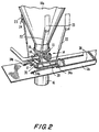
- a vertically-oriented coking vessel 10 is supported by a suitable support structure 12 provided beneath the vessel 10, the structure including a horizontal stationary platform portion 12a all constructed of reinforced concrete or steel.
- Such coking vessels 10 as used in petroleum refinery operations are usually between 6,1 m and 8,5 m (twenty and twenty-eight feet) in diameter, between 22,9 m and 30,5 m (seventy-five and one hundred feet) tall, and have a lower conical shaped portion 10a and a nozzle opening 11 connected to a lower flange 13, which is usually between 1,5 m and 1,8 m (five and six feet) in diameter.
- a removable lower head unit 14 includes an upper cover plate 14a which is attached pressure-tightly to the flange 13 by a plurality of suitable fastener means 15 such as bolts or similar means.
- Coke deposited in the coking vessel 10 during its extended operations in a petroleum refinery is removed from the vessel periodically as needed by removing the lower head unit 14 and cutting the coke from within the vessel.
- the loosened coke falls through the nozzle opening 11 and flange 13 and then through a decoking chute 16 into a storage pit or rail car (not shown) for removal, the decoking chute 16 being removably connectable to the flange 13.
- head unit 14 is attached rigidly by suitable structural members onto a lower cover/cradle skid 17.
- Head unit 14 also includes a feed pipe 18 which is connected to upper cover plate 14a and extends laterally therefrom for use in feeding fluids such as hydrocarbon liquid, steam and water into the coking vessel 10 and for draining fluids from it as needed.
- the head unit 14 and its lower cover/cradle skid 17 are supported by a lifting frame unit 20, which is vertically movable.
- the lifting frame unit 20 is supported from the vessel main stationary support structure 12 by four elongated vertically-oriented hydraulic pressure actuators 22. These four hydraulic actuator cylinders 22 are equally spaced apart, and are each oriented at an angle of between fifteen and forty-five degrees relative to the vertical centerline of vessel 10 and head unit 14. Each actuator cylinder is pivotably attached at its lower end 23 onto the lifting frame unit 20 at its four comers.
- the four actuator cylinders 22 are also each pivotably attached at its upper end 24 to a suitable bracket or embedment plate 25, which is rigidly secured to a vertical member of the vessel support structure 12, as shown in greater detail in Figs. 2 and 3.
- attachments 24 for the four actuator cylinders 22 are determined by the geometry of the lifting frame unit 20 and the decoking chute 16, and the attachments 24 are usually on the flat face of an opening 12b in the support structure 12 through which the vessel conical-shaped portion 10a extends downwardly.
- Such attachment location 24, 25 minimizes undesired heat transfer from the hot coking vessel 10 to the hydraulic actuator cylinder 22.
- suitable auxiliary structural members (not shown) can be provided and the embedment plates 25 can be incorporated to the vessel support structure 12 at appropriate locations on the auxiliary members.
- the four hydraulic actuator cylinders 22 include suitable control means (not shown) which provide for the actuator cylinders to be extended equally and evenly so that the lifting frame unit 20 supporting the head unit 14 is lowered and lifted evenly without any undesired tipping movements.
- Two alignment pins 19 equally spaced apart are provided attached rigidly onto the head unit 14 upper cover 14a to assure accurate alignment of head unit 14 with the lower flange 13 whenever the head unit is raised to contact the vessel lower flange 13.
- the fastener means 15 for head unit 14 onto the vessel lower flange 13 are individual bolts and nuts.
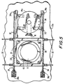
- the lifting frame 20 is provided with four guide tubes 27 located at the comers of the frame and which mate with four alignment pins 28 attached rigidly to the horizontal platform 12a, so as to assure accurate vertical alignment of the lifting frame unit 20 when it is lowered by actuator cylinders 22 onto the platform 12a.
- a cover/cradle unit 30 having dual parallel guide surfaces 32 is interfitted within a central portion of the lifting frame unit 20.
- Dual horizontal extendable actuators 34 are each pivotally attached at their forward ends 34a to one side of the cover/cradle skid unit 30, and are each pivotally attached at their rearward ends 34b onto the horizontal platform portion 12a of the vessel support structure 12.
- These dual actuator attachments to the cover/cradle skid unit 30 provide for the head unit 14 to be moved laterally to a side position on the platform 12a by the dual actuators 34, as shown by Figs. 4 and 5.
- cover/cradle skid unit 30 During the lateral movement of the cover/cradle skid unit 30 to its side position on platform structure 12a, it is supported on the platform structure at its forward end 31 by dual moveable brackets 36 which are guided along dual tracks 38 provided in the platform structure 12a.
- the cover/cradle skid unit 17 is supported at its rearward end by dual support chairs 37 which are attached to and extended upwardly from the platform 12a.
- the lifting frame 20 is supported in its lowered position by the guide tubes 27 which are attached to and extend downward from the lifting frame 20 onto the alignment pins 28.
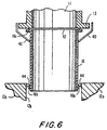
- the lifting frame unit 20 which has the decoking chute 16 attached onto its lower side, is moved upwardly by action of the four vertical actuators 22, so that the upper end of the decoking chute 16 is held firmly and sealed against the lower flanged opening 13 of the coking vessel 10.
- the coking chute 16 extends through a circular opening 12b in the platform 12a.
- the upper end of the decoking chute 16 includes an annular outer sleeve portion 40 which extends upwardly adjacent to the outer periphery of the lower flange 13 of vessel 10, so as to provide a guide means for vertical alignment of the decoking chute 16 with the flange.
- a sealing ring 42 is provided between the upper flange 16a of the chute 16 and the vessel lower flange 13.
- the lower end of decoking chute 16 is also sealed to the opening 12b in platform 12a by a flexible sealing ring 44 which is positioned between an annular projection 16b of the chute 16 and the inner surface of circular opening 12b in the platform structure 12.
- These sealing means 40, 42 and 44 serve to effectively prevent the undesirable escape of steam and hot water from the vessel flange 13 and chute 16.
- the coke accumulated within the vessel 10 is removed through the chute 16 to a storage pit or rail car (not shown) for further handling and use, as generally shown by Fig. 4.
- the lifting frame unit 20 carrying the attached decoking chute 16 is lowered by the four vertically-oriented actuators 22 to its lower position onto the platform 12a.
- the dual horizontal actuators 34 move the cover/cradle skid unit 17 back to its original position so as it interfits with the dual guide surfaces 26 of the lifting frame unit 20.
- the lifting frame unit 20 is lifted upwardly by the four vertical actuators 22, and head unit 14 is vertically guided by the dual alignment pins 19 and returned to its original position with the head unit 14 aligned with the lower flanged opening 13.
- the fastener bolts 15 are replaced to attach the head unit 14 pressure-tightly onto the flange 13, as shown by Figs. 1-3.
Landscapes
- Chemical & Material Sciences (AREA)
- Engineering & Computer Science (AREA)
- Materials Engineering (AREA)
- Oil, Petroleum & Natural Gas (AREA)
- Organic Chemistry (AREA)
- Coke Industry (AREA)
- Filling Or Emptying Of Bunkers, Hoppers, And Tanks (AREA)
- Coating Apparatus (AREA)
- Production Of Liquid Hydrocarbon Mixture For Refining Petroleum (AREA)
Applications Claiming Priority (3)
| Application Number | Priority Date | Filing Date | Title |
|---|---|---|---|
| US683844 | 1996-07-19 | ||
| US08/683,844 US5947674A (en) | 1996-07-19 | 1996-07-19 | Coking vessel unheading device and support structure |
| PCT/US1997/012303 WO1998003611A1 (en) | 1996-07-19 | 1997-07-09 | Coking vessel unheading device and support structure |
Publications (3)
| Publication Number | Publication Date |
|---|---|
| EP0912657A1 EP0912657A1 (en) | 1999-05-06 |
| EP0912657A4 EP0912657A4 (en) | 2000-02-23 |
| EP0912657B1 true EP0912657B1 (en) | 2005-03-23 |
Family
ID=24745686
Family Applications (1)
| Application Number | Title | Priority Date | Filing Date |
|---|---|---|---|
| EP97936073A Expired - Lifetime EP0912657B1 (en) | 1996-07-19 | 1997-07-09 | Coking vessel unheading device and support structure |
Country Status (19)
| Country | Link |
|---|---|
| US (1) | US5947674A (enExample) |
| EP (1) | EP0912657B1 (enExample) |
| JP (1) | JP4372841B2 (enExample) |
| KR (1) | KR100337227B1 (enExample) |
| CN (1) | CN1181158C (enExample) |
| AR (1) | AR007893A1 (enExample) |
| AU (1) | AU3883197A (enExample) |
| BR (1) | BR9710874A (enExample) |
| CA (1) | CA2260929C (enExample) |
| CO (1) | CO4700532A1 (enExample) |
| CZ (1) | CZ295837B6 (enExample) |
| DE (1) | DE69732845T2 (enExample) |
| EA (1) | EA000545B1 (enExample) |
| ES (1) | ES2238727T3 (enExample) |
| ID (1) | ID17812A (enExample) |
| MY (1) | MY143111A (enExample) |
| PL (1) | PL331234A1 (enExample) |
| PT (1) | PT912657E (enExample) |
| WO (1) | WO1998003611A1 (enExample) |
Families Citing this family (35)
| Publication number | Priority date | Publication date | Assignee | Title |
|---|---|---|---|---|
| US6022454A (en) * | 1997-09-17 | 2000-02-08 | Fetzer; Kelly | Remotely operable pressure vessel system |
| US6254733B1 (en) * | 1999-09-01 | 2001-07-03 | Hahn & Clay | Automatic cover removal system |
| US7189310B2 (en) * | 2000-05-12 | 2007-03-13 | Fluor Technologies Corporation | Coke chute systems and methods therefor |
| US8512525B2 (en) * | 2001-03-12 | 2013-08-20 | Curtiss-Wright Flow Control Corporation | Valve system and method for unheading a coke drum |
| US7632381B2 (en) * | 2001-03-12 | 2009-12-15 | Curtiss-Wright Flow Control Corporation | Systems for providing continuous containment of delayed coker unit operations |
| US8123197B2 (en) | 2001-03-12 | 2012-02-28 | Curtiss-Wright Flow Control Corporation | Ethylene production isolation valve systems |
| US6964727B2 (en) * | 2001-03-12 | 2005-11-15 | Curtiss-Wright Flow Control Corporation | Coke drum bottom de-heading system |
| US8282074B2 (en) * | 2001-03-12 | 2012-10-09 | Curtiss-Wright Flow Control Corporation | Delayed coker isolation valve systems |
| US6808602B2 (en) * | 2001-04-25 | 2004-10-26 | Conocophillips Company | Coke drum bottom head removal system |
| US6751852B2 (en) | 2001-05-11 | 2004-06-22 | Foster Wheeler Usa Corporation | Modular pressure vessel unheading and containment system |
| CA2348819C (en) * | 2001-05-25 | 2012-01-03 | Allen S. Malsbury | Hinged bottom cover for unheading a coke drum |
| AU2002342084A1 (en) * | 2001-10-17 | 2003-04-28 | Fluor Corporation | Improved vessel closures and methods therfor |
| US20030127314A1 (en) * | 2002-01-10 | 2003-07-10 | Bell Robert V. | Safe and automatic method for removal of coke from a coke vessel |
| US6843889B2 (en) * | 2002-09-05 | 2005-01-18 | Curtiss-Wright Flow Control Corporation | Coke drum bottom throttling valve and system |
| US8702911B2 (en) * | 2003-02-21 | 2014-04-22 | Curtiss-Wright Flow Control Corporation | Center feed system |
| US7316762B2 (en) | 2003-04-11 | 2008-01-08 | Curtiss-Wright Flow Control Corporation | Dynamic flange seal and sealing system |
| US6926807B2 (en) * | 2003-06-12 | 2005-08-09 | Chevron U.S.A. Inc. | Insulated transition spool apparatus |
| CA2558101C (en) * | 2004-03-17 | 2012-04-24 | Fluor Technologies Corporation | Valve installation apparatus and methods |
| US8679298B2 (en) * | 2004-04-22 | 2014-03-25 | Curtiss-Wright Flow Control Corporation | Remotely controlled decoking tool used in coke cutting operations |
| US7473337B2 (en) | 2004-04-22 | 2009-01-06 | Curtiss-Wright Flow Control Corporation | Remotely controlled decoking tool used in coke cutting operations |
| US7117959B2 (en) * | 2004-04-22 | 2006-10-10 | Curtiss-Wright Flow Control Corporation | Systems and methods for remotely determining and changing cutting modes during decoking |
| US20060042926A1 (en) * | 2004-09-02 | 2006-03-02 | Lu Jinyang J | Cover handling and chute positioning apparatus |
| US7534326B1 (en) * | 2004-09-29 | 2009-05-19 | Conocophillipcs Company | Coke drum bottom unheading system |
| US7819009B2 (en) | 2006-02-28 | 2010-10-26 | Frederic Borah | Vibration Monitoring System |
| US7931044B2 (en) * | 2006-03-09 | 2011-04-26 | Curtiss-Wright Flow Control Corporation | Valve body and condensate holding tank flushing systems and methods |
| JP5021724B2 (ja) * | 2006-05-01 | 2012-09-12 | ホライズン・テクノロジー・インク | サンプル回収システム及び方法 |
| US7871500B2 (en) * | 2008-01-23 | 2011-01-18 | Curtiss-Wright Flow Control Corporation | Coke drum skirt |
| US8440057B2 (en) * | 2008-01-23 | 2013-05-14 | Curtiss-Wright Flow Control Corporation | Linked coke drum support |
| US8545680B2 (en) | 2009-02-11 | 2013-10-01 | Curtiss-Wright Flow Control Corporation | Center feed system |
| US8851451B2 (en) | 2009-03-23 | 2014-10-07 | Curtiss-Wright Flow Control Corporation | Non-rising electric actuated valve operator |
| US8459608B2 (en) | 2009-07-31 | 2013-06-11 | Curtiss-Wright Flow Control Corporation | Seat and valve systems for use in delayed coker system |
| US9850430B2 (en) * | 2013-03-12 | 2017-12-26 | Amec Foster Wheeler Usa Corporation | Method and system for utilizing selectively de-coupleable connections for modular installation of a coke drum |
| EP3475390B1 (en) * | 2016-06-28 | 2021-01-20 | Triplan AG | Arrangement of a coke drum and of a coke crushing unit, for use in a closed, gas-tight system for gaining sellable petroleum coke pieces out of solidified petroleum coke in a coke drum unit and a closed, gas-tight system comprising such arrangement |
| IT201600130758A1 (it) * | 2016-12-23 | 2018-06-23 | Kt – Kinetics Tech Spa | Pezzo di transizione per collegare impianti soggetti a fenomeni di espansione termica molto diversi. |
| DE102020121349A1 (de) * | 2020-08-13 | 2022-02-17 | Z & J Technologies Gmbh | Absperrventil, Verkokungstrommel und Verfahren |
Family Cites Families (8)
| Publication number | Priority date | Publication date | Assignee | Title |
|---|---|---|---|---|
| US2580700A (en) * | 1950-09-21 | 1952-01-01 | Aluminium Lab Ltd | Furnace discharge apparatus |
| US4726109A (en) * | 1986-10-09 | 1988-02-23 | Foster Wheeler Usa Corporation | Unheading device and method for coking drums |
| US4960358A (en) * | 1988-01-26 | 1990-10-02 | Foster Wheeler U.S.A. | Bottom-unheading device and method for vertical vessels |
| US5098524A (en) * | 1988-07-29 | 1992-03-24 | Flour Corporation | Coke drum unheading device |
| US5336375A (en) * | 1989-11-02 | 1994-08-09 | Fluor Corporation | Delayed coker drumhead handling apparatus |
| US5500094A (en) * | 1994-06-30 | 1996-03-19 | The M. W. Kellogg Company | Coke drum deheading device |
| US5628603A (en) * | 1994-11-30 | 1997-05-13 | Fluor Corporation | Automated chute system |
| CA2140380C (en) * | 1995-01-17 | 2000-09-26 | Nobby Rabet | Coke drum deheading system |
-
1996
- 1996-07-19 US US08/683,844 patent/US5947674A/en not_active Expired - Lifetime
-
1997
- 1997-07-09 BR BR9710874-0A patent/BR9710874A/pt not_active IP Right Cessation
- 1997-07-09 PL PL97331234A patent/PL331234A1/xx unknown
- 1997-07-09 AU AU38831/97A patent/AU3883197A/en not_active Abandoned
- 1997-07-09 PT PT97936073T patent/PT912657E/pt unknown
- 1997-07-09 CZ CZ1999169A patent/CZ295837B6/cs not_active IP Right Cessation
- 1997-07-09 WO PCT/US1997/012303 patent/WO1998003611A1/en not_active Ceased
- 1997-07-09 JP JP53473997A patent/JP4372841B2/ja not_active Expired - Lifetime
- 1997-07-09 ES ES97936073T patent/ES2238727T3/es not_active Expired - Lifetime
- 1997-07-09 CN CNB971975701A patent/CN1181158C/zh not_active Expired - Lifetime
- 1997-07-09 DE DE69732845T patent/DE69732845T2/de not_active Expired - Lifetime
- 1997-07-09 EA EA199900142A patent/EA000545B1/ru not_active IP Right Cessation
- 1997-07-09 EP EP97936073A patent/EP0912657B1/en not_active Expired - Lifetime
- 1997-07-09 CA CA002260929A patent/CA2260929C/en not_active Expired - Lifetime
- 1997-07-09 KR KR1019997000365A patent/KR100337227B1/ko not_active Expired - Lifetime
- 1997-07-11 MY MYPI97003149A patent/MY143111A/en unknown
- 1997-07-15 AR ARP970103175A patent/AR007893A1/es active IP Right Grant
- 1997-07-17 CO CO97040419A patent/CO4700532A1/es unknown
- 1997-07-18 ID IDP972499A patent/ID17812A/id unknown
Also Published As
| Publication number | Publication date |
|---|---|
| KR20000067908A (ko) | 2000-11-25 |
| CA2260929A1 (en) | 1998-01-29 |
| AR007893A1 (es) | 1999-11-24 |
| EA000545B1 (ru) | 1999-10-28 |
| EA199900142A1 (ru) | 1999-06-24 |
| US5947674A (en) | 1999-09-07 |
| CN1181158C (zh) | 2004-12-22 |
| JP4372841B2 (ja) | 2009-11-25 |
| MY143111A (en) | 2011-03-15 |
| DE69732845T2 (de) | 2006-04-13 |
| CO4700532A1 (es) | 1998-12-29 |
| AU3883197A (en) | 1998-02-10 |
| CZ16999A3 (cs) | 1999-07-14 |
| JP2001503448A (ja) | 2001-03-13 |
| EP0912657A1 (en) | 1999-05-06 |
| ES2238727T3 (es) | 2005-09-01 |
| PL331234A1 (en) | 1999-07-05 |
| WO1998003611A1 (en) | 1998-01-29 |
| EP0912657A4 (en) | 2000-02-23 |
| DE69732845D1 (de) | 2005-04-28 |
| PT912657E (pt) | 2005-06-30 |
| CZ295837B6 (cs) | 2005-11-16 |
| KR100337227B1 (ko) | 2002-05-17 |
| ID17812A (id) | 1998-01-29 |
| CA2260929C (en) | 2008-01-08 |
| CN1228801A (zh) | 1999-09-15 |
| BR9710874A (pt) | 2000-01-11 |
Similar Documents
| Publication | Publication Date | Title |
|---|---|---|
| EP0912657B1 (en) | Coking vessel unheading device and support structure | |
| US4960358A (en) | Bottom-unheading device and method for vertical vessels | |
| JPH05201487A (ja) | コークスドラムの底ぶたを着脱する装置および方法 | |
| EP0265096B1 (en) | Unheading device and method for coking drums | |
| US20020166862A1 (en) | Modular pressure vessel unheading and containment system | |
| US5500094A (en) | Coke drum deheading device | |
| CA1324973C (en) | Bottom unheading device and method for vertical vessels | |
| US6808602B2 (en) | Coke drum bottom head removal system | |
| CN1914003B (zh) | 去头阀安装系统和方法 | |
| CA2580354C (en) | Coke drum bottom unheading system and method |
Legal Events
| Date | Code | Title | Description |
|---|---|---|---|
| PUAI | Public reference made under article 153(3) epc to a published international application that has entered the european phase |
Free format text: ORIGINAL CODE: 0009012 |
|
| 17P | Request for examination filed |
Effective date: 19990119 |
|
| AK | Designated contracting states |
Kind code of ref document: A1 Designated state(s): DE ES FI GB PT SE |
|
| AX | Request for extension of the european patent |
Free format text: RO PAYMENT 19990119 |
|
| A4 | Supplementary search report drawn up and despatched |
Effective date: 20000111 |
|
| AK | Designated contracting states |
Kind code of ref document: A4 Designated state(s): DE ES FI GB PT SE |
|
| RIC1 | Information provided on ipc code assigned before grant |
Free format text: 7C 10B 33/14 A, 7C 10B 25/10 B, 7C 10B 33/00 B |
|
| 17Q | First examination report despatched |
Effective date: 20031106 |
|
| GRAP | Despatch of communication of intention to grant a patent |
Free format text: ORIGINAL CODE: EPIDOSNIGR1 |
|
| GRAS | Grant fee paid |
Free format text: ORIGINAL CODE: EPIDOSNIGR3 |
|
| GRAA | (expected) grant |
Free format text: ORIGINAL CODE: 0009210 |
|
| AK | Designated contracting states |
Kind code of ref document: B1 Designated state(s): DE ES FI GB PT SE |
|
| AX | Request for extension of the european patent |
Extension state: RO |
|
| REG | Reference to a national code |
Ref country code: GB Ref legal event code: FG4D |
|
| REF | Corresponds to: |
Ref document number: 69732845 Country of ref document: DE Date of ref document: 20050428 Kind code of ref document: P |
|
| REG | Reference to a national code |
Ref country code: PT Ref legal event code: SC4A Free format text: AVAILABILITY OF NATIONAL TRANSLATION Effective date: 20050429 |
|
| REG | Reference to a national code |
Ref country code: SE Ref legal event code: TRGR |
|
| REG | Reference to a national code |
Ref country code: ES Ref legal event code: FG2A Ref document number: 2238727 Country of ref document: ES Kind code of ref document: T3 |
|
| PLBE | No opposition filed within time limit |
Free format text: ORIGINAL CODE: 0009261 |
|
| STAA | Information on the status of an ep patent application or granted ep patent |
Free format text: STATUS: NO OPPOSITION FILED WITHIN TIME LIMIT |
|
| 26N | No opposition filed |
Effective date: 20051227 |
|
| PGFP | Annual fee paid to national office [announced via postgrant information from national office to epo] |
Ref country code: PT Payment date: 20160623 Year of fee payment: 20 |
|
| PGFP | Annual fee paid to national office [announced via postgrant information from national office to epo] |
Ref country code: DE Payment date: 20160726 Year of fee payment: 20 Ref country code: GB Payment date: 20160727 Year of fee payment: 20 Ref country code: FI Payment date: 20160727 Year of fee payment: 20 |
|
| PGFP | Annual fee paid to national office [announced via postgrant information from national office to epo] |
Ref country code: SE Payment date: 20160727 Year of fee payment: 20 |
|
| PGFP | Annual fee paid to national office [announced via postgrant information from national office to epo] |
Ref country code: ES Payment date: 20160726 Year of fee payment: 20 |
|
| REG | Reference to a national code |
Ref country code: DE Ref legal event code: R071 Ref document number: 69732845 Country of ref document: DE |
|
| REG | Reference to a national code |
Ref country code: GB Ref legal event code: PE20 Expiry date: 20170708 |
|
| PG25 | Lapsed in a contracting state [announced via postgrant information from national office to epo] |
Ref country code: PT Free format text: LAPSE BECAUSE OF EXPIRATION OF PROTECTION Effective date: 20170718 Ref country code: GB Free format text: LAPSE BECAUSE OF EXPIRATION OF PROTECTION Effective date: 20170708 |
|
| REG | Reference to a national code |
Ref country code: ES Ref legal event code: FD2A Effective date: 20180508 |
|
| PG25 | Lapsed in a contracting state [announced via postgrant information from national office to epo] |
Ref country code: ES Free format text: LAPSE BECAUSE OF EXPIRATION OF PROTECTION Effective date: 20170710 |