EP0912449B1 - Methode zur biologischen reinigung von verunreinigtem wasser - Google Patents
Methode zur biologischen reinigung von verunreinigtem wasser Download PDFInfo
- Publication number
- EP0912449B1 EP0912449B1 EP97929139A EP97929139A EP0912449B1 EP 0912449 B1 EP0912449 B1 EP 0912449B1 EP 97929139 A EP97929139 A EP 97929139A EP 97929139 A EP97929139 A EP 97929139A EP 0912449 B1 EP0912449 B1 EP 0912449B1
- Authority
- EP
- European Patent Office
- Prior art keywords
- zone
- biological treatment
- zones
- mixing
- clarifying
- Prior art date
- Legal status (The legal status is an assumption and is not a legal conclusion. Google has not performed a legal analysis and makes no representation as to the accuracy of the status listed.)
- Expired - Lifetime
Links
Images







Classifications
-
- C—CHEMISTRY; METALLURGY
- C02—TREATMENT OF WATER, WASTE WATER, SEWAGE, OR SLUDGE
- C02F—TREATMENT OF WATER, WASTE WATER, SEWAGE, OR SLUDGE
- C02F3/00—Biological treatment of water, waste water, or sewage
- C02F3/02—Aerobic processes
- C02F3/12—Activated sludge processes
- C02F3/1236—Particular type of activated sludge installations
- C02F3/1242—Small compact installations for use in homes, apartment blocks, hotels or the like
- C02F3/1247—Small compact installations for use in homes, apartment blocks, hotels or the like comprising circular tanks with elements, e.g. decanters, aeration basins, in the form of segments, crowns or sectors
-
- C—CHEMISTRY; METALLURGY
- C02—TREATMENT OF WATER, WASTE WATER, SEWAGE, OR SLUDGE
- C02F—TREATMENT OF WATER, WASTE WATER, SEWAGE, OR SLUDGE
- C02F3/00—Biological treatment of water, waste water, or sewage
- C02F3/02—Aerobic processes
- C02F3/12—Activated sludge processes
- C02F3/1205—Particular type of activated sludge processes
- C02F3/121—Multistep treatment
-
- C—CHEMISTRY; METALLURGY
- C02—TREATMENT OF WATER, WASTE WATER, SEWAGE, OR SLUDGE
- C02F—TREATMENT OF WATER, WASTE WATER, SEWAGE, OR SLUDGE
- C02F3/00—Biological treatment of water, waste water, or sewage
- C02F3/30—Aerobic and anaerobic processes
-
- C—CHEMISTRY; METALLURGY
- C02—TREATMENT OF WATER, WASTE WATER, SEWAGE, OR SLUDGE
- C02F—TREATMENT OF WATER, WASTE WATER, SEWAGE, OR SLUDGE
- C02F3/00—Biological treatment of water, waste water, or sewage
- C02F3/30—Aerobic and anaerobic processes
- C02F3/302—Nitrification and denitrification treatment
-
- Y—GENERAL TAGGING OF NEW TECHNOLOGICAL DEVELOPMENTS; GENERAL TAGGING OF CROSS-SECTIONAL TECHNOLOGIES SPANNING OVER SEVERAL SECTIONS OF THE IPC; TECHNICAL SUBJECTS COVERED BY FORMER USPC CROSS-REFERENCE ART COLLECTIONS [XRACs] AND DIGESTS
- Y02—TECHNOLOGIES OR APPLICATIONS FOR MITIGATION OR ADAPTATION AGAINST CLIMATE CHANGE
- Y02A—TECHNOLOGIES FOR ADAPTATION TO CLIMATE CHANGE
- Y02A20/00—Water conservation; Efficient water supply; Efficient water use
- Y02A20/20—Controlling water pollution; Waste water treatment
- Y02A20/208—Off-grid powered water treatment
-
- Y—GENERAL TAGGING OF NEW TECHNOLOGICAL DEVELOPMENTS; GENERAL TAGGING OF CROSS-SECTIONAL TECHNOLOGIES SPANNING OVER SEVERAL SECTIONS OF THE IPC; TECHNICAL SUBJECTS COVERED BY FORMER USPC CROSS-REFERENCE ART COLLECTIONS [XRACs] AND DIGESTS
- Y02—TECHNOLOGIES OR APPLICATIONS FOR MITIGATION OR ADAPTATION AGAINST CLIMATE CHANGE
- Y02W—CLIMATE CHANGE MITIGATION TECHNOLOGIES RELATED TO WASTEWATER TREATMENT OR WASTE MANAGEMENT
- Y02W10/00—Technologies for wastewater treatment
- Y02W10/10—Biological treatment of water, waste water, or sewage
Definitions
- the present invention relates to a method of biologically cleaning polluted water by employing active sludge and at least three zones, where at least one of said zones operates as a permanent biological treatment zone and at least two of said zones variably operate as a biological treatment zone and a clarifying zone.
- biological treatment zone for an area or a section of for instance a container, a vessel, a reactor, a channel or a tank, wherein biologically active sludge is kept suspended by way of for instance a mechanical stirring or aeration under such aerobic or anaerobic conditions that the microorganisms present in the sludge consume the impurities in the water.
- sedimentation zone an area or section of for instance a container, a vessel, a reactor, a channel or a tank which is only exposed to an insignificant or no mechanical effect at all in such a manner that active sludge can settle.
- clarifying zone an area or section of for instance a container, a vessel, a reactor, a channel or a tank in which active sludge applies essentially in the settled state, and from which the cleaned water is decanted and drained off.
- back-mix is used for any process allowing a transfer of material from a first zone to a second zone while material is simultaneously being transferred from the second zone into the first zone.
- the "back-mix ratio" of a predetermined clarifying or sedimentation zone during a specific period is defined as the ratio of the volume amount of material (water with sludge suspended therein) being transferred with back-mixing from said zone during said period to another zone relative to the total volume of said clarifying and sedimentation zone.
- DK-PS No. 131,181 discloses a method of the above type, where said method is ordinarily called the triple channel method or the T-channel method.
- This method employs three containers 1, 2 and 3.
- One container (container 2) operates as a permanent aeration zone, and the two remaining containers (i.e. containers 1 and 3) operate variably as aeration zone and clarifying zone.
- the three containers are connected to a common source for the feeding of waste water in such a manner that the feeding of waste water can alternate between the three containers.
- the containers are furthermore interconnected two by two.
- container 1 When the triple channel is operated, container 1 operates during a first period as an aeration zone being fed with waste water while container 3 operates as a clarifying zone from which cleaned water is drained out. During a succeeding second period, waste water is fed to container 2 while container 1 still operates as an aeration zone and container 3 as a clarifying zone from which cleaned water is drained out. During a third period, the aeration is stopped in container 1 while waste water is still being fed to container 2 and cleaned water is being drained out of container 3. Subsequently, during a fourth period waste water is fed to container 3 which during this period operates as an aeration zone while container 1 operates as a clarifying zone from which cleaned water is drained out.
- the waste water is fed to container 2 while container 3 still operates as an aeration zone and container 1 as a clarifying zone from which cleaned water is drained out.
- the aeration in container 3 is stopped while waste water is still being fed to container 2 and cleaned water is drained out of container 1.
- This cycle including 6 periods is repeated over and over again.
- the patent description refers to a preferred embodiment where the total operational cycle lasts 8 hours.
- the periods 1 and 3 lasts 2 times 2 hours, and the periods 2, 3, 5, and 6 last 4 times 1 hour.
- DK-PS No. 131,279 describes a method for denitrification of waste water by employing a triple channel system. This method is usually called the "BioDenitro"-method and is based on the same operational pattern as the triple channel described above.
- the biological treatment is, however, carried out in container 1 and 3 and alternately under anaerobic and aerobic conditions. Aerobic conditions are provided by the container in question being subjected to an aeration, whereas anaerobic conditions are provided by a relatively gentle stirring being performed in the container. Both functions can according to this Patent Specification be provided by a rotor installed in the container, said rotor running at a variable speed.
- the T-channel method is, however, encumbered with a number of draw--backs:
- the waste water is fed to a container which later on is used as a clarifying container.
- the aeration must continue for a period after termination of the feeding of waste water to said container in order to ensure that the required cleanness of the outlet is obtained.
- the utilization of the aerators is unfortunately relatively low.
- the oxygen demand applying to the indicated operational pattern is distributed with 31 % to each of the clarifying zones and 38% to the permanent biological treatment zone.
- the degree of utilization of the total aeration installation is therefore only 49%, because 62% of the oxygen demand applies to the zones where the aerators are stopped part of the time, i.e. 5 out of 8 hours in the operational pattern dealt with.
- the mean concentration of sludge i.e. the average of the three containers
- the mean concentration of sludge is relatively low because sludge has a tendency to accumulate in the side channels.
- the critical concentration of sludge of approximately 7 kg/m is easily exceeded when an mean concentration of sludge of more than approximately 4 kg/m 3 is involved.
- DK-PS No. 123,814 discloses a method of cleaning waste water, said method ensuring a much better utilization of the aerators than the T-channel method.
- This method is ordinarily called the alternate channel or the V-channel method, and here a single container is divided into a main aeration part and two channel parts individually serving either as an aeration zone or as a clarifying zone.
- the aerators are arranged in the main aeration part continuously being fed with waste water.
- a typical operational pattern of this method includes the following four periods:
- one channel part operates as an aeration zone and the other channel part as a clarifying zone. Then the aerators are stopped for one hour during a second period.
- the second channel part operates as an aeration zone and the first channel part as a clarifying zone. Then the aerators are stopped for one hour during a fourth period, and the described operational cycle is repeated.
- the aerators are only stopped during the periods involving preparation of one channel part for the clarifying function, and the described operational pattern results in a degree of utilization of the aerators of 75%.
- the V-channel method is only used in a few waste water cleaning plants mainly on account of the structural limitations.
- the degree of freedom applying to the structural embodiment is limited, and it is not a good idea to position more than maximum two aerators in a plant section.
- V-channel method Another draw-back of the V-channel method is that the building depth is limited to 2.5 to 3 m, where large plants have a demand for building depths of 4 to 8 m in order to reduce the initial expenditure and the area need. Furthermore, like the T-channel method an extensive accumulation of sludge takes place during the relatively long clarifying period inside the clarifying zone with the effect that the rating of the plant for a maximum mean concentration of sludge is subject to limitations. Both V and T-channels are ordinarily rated for a maximum mean concentration of sludge of approximately 4 kg/m 3 .
- FIG. 1 of the drawing Another known method ensuring a high utilization of the aerators appears from Fig. 1 of the drawing.
- waste water is fed into a biological reactor including aeration units.
- the clarification is carried out by a permanent post-clarifying vessel, and the aerators in the biological reactor can therefore be utilized 100% of the time.
- the sludge being separated in the post-clarifying vessel must be returned by way of pumping to the biological reactor.
- the latter return flow increases, however, the water flow from the biological reactor to the post-clarifying vessel and consequently the amount of sludge transported thereto and separated therein is increased as well.
- the sedimentation inside the post-clarifying vessel results in a concentration of the sludge. This process is, however, carried out relatively slowly, and in practice it is not possible to achieve a concentration of sludge in the return flow of more than 8 to 10 kg/m 3 .
- DK-PS No. 131,279 describes a plant comprising two biological reactors which alternately are run aerobically and anaerobically, as well as a permanent post-clarifying vessel.
- This plant allows a denitrification of waste water, but it is, however, encumbered with the same draw-backs as the plant described above as far as the capacity is concerned.
- the denitrification is carried out in only one step.
- the first step operates at high rates and a relatively high concentration of impurities.
- the object of the present invention is to provide a method of biologically cleaning polluted water, whereby the draw-backs of the methods described above have been overcome.
- the back-mixing may by the present invention be carried out to a very varying extent. However, it turned out surprisingly that even with a relatively small back-mix ratio it is possible to obtain a neutralisation of the differences in sludge concentration between the permanent biological treatment zone and the zone earlier having operated as a clarifying zone, said neutralization being sufficient for keeping the sludge concentrations in the clarifying zones below the critical value of approximately 7 kg/m 3 , at which a risk of sludge extraction applies.
- a particular embodiment of the method according to the invention employs a permanent biological treatment zone and two zones variably operating as a biological treatment zone and a clarifying zone, said latter zones being individually hydraulically connectec to the permanent biological treatment zone.
- VT-channel method employs a permanent biological treatment zone and two zones variably operating as a biological treatment zone and a clarifying zone, said latter zones being individually hydraulically connectec to the permanent biological treatment zone.
- a preferred operational pattern of this embodiment includes a cycle involving the following four periods:
- one variable zone operates as a biological treatment zone while the second variable zone (zone 3) operates as a clarifying zone.
- zone 1 operates as a sedimentation zone while zone 3 still operates as a clarifying zone.
- zone 3 operates as a biological treatment zone while zone 1 operates as a clarifying zone.
- zone 3 operates as a sedimentation zone while zone 1 still operates as a clarifying zone. Then during a fourth period, zone 3 operates as a sedimentation zone while zone 1 still operates as a clarifying zone. Then the described cycle is repeated.
- the concentration of sludge rises in zone 3 during the first and the second period due to the transport of sludge from the permanent biological treatment zone to zone 3.
- the back-mixing implies that the differences in concentrations are neutralized between zone 3 and the permanent treatment zone with the effect that the concentration of sludge decreases in zone 3. In this manner a suitable sludge balance is maintained in the plant.
- the neutralization of the sludge concentrations between the zones is independent of the flow of entering polluted water, which accordingly can be fed continuously to the permanent biological treatment zone.
- the oxygen demand is high in the very zone where the aerators run permanently, and the oxygen demand is low in the zones used for clarification during part of the time.
- the described embodiment presents an oxygen demand of 18% in each of the variable treatment/clarifying zones and of 64% in the permanent biological treatment zone.
- the degree of utilization of the aerator installation is thus 63% for an operational pattern where a variable zone initially operates as a biological treatment zone for three hours and then as a sedimentation zone for one hour and finally as a clarifying zone for four hours (below called a 3,1,4-phase pattern).
- Table II compares the utilization of the aerators of a T-channel (prior art) with the method according to the invention for three different phase patterns.
- Phase pattern(treat. sed., cla.) Operating period of aerators in a variable zone (%) Yield of an aerator installation (%) T-channel (comp.) acc. to the invention T-channel (comp.) acc. to the invention 3,1,4 37.5 37.5 49 63 2,1,3 33.3 33.3 45 58 1,1,2 25 25 35 48
- a shortening of the clarifying phases has only an insignificant effect on the degree of utilization of the aerators.
- a shortening of the clarifying phases has the effect that the operating period of the aerators in the variable zones only lasts for a minor part of a phase course because the reduction of the operational period has only an effect on a minor section of the total plant including the aeration installation.
- a shortening of the period involving a feeding of sludge to the clarifying zone has the effect that the transport of sludge is reduced.
- a 1,1,2-phase pattern allows for instance achievement of a mean concentration of sludge of 4.7 to 5 kg/m 3 .
- a major advantage of the method according to the invention is that polluted water is never fed to a container which later on is to operate as a clarifying zone.
- a relatively low back-mix ratio is employed, such as below 2, it is furthermore possible to ensure both that the major portion of the conversion takes place in the permanent biological treatment zone and that only a minor portion of said conversion takes place in the variable zones.
- the permanent biological treatment zone and the variable zones operate as a two-step biological reactor, where the first step involves relatively high concentrations of pollution and a high reaction rate and the second step involves low concentrations of pollution and a low reaction rate.
- the denitrification in a sedimentation phase continues at the same rate as in a zone operating as a treatment zone, at least at the beginning of said sedimentation phase where the sludge sinks to the bottom and causes a turbulence in the surrounding water.
- organic substances and nitrate are converted in the sludge flocks, said organic substances and nitrate haveing been absorbed in the sludge while said sludge was suspended and in optimum contact with the polluted water during a previous biological treatment period.
- This denitrification can, however, only continue for a limited period before the sludge and polluted water are to be remixed.
- an advantage of the present invention is that it operates with short phases.
- An embodiment of the invention renders it possible to reduce the clarifying phases of a clarifying zone to approximately one hour, and this embodiment is particularly suited in connection with BioDenitro-operation.
- This embodiment is according to the invention obtained by interconnecting two of the above described plants (VT-channels), each of these plants including a permanent biological treatment zone and two variable treatment/clarifying zones. The interconnection is established by way of a hydraulic connection between the two permanent biological treatment zones, and the two plants are driven in counterphase.
- An embodiment of the invention including a plant with two interconnected V-channels driven in counterphase renders it possible to obtain a utilization degree of the aerators of 100%.
- this embodiment furthermore implies that the polluted water is alternately fed to one and the other V-channel, and that the inlet zone is anaerobically run while the second permanent treatment zone is aerobically run, it turned out to be possible to obtain ideal phase periods for the denitrification process and at the same time to obtain a cleaning in two steps.
- Another embodiment of the invention employing a plant with a permanent biological treatment zone, two variable treatment/clarifying zones as well as a permanent post-clarifying zone turned out to allow an increase of the concentration of sludge and at the same time a relatively low transport of sludge to the permanent post-clarifying zone in such a manner that the return flow of sludge from the post-clarifying zone to the permanent treatment zone can be kept at a low level compared to known plants with a permanent post-clarifying vessel.
- the presence of a permanent post-clarifying zone implies that it is not necessary to run the variable treatment/clarifying zones in order to obtain a total retaining of the sludge therein.
- the sludge concentrations in these zones can therefore be increased, and the phase preparing a zone for clarification by way of sedimentation without an outlet can be shortened or completely cut out.
- Fig. 2 shows a plant for carrying out the method according to the invention, said plant comprising three containers, where container 1 and 3 are variable treatment/clarifying zones, and container 2 is a permanent biological treatment zone.
- Container 1 and 3 are provided with openings a and a' to container 2, and in front of these openings a capture plate is arranged, said plate cutting off a partial flow and pressing said partial flow into the second container when the water in container 1 or 3 is set in horizontal circular flow.
- a capture plate is arranged, said plate cutting off a partial flow and pressing said partial flow into the second container when the water in container 1 or 3 is set in horizontal circular flow.
- the openings b and b' are shaped such that water is not pressed into container 1 or 3 in connection with the horizontal circular flow inside container 2.
- the water only passes between container 2 and container 1 or 3 when the circular flow inside container 1 or 3 is set in motion.
- the openings are advantageously shaped such that the collecting openings a and a' in container 1 and 3 are provided at the bottom of the containers, and the openings b and b' are provided at the surface.
- Container 1 and 3 are provided with both aerators or stirrers and with an automatic overflow for discharging cleaned water in a clarifying phase. These overflows are closed when the associated container operates as a biological treatment zone or as a sedimentation zone.
- the aerators in container 1 have been activated in such a manner that a back-mixing is carried out between container 1 and 2.
- the overflow c in container 1 is closed whereas the overflow c' in container 3 is open, the latter container operating as a clarifying zone.
- the overflow c in container 1 is opened while the overflow c' in container 3 is closed.
- the circular flow is simultaneously started in said container 3 in such a manner that water is exchanged between container 3 and container 2 whereby sludge is returned to container 2, said sludge being accumulated in container 3 in phase A and B.
- phase B This phase is laterally reversed relative to phase B, and during this phase the aerators in container 3 are stopped while the overflow c' is kept closed and the overflow c is kept open. During this phase, sludge settles in container 3 with the effect that a succeeding clarifying function for container 3 is prepared.
- All phases involve a feeding of waste water to container 2, wherein the aerators are activated 100% of the time.
- Fig. 3 shows a plant for carrying out the method according to the invention, said plant comprising three containers, where the containers 1 and 3 are variable treatment/clarifying zones, and container 2 is a permanent biological treatment zone.
- This plant is driven analogously with the procedure described for the plant shown in Fig. 2.
- the embodiment of the plant shown is, however, particularly advantageous in connection with high back-mix ratios. When the back-mix ratio is 4 or more, independent aerators need not be arranged in the variable zones because it is sufficient to install horizontal propellers for propelling the water. As a result, the initial expenditures are reduced.
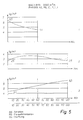
- Fig. 4 is a graphic view of the variation in the concentration of sludge in container 1 during phase A and by means of the method according to the invention illustrated in Fig. 2 or Fig. 3 involving various back-mix ratios.
- the container volume is 3000 m 3 for each of the three containers, and the influx of polluted water to container 2 is 1000 m 3 per hour.
- the back-mix ratio is defined as the amount of water pressed into container 2 from container 1 per time unit and which accordingly is exchanged between said container 1 and said container 2, said amount of water being divided by the volume of container 1.
- a back-mix ratio of 1 in the present case corresponds to an exchange of 3000 m 3 /h between container 1 and container 2, i.e. the volume of container 1 is exchanged by the volume of container 2 one time per hour.
- phase A lasts two hours and phase B lasts one hour, i.e. container 3 operates as a clarifying vessel for three hours.
- the back-mix ratio is 1/3, i.e. approximately 0.33.
- a final concentration of 6.9 kg/m 3 in a clarifying vessel i.e. close to the critical limit (7 kg/m 3 ) results in an mean concentration of sludge in the plant of 4.4 kg/m 3 .
- the mean concentration must be reduced to less than 4 kg/m 3 in order not to exceed the critical concentration of sludge.
- phase A is instead reduced to one hour corresponding to a clarifying period of 2 hours, the concentration of sludge only reaches 6.5 kg/m despite a relatively high mean concentration of sludge of 4.5 kg/m 3 .
- the examples E3, E4 and E5 use a 1,1,2-operational pattern, an mean concentration of sludge of 4.5 kg/m 3 and a back-mix ratio of 1, 2 and 4, respectively. It appears from the curves indicated that an increase of the back-mix ratio results in a faster transfer of sludge from container 1 to container 2, and furthermore that most of the transport takes place during the first part of the period. Thus the transport of sludge is minimal during the last 20 minutes of E3 and the last 40 minutes of E5. In addition it appears that the final concentration in the clarifying zone following a clarifying period is higher in E5 than in E3 because the sludge is transferred faster to container 2 and consequently also carried faster on to the clarifying zone (container 3).
- both high back-mix ratios and long clarifying periods are disadvantageous for the clarifying function because both factors involve an increased transport of sludge to the clarifying zone.
- a low back-mix ratio like in E1 and E2 results, however, in a low concentration of sludge in the permanent biological treatment zone, more specifically 2.25 and 2.05 kg/m 3 , respectively, where E3, E4 and E5 ensure 3.3, 3.5 and 3.7 kg/m 3 , respectively.
- a back-mix ratio of approximately 1 and a phase period for phase A land C) of approximately one hour renders it possible to use a mean concentration of sludge of up to approximately 5 kg/m without exceeding the critical limit. At the same time a sufficient concentration of sludge is obtained in the permanent biological treatment zone.
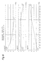
- FIGs. 5 and 6 are graphic views of the concentration of sludge in containers 1, 2 and 3 versus the period relative to a 1,1,1 and a 2,1,3-operational pattern, respectively.
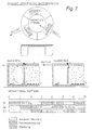
- Fig. 7 outlines a plant and an operational pattern for carrying out a particular embodiment of the invention employing a permanent biological treatment zone and three variable treatment/clarifying zones.
- the diffusers a can be uniformly distributed across the entire bottom inside the permanent biological treatment zone with the result that no circulating water movements are caused inside this container. The resulting transfer of oxygen per kWh is higher than in connection with ordinary rotor aerators.
- the diffusers b are arranged in one side of the container which results in a vertical, circulating water flow when air is blown through said diffusers.
- the number of diffusers is adapted such that both a suitable water circulation and an aeration meeting the oxygen demand inside the clarifying zone are obtained.
- the air is supplied by a central compressor by way of a valve readjustment.
- the present embodiment uses three variable zones, it is possible to employ a short phase cycle, such as one hour aeration, one hour sedimentation, and one hour clarification.
- a short phase cycle such as one hour aeration, one hour sedimentation, and one hour clarification.
- the volume of each variable zone is 2000 m 3 , i.e. 2/3 of the volume of a variable zone in the plant with two variable zones.
- the clarifying period of the above phase cycle has been halved from two hours to one hour, less sludge is accumulated in the variable zones and the mean concentration of sludge can be increased.
- the present embodiment may, especially in deep vessels, involve some transport of sludge from the clarifying zone to the permanent biological treatment zone during the clarifying phase.
- the latter is due to the difference in specific gravity between sludge and the aerated water in the biological zone because the pressure from the settling sludge presses the sludge through the openings in the bottom.
- Such an effect implies that the concentration of sludge in the variable zones can hardly reach the critical limit of 7 kg/m 3 .
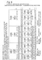
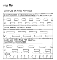
- Fig. 8 outlines a plant and two operational patterns for carrying out a particular embodiment of the invention employing a permanent biological treatment zone and four variable treatment/clarifying zones. It appears from the operational pattern that it is possible to let a clarifying zone continue its operation for a period after the variable zone has started its function, said zone operating as a clarifying zone in the subsequent phase.
- An overlapping clarifying operation is particularly useful when it is desired to obtain an increased clarifying capacity, such as by way of an increased water flow in rainy weather.
- two variable clarifying zones to operate with an overlapping sedimentation.
- the advantage of using three or more zones is that it is possible to use such an operational pattern without the clarifying period for each clarifying zone growing unsuitably long.
- Fig. 9 illustrates an embodiment of the method according to the invention with two interconnected modules, where each module comprises a permanent biological treatment zone and two variable treatment/clarifying zones(corresponding to the plants shown in Figs. 2 and 3), More specifically, the two modules are interconnected at the two permanent biological treatment zones, i.e. container 2 is hydraulically coupled to container 5.
- the two permanent zones can be connected with an opening when they are built together in the position shown in the Figure, or they can be interconnected by way of a channel provided the modules are arranged side by side.
- the inlet can be uniformly distributed between the two permanent treatment zones when it is desired preferably to remove organic substance, or the inlet can be changed between said two permanent treatment zones, and anaerobic conditions can be established in the inlet zone when denitrification operation is desired.
- the basic pattern of denitrification operation including the four phases A, B, C and D with a period of each phase lasting one hour appears from the top of the Figure.
- the four clarifying zones succeed one another in such a manner that the clarifying period of each zone has been reduced to one hour.
- the one hour phases used in the basic pattern are not optimal because most of the conversion is performed in a relatively short period with the result that the remaining period is wasted time.
- the phases can, however, be subdivided, cf. A1, A2, A3 and B1, B2, B3 etc.
- the time division and the number of divisions can be varied in response to the conditions.
- the variable zones operate in the basic pattern with one hour biological treatment with back-mixing under aerobic conditions before the one-hour sedimentation phase starts. During this phase the remaining nitrate is removed before the overflow is opened and the one-hour clarifying phase is started.
- the pattern with the short phases, cf. below, implies that an increased portion of the denitrification takes place before the sedimentation phase is started.
- a variable zone is always operated as an aerobic treatment zone during the period up to the sedimentation phase, and the remaining nitrogen is therefore present in nitrate form.
- a dynamic system is provided which is based on a simple basic module, and which in an ideal manner meets the process conditions applying to varying load conditions and outlet requirements.
- Fig. 10 illustrates an embodiment of the method according to the invention with two interconnected plants of the type shown in Fig. 3,
- the rotors must be stopped during the operation of the one-hour phases A, B, C, D each time a variable zone is to be prepared for the clarifying function.
- Fig. 11 illustrates an embodiment of the method according to the inventi on employing one plant with a permanent biological aeration zone, two variable treatment/clarifying zones as well as a permanent post-clarifying zone.
- the concentration of sludge in the flow to the permanent post-clarifying vessel is 2 kg/m 3 .
- the latter necessitates a recirculation of the sludge from the permanent post-clarifying vessel to the permanent treatment zone of 350 m 3 /h, which is significantly less than the 1000 m 3 /h required by the prior art shown in Fig. 1.
- the amount of sludge to be separated per hour by the post-clarifying vessel is only 2800 kg compared to 8000 kg for the prior art shown in Fig. 1.
- a further advantage of the present embodiment is that the mean concentration of sludge in the permanent treatment zone and the variable treatment/clarifying zones is 5.5 kg/m 3 compared to 4 kg/m 3 in the plant in Fig. 1.
- a running of the plant shown in Fig. 1 with a concentration of sludge of 5.5 kg/m 3 necessitates a recirculation of sludge of 2.1 times the inlet of waste water, i.e. 6200 m 3 /h, which is quite unrealistic.
- the cycle of a variable treatment/clarifying zone is in the example 40 minutes biological treatment with a back-mix ratio of 1, 20 minutes sedimentation without outlet and 60 minutes clarification with outlet to the permanent clarifying zone.
- the possibility of operating with a high concentration of sludge has been utilized in order to limit the volume of the plant.
- variable clarifying zones can be obtained for plants of this type, cf. above, and therefore it is also possible to dimension the plant such that the discharge takes place directly from a variable clarifying zone during some of the period in such a manner that the permanent clarifying zone is relieved and can be of a reduced size.
- the periods are extended in which the variable zones operate as biological treatment zones, it is not necessary to involve a back-mixing during the entire period out of respect for the sludge balance, and accordingly it is possible to insert short sedimentation phases in this period where an additional denitrification takes place.
- Optimum conditions for the denitrification require a division of the permanent biological treatment zone into two parts, and the influx alternates between said parts at the same time as anaerobic conditions are provided in the influx zone.
- the latter appears from Fig. 12 outlining a plant and an operational pattern for carrying out a particular embodiment of the invention employing two permanent biological treatment zones, two variable treatment/clarifying zones and optionally a permanent post-clarifying zone,
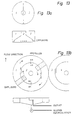
- Fig 13a shows an advantageous embodiment of the basic module for the plant with 6 to 10 m deep vessels.
- 2 refers to the permanent aeration vessel while 1 and 3 are variable zones.
- the illustrated embodiment ensures a large surface in the clarifying zones, from which the cleaned water is to be decanted, and the major portion of the aeration vessel is positioned in the deep portion with the maximum oxygen uptake.
- the inclining bottom in the clarifying zones implies that the sludge sinks in the still periods and is pressed by way of gravitation back to the aeration vessel 2.
- Fig. 13 b shows an advantageous embodiment with very large vessels, where a horizontal water flow may present an advantage.
- This embodiment can be used in connection with both flat and deep vessels.
- the variable treatment/clarifying zone is placed in the middle, 2 and 4, and the permanent treatment zone is placed in the outer ring, 1 and 3.
- the units for the aeration/stirring inside both the inner cylinder and the outer ring can be diffusers/propellers or rotors. It is simple procedure to build the central cylinder with a bottom inclining towards the centre. Then the sludge flows towards the deepest location during the sedimentation phases, and a recirculation flow can be established with a high concentration from this location. As a result, the clarifying periods can be extended without involving an overflow of sludge, but the back-mixing in the treatment phases is still a necessity.
- Fig. 14 shows a float closure which particularly advantageously can be used in a variable treatment/clarifying zone in connection with the emptying of cleaned water therefrom while carrying out the method according to the invention.
- the float closure comprises one or more nozzles 1 arranged at the water surface and provided with float bodies 2, such as a ball or a pipe closed at both ends.
- the nozzles are arranged on a pipe 3 extending to a discharge chamber provided with an automatic valve or an overflow rim 4.
- the overflow rim 4 When the overflow rim 4 is opened, the water level is lowered with the result that the float body is lowered too and allows a free passage through the nozzles 1.
- the overflow rim 4 is closed, the water level in 3 rises and the float bodies rise so as to close the nozzles.
- An overpressure can optionally be established by placing a small pump 5 in the discharge chamber and by pumping water into 3.
- the pipe 3 must then be provided with an overflow 7 for adjustment of the pressure in 3.
- the advantage of the described float closure is that is operated merely by means of an automatic valve and optionally a small pump.
- the ordinary systems for emptying cleaned water from clarifying zones employ vertical, movable overflow rims driven by a motor, and large plants necessitate the use of several rims placed in their respective clarifying zones with a motor for each rim.
Landscapes
- Life Sciences & Earth Sciences (AREA)
- Water Supply & Treatment (AREA)
- Organic Chemistry (AREA)
- Hydrology & Water Resources (AREA)
- Engineering & Computer Science (AREA)
- Environmental & Geological Engineering (AREA)
- Biodiversity & Conservation Biology (AREA)
- Chemical & Material Sciences (AREA)
- Microbiology (AREA)
- Purification Treatments By Anaerobic Or Anaerobic And Aerobic Bacteria Or Animals (AREA)
- Biological Treatment Of Waste Water (AREA)
- Separation Of Suspended Particles By Flocculating Agents (AREA)
- Cleaning By Liquid Or Steam (AREA)
- Treatment Of Sludge (AREA)
- Detergent Compositions (AREA)
Claims (10)
- Verfahren zum biologischen Reinigen von verschmutztem Wasser durch Anwendung von aktivem Schlamm und von mindestens drei Zonen, wo mindestens eine Zone als permanent biologische Behandlungszone wirksam ist, und wo mindestens zwei Zonen variabel als biologische Behandlungszone und Klärungszone, aus der das gereinigte Wasser ausgelassen wird, wirksam sind, dadurch gekennzeichnet, dass(a) die variablen Zonen mit der permanent biologischen Behandlungszone mittels Öffnungen a, a' in Verbindung stehen, die derart sind, dass der durch die Belüftungseinrichtungen in den variablen Zonen erzeugte Fluss in die permanent biologischen Behandlungszone passieren kann, wobei der durch die Belüftungseinrichtungen in der permanent biologischen Behandlungszone erzeugte Fluss aber nicht in die variablen Zonen und Öffnungen b, b' passieren kann, um eine entsprechende Menge Wasser an die variable Zone zurückzugeben;(b) das verschmutze Wasser fortwährend einer als permanent biologische Behandlungszone wirksamen Zone zugeführt wird;(c) die Belüftungseinrichtungen in dieser Zone ununterbrochen arbeiten; und(d) während einer Periode eine Rückmischung zwischen einer als biologische Behandlungszone wirksamen variablen Zone und einer permanent biologischen Behandlungszone, die in einer früheren Periode als Klärungszone wirksam war, durchgeführt wird.
- Ein Verfahren gemäß Anspruch 1, dadurch gekennzeichnet, dass die Rückmischperioden in einem solchen Grad eine Rückmischung sichern, dass ein Rückmischverhältnis für die variable Zone, die als biologische Behandlungszone wirksam ist, von 0.1 bis 8, vorzugsweise 0.5 bis 4, insbesondere 0.75 bis 2 erreicht wird.
- Ein Verfahren gemäß den Ansprüchen 1 oder 2, dadurch gekennzeichnet, dass eine permanent biologische Behandlungszone (Zone 2) und zwei Zonen, die variabel als biologische Behandlungszone und Klärungszone tätig sind (jeweils Zonen 1 und 3) angewendet werden, wobei Zone 2 mit sowohl Zone 1 als auch Zone 3 hydraulisch verbunden ist, und wobei die Zonen nach einem die folgenden Phasen A bis D beinhaltenden Betriebszyklus betätigt werden:
Phase Zone 1 Zone 3 A Biologische Behandlung, Rückmischung mit Zone 2 Klärung B Sedimentation Klärung C Klärung Biologische Behandlung, Rückmischung mit Zone 2 D Klärung Sedimentation - Ein Verfahren gemäß Anspruch 3, dadurch gekennzeichnet, dass die Dauer jeder der Phasen A und C im Bereich von 30 bis 240 Minuten liegen, vorzugsweise 40 bis 120 Minuten, und dass die Dauer jeder der Phasen B und D im Bereich von 0 bis 90 Minuten liegen, vorzugsweise 20 bis 70 Minuten.
- Ein Verfahren gemäß den Ansprüchen 1 oder 2, dadurch gekennzeichnet, dass eine permanent biologische Behandlungszone (Zone 1) und drei Zonen, die variabel als biologische Behandlungszone und als Klärzone tätig sind (Zone S1, S2, beziehungsweise S3) angewendet werden, wobei Zone 1 hydraulisch mit jeder der Zonen S1, S2 und S3 verbunden ist und wobei die Zonen nach einem die folgenden Phasen A bis C beinhaltenden Betriebszyklus betätigt werden:
Phase Zone S1 Zone S2 Zone S3 A Biologische Behandlung, Rückmischung mit Zone 1 Klärung Sedimentation B Sedimentation Biologische Behandlung, Rückmischung mit Zone 1 Klärung C Klärung Sedimentation Biologische Behandlung, Rückmischung mit Zone 1 - Ein Verfahren gemäß Anspruch 5, dadurch gekennzeichnet, dass die Dauer jeder der Phasen A, B und C im Bereich von 30 bis 120 Minuten liegen, vorzugsweise 40 bis 90 Minuten.
- Ein Verfahren gemäß den Ansprüchen 1 oder 2, dadurch gekennzeichnet, dass zwei permanent biologische Behandlungszonen (Zone 2, beziehungsweise 5) und vier Zonen, die variabel als biologische Behandlungszone und als Klärzone tätig sind (Zonen 1, 3, 4 und 6) angewendet werden, wobei die Zonen 1 und 2, 2 und 3, 2 und 5, 4 und 5, sowie 5 und 6 hydraulisch miteinander verbunden sind und wobei die Zonen nach einem die folgenden Phasen A bis D beinhaltenden Betriebszyklus betätigt werden:
Phase Zone 1 Zone 2 Zone 3 A Aerobe biologische Behandlung, Rückmischung mit Zone 2 Aerobe biologische Behandlung, Rückmischung mit Zone 1 Klärung B Sedimentation Influx von verschmutztem Wasser anaerobe biologische Behandlung, Rückmischung mit Zone 3 Anaerobe biologische Behandlung, Rückmischung mit Zone 2 C Klärung Aerobe biologische Behandlung, Rückmischung mit Zone 3 Aerobe biologische Behandlung, Rückmischung mit Zone 2 D Anaerobe biologische Behandlung, Rückmischung mit Zone 2 Influx von verschmutztem Wasser anaerobe biologische Behandlung, Rückmischung mit Zone 1 Sedimentation Phase Zone 4 Zone 5 Zone 6 A Sedimentation Influx von verschmutztem Wasser anaerobe biologische Behandlung, Rückmischung mit Zone 6 Anaerobe biologische Behandlung, Rückmischung mit Zone 6 B Klärung Aerobe biologische Behandlung, Rückmischung mit Zone 6 Aerobe biologische Behandlung, Rückmischung mit Zone 5 C Anaerobe biologische Behandlung, Rückmischung mit Zone 5 Influx von verschmutztem Wasser anaerobe biologische Behandlung, Rückmischung mit Zone 4 Sedimentation D Anaerobe biologische Behandlung, Rückmischung mit Zone 5 Aerobe biologische Behandlung, Rückmischung mit Zone 4 Klärung - Ein Verfahren gemäß den Ansprüchen 1 oder 2, dadurch gekennzeichnet, dass zwei permanent biologische Behandlungszonen (Zone 2, beziehungsweise 3) und zwei Zonen, die variabel als biologische Behandlungszone und als Klärzone tätig sind (Zonen 1 und 4) angewendet werden, wobei die Zonen 1 und 2, 2 und 3, sowie 3 und 4 hydraulisch miteinander verbunden sind und wobei die Zonen nach einem die folgenden Phasen A bis D beinhaltenden Betriebszyklus betätigt werden:
Phase Zone 1 Zone 2 Zone 3 Zone 4 A Klärung Influx von verschmutztem Wasser, aerobe biologische Behandlung Aerobe biologische Behandlung, Rückmischung mit Zone 4 Aerobe biologische Behandlung, Rückmischung mit Zone 3 B Klärung Aerobe biologische Behandlung, Influx von verschmutztem Wasser, anaerobe biologische Behandlung Sedimentation C Aerobe biologische Behandlung, Rückmischung mit Zone 2 Aerobe biologische Behandlung, Rückmischung mit Zone 1 Influx von verschmutztem Wasser, aerobe biologische Behandlung Klärung D Sedimentation Influx von verschmutztem Wasser, anaerobe biologische Behandlung Aerobe biologische Behandlung Klärung - Ein Verfahren gemäß einem der vorhergehenden Ansprüche, dadurch ge kennzeichnet, dass in einer Periode eine überlappende Klärung von mindestens zwei der variablen Behandlungszonen/Klärungszonen stattfindet, vorzugsweise dadurch, dass mindestens eine dieser Klärungsperioden für einen vorherbestimmten Betriebszyklus ohne überlappende Klärung verlängert wird.
- Ein Verfahren gemäß einem der vorhergehenden Ansprüche, dadurch gekennzeichnet, dass sich der Auslass von einer variablen Klärungszone bis zu einem permanenten Nach-Klärungsgefäss erstreckt, vom dem gereinigtes Wasser dekantiert und ausgelassen wird, und wo der Schlamm zu einer permanenten biologischen Behandlungszone retourniert wird.
Applications Claiming Priority (3)
| Application Number | Priority Date | Filing Date | Title |
|---|---|---|---|
| DK73196 | 1996-07-03 | ||
| DK73196A DK173473B1 (da) | 1996-07-03 | 1996-07-03 | Fremgangsmåde til biologisk rensning af forurenet vand under anvendelse af aktivt slam og mindst tre zoner |
| PCT/DK1997/000290 WO1998001396A1 (en) | 1996-07-03 | 1997-07-02 | A method of biologically cleaning polluted water |
Publications (2)
| Publication Number | Publication Date |
|---|---|
| EP0912449A1 EP0912449A1 (de) | 1999-05-06 |
| EP0912449B1 true EP0912449B1 (de) | 2001-05-16 |
Family
ID=8096903
Family Applications (1)
| Application Number | Title | Priority Date | Filing Date |
|---|---|---|---|
| EP97929139A Expired - Lifetime EP0912449B1 (de) | 1996-07-03 | 1997-07-02 | Methode zur biologischen reinigung von verunreinigtem wasser |
Country Status (9)
| Country | Link |
|---|---|
| US (1) | US6207054B1 (de) |
| EP (1) | EP0912449B1 (de) |
| AT (1) | ATE201188T1 (de) |
| AU (1) | AU3336097A (de) |
| DE (1) | DE69704865T2 (de) |
| DK (1) | DK173473B1 (de) |
| MY (1) | MY117306A (de) |
| WO (1) | WO1998001396A1 (de) |
| ZA (1) | ZA975945B (de) |
Families Citing this family (3)
| Publication number | Priority date | Publication date | Assignee | Title |
|---|---|---|---|---|
| DK87566C (da) * | 1956-11-14 | 1959-07-20 | Buss Ag | Maskine til kontinuerlig æltning og blanding. |
| US6830689B2 (en) * | 2003-05-05 | 2004-12-14 | United States Filter Corporation | Process for removing phosphorus from wastewater utilizing a triple basin wastewater treatment system |
| HUP0800452A2 (en) * | 2008-07-21 | 2010-04-28 | Kelet Magyarorszagi Vallalkoza | Installation unit for biological waste water treatment having big flexibility |
Family Cites Families (6)
| Publication number | Priority date | Publication date | Assignee | Title |
|---|---|---|---|---|
| DK123814B (da) * | 1970-12-29 | 1972-08-07 | Akvadan As | Anlæg til biologisk rensning af spildevand. |
| DK131181B (da) * | 1972-04-21 | 1975-06-09 | Akvadan As | Fremgangsmåde til biologisk rensning af spildevand og anlæg til brug ved udøvelse af fremgangsmåden. |
| DK131279C (da) * | 1972-07-05 | 1978-02-27 | Akvadan As | Fremgangsmade til biologisk rensning af spildevand samt anlegtil brug ved udovelse af fremgangsmaden |
| WO1996002468A1 (en) * | 1994-07-14 | 1996-02-01 | Krüger A/S | Method and plant for the purification of waste water by the activated sludge method |
| US5624563A (en) * | 1995-08-25 | 1997-04-29 | Hawkins; John C. | Process and apparatus for an activated sludge treatment of wastewater |
| WO1998001397A1 (en) * | 1996-07-10 | 1998-01-15 | Aqua-Aerobic Systems, Inc. | Multi-phase dual cycle influent process |
-
1996
- 1996-07-03 DK DK73196A patent/DK173473B1/da not_active IP Right Cessation
-
1997
- 1997-07-02 US US09/214,298 patent/US6207054B1/en not_active Expired - Fee Related
- 1997-07-02 EP EP97929139A patent/EP0912449B1/de not_active Expired - Lifetime
- 1997-07-02 MY MYPI9702992 patent/MY117306A/en unknown
- 1997-07-02 AT AT97929139T patent/ATE201188T1/de active
- 1997-07-02 WO PCT/DK1997/000290 patent/WO1998001396A1/en not_active Ceased
- 1997-07-02 DE DE69704865T patent/DE69704865T2/de not_active Expired - Fee Related
- 1997-07-02 AU AU33360/97A patent/AU3336097A/en not_active Abandoned
- 1997-07-03 ZA ZA9705945A patent/ZA975945B/xx unknown
Also Published As
| Publication number | Publication date |
|---|---|
| DK73196A (da) | 1998-01-04 |
| ZA975945B (en) | 1998-02-02 |
| EP0912449A1 (de) | 1999-05-06 |
| DE69704865T2 (de) | 2002-03-28 |
| AU3336097A (en) | 1998-02-02 |
| DE69704865D1 (de) | 2001-06-21 |
| ATE201188T1 (de) | 2001-06-15 |
| US6207054B1 (en) | 2001-03-27 |
| WO1998001396A1 (en) | 1998-01-15 |
| DK173473B1 (da) | 2000-12-11 |
| MY117306A (en) | 2004-06-30 |
Similar Documents
| Publication | Publication Date | Title |
|---|---|---|
| US5395527A (en) | Process and apparatus for treating wastewater in a dynamic, bio sequenced manner | |
| US3152982A (en) | Method and apparatus for sewage treatment | |
| US6787035B2 (en) | Bioreactor for treating wastewater | |
| JPH02131194A (ja) | 浄化装置 | |
| US5472611A (en) | Process and apparatus for purification of wastewater | |
| PL182102B1 (pl) | Sposób oczyszczania scieków i oczyszczalnia scieków PL PL PL PL PL | |
| WO1995009130A1 (en) | Method and system for treatment of water and wastewater | |
| FI66164C (fi) | Vattenbehandlingsanordning | |
| US20040222150A1 (en) | Process for removing phosphorus from wastewater utilizing a triple basin wastewater treatment system | |
| HU213050B (en) | Reactor for biological sewage purification | |
| WO1995024361A1 (en) | Method of operating a sequencing batch reactor | |
| US3977965A (en) | Method of biological purification of sewage | |
| EP0912449B1 (de) | Methode zur biologischen reinigung von verunreinigtem wasser | |
| US6004456A (en) | Equalization basin-reactor system | |
| CN215480387U (zh) | 一种养殖污水处理系统 | |
| PL186772B1 (pl) | Sposób i urządzenie do oczyszczania ścieków | |
| US7041219B2 (en) | Method and apparatus for enhancing wastewater treatment in lagoons | |
| US7442307B2 (en) | Method and apparatus for the biological activated sludge treatment of wastewater | |
| US4269709A (en) | Waste water treatment system with aeration and circulation means | |
| CA1155976A (en) | Apparatus for anoxic-aerobic activated sludge process and treatment of waste waters | |
| US4353800A (en) | Method and an apparatus for biological treatment of waste waters | |
| US3815750A (en) | Arrangement for continuous treatment of polluted liquids | |
| GB2034296A (en) | Biological Purification of Liquids | |
| PL174900B1 (pl) | Sposób biologicznego aktywacyjnego oczyszczania ścieków i urządzenie do biologicznego aktywacyjnego oczyszczania ścieków | |
| US6325933B1 (en) | Process for biological purification of waste water under sludge retention |
Legal Events
| Date | Code | Title | Description |
|---|---|---|---|
| PUAI | Public reference made under article 153(3) epc to a published international application that has entered the european phase |
Free format text: ORIGINAL CODE: 0009012 |
|
| 17P | Request for examination filed |
Effective date: 19981209 |
|
| AK | Designated contracting states |
Kind code of ref document: A1 Designated state(s): AT BE CH DE DK ES FI FR GB GR IE IT LI LU MC NL PT SE |
|
| AX | Request for extension of the european patent |
Free format text: AL PAYMENT 19981209;LT PAYMENT 19981209;LV PAYMENT 19981209;RO PAYMENT 19981209;SI PAYMENT 19981209 |
|
| 17Q | First examination report despatched |
Effective date: 19990506 |
|
| GRAG | Despatch of communication of intention to grant |
Free format text: ORIGINAL CODE: EPIDOS AGRA |
|
| GRAG | Despatch of communication of intention to grant |
Free format text: ORIGINAL CODE: EPIDOS AGRA |
|
| GRAH | Despatch of communication of intention to grant a patent |
Free format text: ORIGINAL CODE: EPIDOS IGRA |
|
| GRAH | Despatch of communication of intention to grant a patent |
Free format text: ORIGINAL CODE: EPIDOS IGRA |
|
| GRAA | (expected) grant |
Free format text: ORIGINAL CODE: 0009210 |
|
| AK | Designated contracting states |
Kind code of ref document: B1 Designated state(s): AT BE CH DE DK ES FI FR GB GR IE IT LI LU MC NL PT SE |
|
| AX | Request for extension of the european patent |
Free format text: AL PAYMENT 19981209;LT PAYMENT 19981209;LV PAYMENT 19981209;RO PAYMENT 19981209;SI PAYMENT 19981209 |
|
| LTIE | Lt: invalidation of european patent or patent extension | ||
| PG25 | Lapsed in a contracting state [announced via postgrant information from national office to epo] |
Ref country code: NL Free format text: LAPSE BECAUSE OF FAILURE TO SUBMIT A TRANSLATION OF THE DESCRIPTION OR TO PAY THE FEE WITHIN THE PRESCRIBED TIME-LIMIT Effective date: 20010516 Ref country code: LI Free format text: LAPSE BECAUSE OF FAILURE TO SUBMIT A TRANSLATION OF THE DESCRIPTION OR TO PAY THE FEE WITHIN THE PRESCRIBED TIME-LIMIT Effective date: 20010516 Ref country code: IT Free format text: LAPSE BECAUSE OF FAILURE TO SUBMIT A TRANSLATION OF THE DESCRIPTION OR TO PAY THE FEE WITHIN THE PRESCRIBED TIME-LIMIT;WARNING: LAPSES OF ITALIAN PATENTS WITH EFFECTIVE DATE BEFORE 2007 MAY HAVE OCCURRED AT ANY TIME BEFORE 2007. THE CORRECT EFFECTIVE DATE MAY BE DIFFERENT FROM THE ONE RECORDED. Effective date: 20010516 Ref country code: FI Free format text: LAPSE BECAUSE OF FAILURE TO SUBMIT A TRANSLATION OF THE DESCRIPTION OR TO PAY THE FEE WITHIN THE PRESCRIBED TIME-LIMIT Effective date: 20010516 Ref country code: CH Free format text: LAPSE BECAUSE OF FAILURE TO SUBMIT A TRANSLATION OF THE DESCRIPTION OR TO PAY THE FEE WITHIN THE PRESCRIBED TIME-LIMIT Effective date: 20010516 Ref country code: BE Free format text: LAPSE BECAUSE OF FAILURE TO SUBMIT A TRANSLATION OF THE DESCRIPTION OR TO PAY THE FEE WITHIN THE PRESCRIBED TIME-LIMIT Effective date: 20010516 Ref country code: AT Free format text: LAPSE BECAUSE OF FAILURE TO SUBMIT A TRANSLATION OF THE DESCRIPTION OR TO PAY THE FEE WITHIN THE PRESCRIBED TIME-LIMIT Effective date: 20010516 |
|
| REF | Corresponds to: |
Ref document number: 201188 Country of ref document: AT Date of ref document: 20010615 Kind code of ref document: T |
|
| REG | Reference to a national code |
Ref country code: CH Ref legal event code: EP |
|
| REG | Reference to a national code |
Ref country code: IE Ref legal event code: FG4D |
|
| REF | Corresponds to: |
Ref document number: 69704865 Country of ref document: DE Date of ref document: 20010621 |
|
| PG25 | Lapsed in a contracting state [announced via postgrant information from national office to epo] |
Ref country code: LU Free format text: LAPSE BECAUSE OF NON-PAYMENT OF DUE FEES Effective date: 20010702 Ref country code: IE Free format text: LAPSE BECAUSE OF NON-PAYMENT OF DUE FEES Effective date: 20010702 |
|
| ET | Fr: translation filed | ||
| PG25 | Lapsed in a contracting state [announced via postgrant information from national office to epo] |
Ref country code: SE Free format text: LAPSE BECAUSE OF FAILURE TO SUBMIT A TRANSLATION OF THE DESCRIPTION OR TO PAY THE FEE WITHIN THE PRESCRIBED TIME-LIMIT Effective date: 20010816 Ref country code: PT Free format text: LAPSE BECAUSE OF FAILURE TO SUBMIT A TRANSLATION OF THE DESCRIPTION OR TO PAY THE FEE WITHIN THE PRESCRIBED TIME-LIMIT Effective date: 20010816 Ref country code: DK Free format text: LAPSE BECAUSE OF FAILURE TO SUBMIT A TRANSLATION OF THE DESCRIPTION OR TO PAY THE FEE WITHIN THE PRESCRIBED TIME-LIMIT Effective date: 20010816 |
|
| PG25 | Lapsed in a contracting state [announced via postgrant information from national office to epo] |
Ref country code: GR Free format text: LAPSE BECAUSE OF FAILURE TO SUBMIT A TRANSLATION OF THE DESCRIPTION OR TO PAY THE FEE WITHIN THE PRESCRIBED TIME-LIMIT Effective date: 20010817 |
|
| NLV1 | Nl: lapsed or annulled due to failure to fulfill the requirements of art. 29p and 29m of the patents act | ||
| PG25 | Lapsed in a contracting state [announced via postgrant information from national office to epo] |
Ref country code: ES Free format text: LAPSE BECAUSE OF FAILURE TO SUBMIT A TRANSLATION OF THE DESCRIPTION OR TO PAY THE FEE WITHIN THE PRESCRIBED TIME-LIMIT Effective date: 20011130 |
|
| REG | Reference to a national code |
Ref country code: CH Ref legal event code: PL |
|
| REG | Reference to a national code |
Ref country code: GB Ref legal event code: IF02 |
|
| PG25 | Lapsed in a contracting state [announced via postgrant information from national office to epo] |
Ref country code: MC Free format text: LAPSE BECAUSE OF NON-PAYMENT OF DUE FEES Effective date: 20020201 |
|
| PLBE | No opposition filed within time limit |
Free format text: ORIGINAL CODE: 0009261 |
|
| STAA | Information on the status of an ep patent application or granted ep patent |
Free format text: STATUS: NO OPPOSITION FILED WITHIN TIME LIMIT |
|
| REG | Reference to a national code |
Ref country code: IE Ref legal event code: MM4A |
|
| 26N | No opposition filed | ||
| PGFP | Annual fee paid to national office [announced via postgrant information from national office to epo] |
Ref country code: GB Payment date: 20060721 Year of fee payment: 10 |
|
| PGFP | Annual fee paid to national office [announced via postgrant information from national office to epo] |
Ref country code: FR Payment date: 20060731 Year of fee payment: 10 |
|
| PGFP | Annual fee paid to national office [announced via postgrant information from national office to epo] |
Ref country code: DE Payment date: 20060922 Year of fee payment: 10 |
|
| GBPC | Gb: european patent ceased through non-payment of renewal fee |
Effective date: 20070702 |
|
| PG25 | Lapsed in a contracting state [announced via postgrant information from national office to epo] |
Ref country code: DE Free format text: LAPSE BECAUSE OF NON-PAYMENT OF DUE FEES Effective date: 20080201 |
|
| PG25 | Lapsed in a contracting state [announced via postgrant information from national office to epo] |
Ref country code: GB Free format text: LAPSE BECAUSE OF NON-PAYMENT OF DUE FEES Effective date: 20070702 |
|
| REG | Reference to a national code |
Ref country code: FR Ref legal event code: ST Effective date: 20080331 |
|
| PG25 | Lapsed in a contracting state [announced via postgrant information from national office to epo] |
Ref country code: FR Free format text: LAPSE BECAUSE OF NON-PAYMENT OF DUE FEES Effective date: 20070731 |