EP0912073A2 - Device for diagnosing and treating hearing disorders - Google Patents
Device for diagnosing and treating hearing disorders Download PDFInfo
- Publication number
- EP0912073A2 EP0912073A2 EP98119499A EP98119499A EP0912073A2 EP 0912073 A2 EP0912073 A2 EP 0912073A2 EP 98119499 A EP98119499 A EP 98119499A EP 98119499 A EP98119499 A EP 98119499A EP 0912073 A2 EP0912073 A2 EP 0912073A2
- Authority
- EP
- European Patent Office
- Prior art keywords
- transducer
- mass
- range
- inertial mass
- ceramic tube
- Prior art date
- Legal status (The legal status is an assumption and is not a legal conclusion. Google has not performed a legal analysis and makes no representation as to the accuracy of the status listed.)
- Withdrawn
Links
Images


Classifications
-
- H—ELECTRICITY
- H04—ELECTRIC COMMUNICATION TECHNIQUE
- H04R—LOUDSPEAKERS, MICROPHONES, GRAMOPHONE PICK-UPS OR LIKE ACOUSTIC ELECTROMECHANICAL TRANSDUCERS; DEAF-AID SETS; PUBLIC ADDRESS SYSTEMS
- H04R25/00—Deaf-aid sets, i.e. electro-acoustic or electro-mechanical hearing aids; Electric tinnitus maskers providing an auditory perception
- H04R25/60—Mounting or interconnection of hearing aid parts, e.g. inside tips, housings or to ossicles
- H04R25/604—Mounting or interconnection of hearing aid parts, e.g. inside tips, housings or to ossicles of acoustic or vibrational transducers
- H04R25/606—Mounting or interconnection of hearing aid parts, e.g. inside tips, housings or to ossicles of acoustic or vibrational transducers acting directly on the eardrum, the ossicles or the skull, e.g. mastoid, tooth, maxillary or mandibular bone, or mechanically stimulating the cochlea, e.g. at the oval window
-
- Y—GENERAL TAGGING OF NEW TECHNOLOGICAL DEVELOPMENTS; GENERAL TAGGING OF CROSS-SECTIONAL TECHNOLOGIES SPANNING OVER SEVERAL SECTIONS OF THE IPC; TECHNICAL SUBJECTS COVERED BY FORMER USPC CROSS-REFERENCE ART COLLECTIONS [XRACs] AND DIGESTS
- Y10—TECHNICAL SUBJECTS COVERED BY FORMER USPC
- Y10S—TECHNICAL SUBJECTS COVERED BY FORMER USPC CROSS-REFERENCE ART COLLECTIONS [XRACs] AND DIGESTS
- Y10S977/00—Nanotechnology
- Y10S977/70—Nanostructure
- Y10S977/831—Of specified ceramic or electrically insulating compositions
Definitions
- This invention relates to a device for diagnosing and treating hearing disorders. More particularly, the invention relates to a device for delivering auditory sensations to the profoundly deaf and others.
- the device is particularly suitable for supersonic bone conduction hearing devices, diagnosis and treatment of tinnitus, diagnosis and treatment of vestibular function conditions, echo location, and determination of individual sensitivity to ultrasonic signals.
- the ultrasonic frequency range is about 20 kHz to about 108 kHz or higher.
- the ceramic in response to the same electric field, the ceramic also expands or shrinks in the lateral direction, perpendicular to the electric field. However, since the physical size of the ceramic is constrained by virtue of its lamination to the aluminum sheet, the ceramic will bow the lamination into an either concave or convex form, depending on the polarity. Application of an alternating voltage will then generate vibrations at the frequency of the input signal.
- the devices of Figure 3 did not have a strong natural resonance in the 20 to 40 kHz region as required for supersonic hearing devices, nor did they have the required band width. Further, under the drive conditions required for supersonic hearing devices, these devices very rapidly either delaminated, broke the ceramic, broke the electrical connections to the ceramic electrodes, or heated up and depolarized rendering the ceramic inert.
- the invention provides a transducer which has a resonant frequency in the supersonic range.
- a tuning circuit can be used to increase the band width at resonance.
- the transducer is particularly suitable for use in supersonic bone conduction hearing devices, diagnosis and treatment of tinnitus, echo location, diagnosis and treatment of vestibular function conditions, and other applications and procedures which use supersonic signals.
- the transducer includes a piezoelectric ceramic tube which is compressed between a head mass and an inertial mass.
- a tensioning rod extends between the masses and is threadedly engaged with a nut which tensions the rod to adjust the compression on the ceramic tube.
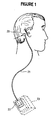
- Figure 1 illustrates a supersonic hearing assist device which includes a transducer 20, a cable 21, and a tuning circuit 22 which is mounted within an electronic housing 23.
- the transducer is held up against the mastoid process of the temporal bone.
- the transducer can also be applied to other surfaces of the human body, for example, the wall of the ear canal, the middle of the human forehead, the human tooth, human clavicle, human spine, or other bones.
- the housing 23 includes a microphone for receiving sounds in the auditory frequency range and a device for amplifying and converting the frequencies to the supersonic range and for applying electrical signals to the transducer.
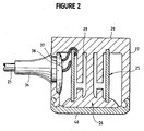
- the transducer 20 is best described as a piezoelectric longitudinal vibrator and includes a central piezoelectric ceramic tube 25, a radiating surface or head mass 26, and an inertial or tail mass 27.
- the radiating surface and inertial mass are tied together by a tensioning rod 28 to keep the assembly from self destructing as a result of large displacements of the radiating surface.
- the inertial mass is also the housing assembly for the device.
- the inertial mass 27 can be formed from separate components which include a generally cylindrical housing 30, a back plate 31, and a nut 32.
- the housing 30 represents the front half of the transducer inertial mass or housing assembly. It includes an outer wall with a recess 34 for mating with the back plate 31. One side is provided with a half capture ring 35 for clamping onto the cable strain relief 36 ( Figure 2). At this point, the inside diameter of the housing is carved out to provide a channel for transducer wiring 37 and 38 ( Figure 2). On the outer front surface, the housing features a retention ring 39 for a silicone rubber cap 40 ( Figure 2) on the transducer face. On the inner front diameter, the housing wall is tapered outward to allow for the taper on the head mass 26 ( Figure 2).
- the back plate 31 features an internal slotted ring 42 for the capture and adhesion of the piezoelectric ceramic tube 25 ( Figure 2).
- the electrical lead 37 for the inner electrode of the ceramic tube is passed through this hole around the bottom of the ceramic to the inner electrode.
- On this same side of the back plate there is a matching hole 44 for the cable and strain relief 36 ( Figure 2).
- the inner wall of the back plate is further recessed in this area to allow for the placement of the electrical leads 37 and 38 ( Figure 2) to the inner and outer cylindrical electrodes of the ceramic tube.
- the front of the back plate features an inner wall cut back 45 to provide for a cylindrical lap joint with the housing.
- the nut 32 comprises typically four complete 4-40 threads 46 to tension the tensioning rod 28 (Figure 2).
- Two holes 47 on the back surface of the nut allow for the pins of a spanner wrench to tighten the nut.
- the back walls of the nut and back plate 31 are in the same plane.
- the nut also features an inner column 48 of metal, with an outer diameter to fit inside the ceramic tube 25 (Figure 2) and an inner diameter to not interfere with the tensioning rod 28 ( Figure 2).
- the length of this column is designed to be as long as possible without interfering with the radiating surface or head mass 26.
- the entire housing assembly is designed for the maximum volume of metal to achieve the greatest inertial mass. If the radiating mass and the inertial mass have the same mass, then the acoustic radiation will be divided equally between the front and back surfaces. As more mass is accumulated in the tail mass, a greater fraction of displacement will occur at the head mass. For a tail mass to head mass ratio of 10:1, for example, the emission from the tail mass is 20 dB down from the emission from the head mass. The emission ratio is thus in competition with the physical size of the device.
- the material of the housing assembly is selected to be a hardened stainless steel, typically a 416 stainless steel hardened to Rockwell 35, to assure for minimal distortion of the transducer assembly. Any distortion of the housing assembly will be converted to heat, in addition to reducing the effective head mass emission.
- the overall physical size of the housing assembly is typically 0.75 inches in diameter, and 0.72 inches in length.
- the nominal mass of the collective housing assembly is typically 26 grams.
- the housing 30 and back plate 31 are typically bonded with a penetrating epoxy.
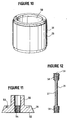
- the ceramic tube 25 ( Figure 2) for the transducer assembly, as illustrated in Figure 10, comprises a piezoelectric ceramic material with electrodes 50 and 51 on the inner and outer surfaces of the cylindrical wall, respectively. Both electrodes are etched back on both ends of the ceramic a small distance to allow for capture of the ceramic in the ceramic capture ring 42 of the back plate 31 and head mass 26 without resulting in a short circuit.
- the ceramic When a voltage is applied across the electrodes of the ceramic, the ceramic either expands or contracts in thickness. This motion is inconsequential to the operation of the device. At the same time, the ceramic also contracts or expands in length and circumference. The expansion and contraction in length is what drives the head mass in a longitudinal vibration.
- the ceramic material is selected from the family of lead zirconate titanate (PZT), more specifically from the PZT-4 and PZT-8 ceramics. These particular ceramic materials are selected for their especially low value of dissipation factor or loss tangent, the parameter which relates to the tendency of the ceramic to generate heat as a result of large applied electric fields. The low heat abilities of these materials markedly overshadow the attendant reduced displacement.
- PZT lead zirconate titanate
- the capacitances of typical ceramics are in the 7.5 nano Farad range.
- the ceramic tube 25 is bonded to the back plate 31 and to the head mass 26 with an epoxy, typically with a penetrating epoxy.
- the piezoelectric ceramic tube might be replaced in the electromechanical vibrator by a piezoelectric ceramic stack.
- the piezoelectric ceramic stack comprises a stack of ceramic washers of alternating piezoelectric polarity. Electrodes are wired in common, alternating along the length of the stack. The exchange of the ceramic stack for the ceramic tube will necessitate a minor redesign of the mating surfaces on the back plate and the head mass, the major difference being perhaps a greater wall thickness for the piezoelectric stack. This difference in wall thickness will affect the resonant frequency of the device.
- the radiating head mass 26 is depicted in cross section in Figure 11.
- the nominal diameter of the head mass is 0.50 inches.
- the head mass features a cylindrical groove 53 for ceramic retention, in the same manner as the back plate 31.
- the head mass also features at least four complete 4-40 threads 54 for the attachment of the tensioning rod 28 ( Figure 2).
- the face 55 of the head mass makes contact with the silicone cap 40 ( Figure 2). If the silicone cap material is clear, a fine machined surface is preferred.
- the head mass also features a cylindrical mass 55 of material extending toward the rear of the transducer, with an outer diameter less than the inner wall of the ceramic tube and an inner diameter which does not interfere with the tension rod. This extra material acts to stiffen the head mass and also to adjust the device resonant frequency.
- Head masses are in the mass range from typically 0.5 grams to 7 grams, more typically in the range from 1.5 to 4 grams. Ideally, the mass of the head mass would be approximately 10 times less than the mass of the housing assembly.
- the head mass is typically fabricated from common metals, more typically from hardened metals, and preferably from hardened stainless steel, typically 416 stainless steel hardened to Rockwell 35. Alternatively, brass may be used for increased mass (lower frequency) or aluminum for decreased mass (higher frequency).
- the tensioning rod 28 is depicted in Figure 12.
- the rod features a thinned middle section 57 and at least four complete 4-40 threads 58 on each end.
- One end additionally features a slot 59 for a small screw driver.
- the rod is adhesively bonded into the head mass 26 with a penetrating epoxy such that the face of the head mass and the flat end of the rod are flush.
- the slotted end 59 of the rod is attached to the nut 32.
- the screw driver slot allows for the tensioning of the rod by the nut without exerting a torque on the nut which might twist the rod or exert a rotational shear on the ceramic.
- the tensioning rod is typically fabricated from hardened stainless steel, typically 416 stainless steel hardened to Rockwell 35. A typical mass for the rod is 0.35 grams.
- the middle section 57 of the rod has a diameter at approximately 0.060 inches over a length of 0.49 inches.
- the transducer can be effectively operated without a cover over the head mass 26.
- a cap 40 ( Figure 2) is placed over the face of the transducer.
- This cap is typically from the family of materials referred to as silicone rubbers, more typically cast-in-place silicone rubber.
- a preferred material is a CF2-2186 silicone rubber manufactured by NuSil Technology, Inc.
- a silicone primer is typically used.
- a typical resonant frequency for the transducer with the above mentioned materials, dimensions, and masses is on the order of 28 kHz.
- the resonant frequency will go up.
- simply reducing the mass of the head mass will increase the resonant frequency of the device.
- the subject transducer has been implemented with different head masses ranging from 0.6 to 6.4 grams, with subsequent resonant frequencies from 22 to 39 kHz.
- the performance of the transducers is best assessed with the experimental configuration in Figure 13.
- a signal generator 61 is required to sweep a continuous wave signal across the band of operation of the transducer 20.
- the power amplifier 62 allows operation at any power level, to assess transducer response as a function of input level.
- the transducer is typically mounted in a vise, to best approximate the infinite inertial mass configuration.
- the transducer head mass is also fitted with a "water equivalent mass" 63 to compensate the measurements for the absence of the water (or tissue mass) medium which the transducer is designed to vibrate. The vibration of the head mass and the water equivalent mass is best measured with non-contacting optical displacement meter 64.
- the displacement of the head mass can be measured without the use of a water equivalent mass, in water, with a laser interferometer.
- the input signal to the transducer and the output of the calibrated displacement meter are passed to a scope 65 and/or spectrum analyser 66 which provides a hard copy output 67.
- the circuit also includes an attenuator 68.
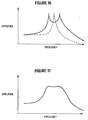
- a typical spectral response from a transducer using the above test method is illustrated in Figure 14, for a constant amplitude input signal.
- the spectrum typically features a low level flat response at low frequencies, typically within a few dB of the value predicted by Equation 1 above.
- the resonant frequency is typically predicted by Equation 3 above, and the resonant amplitude is typically 35 to 40 dB above the "DC" static level.
- the band width at typically 6dB down observed from an untuned transducer as seen in Figure 14 is unacceptable, typically in the 1 kHz range.
- the band width can be significantly enhanced by implementation of a tuning circuit.
- FIG. 15 depicts the equivalent circuit for the transducer with a tuning circuit.
- the system is operated in a push/pull mode (common mode).
- Each leg of the tuning circuit is identical.
- the piezoelectric ceramic and transducer components can be modeled as a parallel R, L, C, and C o circuit, where the L and C define the electromechanical resonant frequency of the transducer, the R reflects the sink for conversion of electrical energy to mechanical energy, and C o the clamped "DC" capacitance of the ceramic.
- the spectrum of Figure 14 is split into that depicted in Figure 16. If the inductive values are low, the resonance is at a higher frequency, and the higher frequency peak increases with respect to the lower frequency peak, and vice versa. While the band width is substantially increased, the remaining sharp spikes in the spectrum would result in too great a variation in amplitude for the human subject. Placing resistors across the inductors has the effect of lowering the spikes in the spectrum, to achieve the desired spectral response as depicted in Figure 17. Increasing the values of the resistors will increase the amplitude of the spikes in the spectrum while reducing the values of the resistors will round off the entire spectrum, and additionally will consume greater power from the electronic drive system.
- Parallel capacitors in the tuning circuit allow for fine tuning of the inductors to optimally match the tuned resonance with the device electromechanical resonance.
- the variation of the two peaks can typically be held to less than 2dB while the peak to null amplitude difference at the top of the spectrum can be held to less than 3 dB. Band widths can easily exceed 6 kHz.
- the inductive values of the tuning circuit are typically 2.4 milli Henry and the resistances typically have values of 3000 ohms.
- the transducer cable 21 ( Figure 2) is typically a shielded twisted pair cable, with the twisted leads 37 and 38 providing common mode power to the transducer and the shield electrically connecting the transducer housing assembly and head mass to the system ground.
- variations in transducer frequency band can be achieved by changing the mass of the head mass 26. These variations will affect the value of the tuning inductor and resistor.
- the inductor values are directly predictable by the resonant frequency and the ceramic capacitance.
- the resistive values are generally in the range from 1000 ohms to 10,000 ohms, the value being selected in final test to achieve the requisite flatness across the top of the transducer spectrum.
- the tensioning rod 28 through the middle of the transducer must have sufficient tension such that the head mass 26 is under compressive bias at all times, for any amplitude of emission, for any frequency.
- Newton's equation predicts the force on a mass undergoing oscillations at a specific frequency at a certain amplitude.
- the mass comprises the total mass of the head mass plus one third of the masses of the ceramic and the rod.
- the frequency under consideration corresponds to the highest frequency peak of the transducer spectrum.
- the transducer can also be used in a supersonic bone conduction hearing aid as described in Lenhardt U.S. Patent No. 4,982,434, in the diagnosis and treatment of tinnitus as described in U.S. patent application entitled "Tinnitus Masking Using Ultrasonic Signals,” Serial No. 08/264,527, filed June 23, 1994, and in other procedures and applications which utilize ultrasonic signals.
- the invention can also be used to test a patient's vestibular function on the theory that if a patient cannot hear using the bone conduction device described herein, which we believe is mediated by the vestibular system, then there is a vestibular problem.
- the invention can also be used to treat vestibular function disorders say, for example, as a "vestibular masker" to lessen or alleviate motion sickness.
Abstract
A device for diagnosing and treating hearing
disorders including a supersonic transducer which has
a resonance frequency in the supersonic range. The
transducer includes a piezoelectric ceramic tube
which is compressed between a head mass and an
inertial mass. A tensioning rod extends between the
masses and is threadedly engaged with a nut which
tensions the rod to adjust the compression on the
ceramic tube. A tuning circuit can be used to
increase the band width at resonance.
Description
This invention relates to a device for
diagnosing and treating hearing disorders. More
particularly, the invention relates to a device for
delivering auditory sensations to the profoundly deaf
and others. The device is particularly suitable for
supersonic bone conduction hearing devices, diagnosis
and treatment of tinnitus, diagnosis and treatment of
vestibular function conditions, echo location, and
determination of individual sensitivity to ultrasonic
signals. The ultrasonic frequency range is about 20
kHz to about 108 kHz or higher.
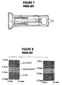
Early prior art starts with the use of
significantly large and bulky accelerometer devices.
A next generation of devices were bimorphs from
Blatec, as illustrated in Figure 3. These devices
were higher frequency acoustic generators/ sensors
reportedly used to sense the presence or absence of
materials on an assembly line. The devices consisted
of a thin piece of piezoelectric ceramic, typically
0.040 inches thick, bonded directly onto a thin sheet
of aluminum, typically 0.020 inches thick. When a
voltage is placed across the electrodes of the
ceramic, the material either shrinks or expands in the
direction of the electric field, depending on the
polarity of the device. This movement of the ceramic
has no beneficial output with regard to the hearing
assist devices. But in response to the same electric
field, the ceramic also expands or shrinks in the
lateral direction, perpendicular to the electric
field. However, since the physical size of the
ceramic is constrained by virtue of its lamination to
the aluminum sheet, the ceramic will bow the
lamination into an either concave or convex form,
depending on the polarity. Application of an
alternating voltage will then generate vibrations at
the frequency of the input signal.
The devices of Figure 3 did not have a
strong natural resonance in the 20 to 40 kHz region as
required for supersonic hearing devices, nor did they
have the required band width. Further, under the
drive conditions required for supersonic hearing
devices, these devices very rapidly either
delaminated, broke the ceramic, broke the electrical
connections to the ceramic electrodes, or heated up
and depolarized rendering the ceramic inert.
Another generation of devices was available
from Motorola, based on their development and
manufacturing of piezo tweeters, as illustrated in
Figure 4. The devices were redesigned to place a
strong natural resonance in the supersonic frequency
range of interest, but they still lacked the desired
band width. The basic concept of a bimorph, however,
was the same, with exactly the same consequences.
Yet a further generation of devices was
developed by ECHO Ultrasound. ECHO felt constrained
to continue the development of Motorola, and did
succeed in opening up the band width. Yet, the basic
concept of a bimorph failed. These devices generated
excessive amounts of heat (severe burn potential) and
failed rapidly, typically within seconds of operation.
As a result of naval sonar during and after
World War II, power ultrasonics began to be developed.
More relevant to the subject at hand was the field of
piezoceramic longitudinal vibrators, as shown in
Figure 5, from the book of Leon W. Camp, "Underwater
Acoustics", Wiley-Interscience, 1970. Indeed, Camp
writes in his book:
An even earlier work, F. Rosenthal, and V.
D. Mikuteit, (1959), IRE National Convention Record 7,
Part 6, 252, and subsequently published as "Vibrations
of Ferroelectric Transducer Elements Loaded by Masses
and Acoustic Radiation" in IRE Transactions on
Ultrasonics Engineering, 2/1960, pp. 12-15 describes a
mass loaded composite transducer featuring a ceramic
tube and a bolt for compressive bias, as seen in
Figure 6. Rosenthal and Mikuteit go further to
predict the operational resonant frequency of the
device, as a function of the masses, the physical size
of the ceramic tube, and the elastic constant of the
ceramic. Of note, the resonant frequency is not
dependent on the length of the device, as a function
of resonant wavelength. The author's expression for
the resonant frequency is simplified for the case of
large masses. These same results are also published
in W. P. Mason, "Physical Acoustics, Principles and
Methods", Vol. 1, Part A, Academic Press, 1964.
In a companion work by R. S. Woollett, IRE
International Convention Record 10, Part 6, p. 90,
1962, the case of air backing and fluid loading is
addressed. This situation is the operational
environment of the inventive device, where the fluid
medium is the human body.
An alternative form of the above with a
ceramic stack as compared to a ceramic tube is
frequently used and also heavily described in the
literature. A more recent paper by A. C. Tims, D. L.
Carson, and G. W. Benthien, "Piezoelectric Ceramic
Reproducibility (for 33 Mode Transducer Application),
Proceedings of the 6th IEEE International Symposium on
Applications of Ferroelectrics, Lehigh U., Bethlehem,
PA, pp. 6245-627, 6/8-11/ 1986, clearly depicts the
use of a stack as compared to the tube, as seen in
Figure 7.
The concept of an active component between a
radiating mass and an inertial mass is still of
significant interest in the transducer community, as
manifested by the recent work of J. Lan, M. J.
Simoneau, and S. G. Boucher, "Development of an
Efficient Transducer Design Tool: Complete Finite
Element Modeling of Transducer Performance Parameters
on a PC", SPIE Vol. 1733, 1992, pp. 57-71. As seen in
Figure 8, they partition the components into
incrementally small segments, individually and
iteratively note the displacements to each segment,
and predict overall device performance.
Although not easily observable from the
literature, naval sonar has been utilizing these
concepts for many years.
On the subject of tuning devices, virtually
every textbook on transducers includes a section on
tuning to impedance match or to broaden the bandwidth.
No effort is made herewith to document the totality of
electrical matching circuits.
The invention provides a transducer which
has a resonant frequency in the supersonic range. A
tuning circuit can be used to increase the band width
at resonance. The transducer is particularly suitable
for use in supersonic bone conduction hearing devices,
diagnosis and treatment of tinnitus, echo location,
diagnosis and treatment of vestibular function
conditions, and other applications and procedures
which use supersonic signals.
The transducer includes a piezoelectric
ceramic tube which is compressed between a head mass
and an inertial mass. A tensioning rod extends
between the masses and is threadedly engaged with a
nut which tensions the rod to adjust the compression
on the ceramic tube.
The invention will be explained in
conjunction with an illustrative embodiment shown in
the accompanying drawings, in which --
Figure 1 illustrates a supersonic hearing
assist device which includes a transducer 20, a cable
21, and a tuning circuit 22 which is mounted within an
electronic housing 23. The transducer is held up
against the mastoid process of the temporal bone. The
transducer can also be applied to other surfaces of
the human body, for example, the wall of the ear
canal, the middle of the human forehead, the human
tooth, human clavicle, human spine, or other bones.
For a complete description of a supersonic bone
conduction hearing aid and its method of use, see
Lenhardt et al U.S. Patent No. 4,982,434 which is
incorporated herein by reference. In general the
housing 23 includes a microphone for receiving sounds
in the auditory frequency range and a device for
amplifying and converting the frequencies to the
supersonic range and for applying electrical signals
to the transducer.
Referring to Figure 2, the transducer 20 is
best described as a piezoelectric longitudinal
vibrator and includes a central piezoelectric ceramic
tube 25, a radiating surface or head mass 26, and an
inertial or tail mass 27. The radiating surface and
inertial mass are tied together by a tensioning rod 28
to keep the assembly from self destructing as a result
of large displacements of the radiating surface. The
inertial mass is also the housing assembly for the
device.
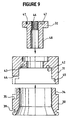
Referring to Figure 9, the inertial mass 27
can be formed from separate components which include a
generally cylindrical housing 30, a back plate 31, and
a nut 32.
The housing 30 represents the front half of
the transducer inertial mass or housing assembly. It
includes an outer wall with a recess 34 for mating
with the back plate 31. One side is provided with a
half capture ring 35 for clamping onto the cable
strain relief 36 (Figure 2). At this point, the
inside diameter of the housing is carved out to
provide a channel for transducer wiring 37 and 38
(Figure 2). On the outer front surface, the housing
features a retention ring 39 for a silicone rubber cap
40 (Figure 2) on the transducer face. On the inner
front diameter, the housing wall is tapered outward to
allow for the taper on the head mass 26 (Figure 2).
The back plate 31 features an internal
slotted ring 42 for the capture and adhesion of the
piezoelectric ceramic tube 25 (Figure 2). On one side
of the back plate at the site of the hole for the
cable and strain relief 36 (Figure 2), there is a
small hole 43 with a diameter approximately three
times the nominal width of the slot 42. The
electrical lead 37 for the inner electrode of the
ceramic tube is passed through this hole around the
bottom of the ceramic to the inner electrode. On this
same side of the back plate, there is a matching hole
44 for the cable and strain relief 36 (Figure 2). The
inner wall of the back plate is further recessed in
this area to allow for the placement of the electrical
leads 37 and 38 (Figure 2) to the inner and outer
cylindrical electrodes of the ceramic tube. The front
of the back plate features an inner wall cut back 45
to provide for a cylindrical lap joint with the
housing.
The nut 32 comprises typically four complete
4-40 threads 46 to tension the tensioning rod 28
(Figure 2). Two holes 47 on the back surface of the
nut allow for the pins of a spanner wrench to tighten
the nut. The back walls of the nut and back plate 31
are in the same plane. The nut also features an inner
column 48 of metal, with an outer diameter to fit
inside the ceramic tube 25 (Figure 2) and an inner
diameter to not interfere with the tensioning rod 28
(Figure 2). The length of this column is designed to
be as long as possible without interfering with the
radiating surface or head mass 26.
In general, the entire housing assembly is
designed for the maximum volume of metal to achieve
the greatest inertial mass. If the radiating mass and
the inertial mass have the same mass, then the
acoustic radiation will be divided equally between the
front and back surfaces. As more mass is accumulated
in the tail mass, a greater fraction of displacement
will occur at the head mass. For a tail mass to head
mass ratio of 10:1, for example, the emission from the
tail mass is 20 dB down from the emission from the
head mass. The emission ratio is thus in competition
with the physical size of the device.
The material of the housing assembly is
selected to be a hardened stainless steel, typically a
416 stainless steel hardened to Rockwell 35, to assure
for minimal distortion of the transducer assembly.
Any distortion of the housing assembly will be
converted to heat, in addition to reducing the
effective head mass emission.
The overall physical size of the housing
assembly is typically 0.75 inches in diameter, and
0.72 inches in length. The nominal mass of the
collective housing assembly is typically 26 grams.
The housing 30 and back plate 31 are
typically bonded with a penetrating epoxy.
The ceramic tube 25 (Figure 2) for the
transducer assembly, as illustrated in Figure 10,
comprises a piezoelectric ceramic material with
electrodes 50 and 51 on the inner and outer surfaces
of the cylindrical wall, respectively. Both
electrodes are etched back on both ends of the ceramic
a small distance to allow for capture of the ceramic
in the ceramic capture ring 42 of the back plate 31
and head mass 26 without resulting in a short circuit.
When a voltage is applied across the
electrodes of the ceramic, the ceramic either expands
or contracts in thickness. This motion is
inconsequential to the operation of the device. At
the same time, the ceramic also contracts or expands
in length and circumference. The expansion and
contraction in length is what drives the head mass in
a longitudinal vibration.
The ceramic material is selected from the
family of lead zirconate titanate (PZT), more
specifically from the PZT-4 and PZT-8 ceramics. These
particular ceramic materials are selected for their
especially low value of dissipation factor or loss
tangent, the parameter which relates to the tendency
of the ceramic to generate heat as a result of large
applied electric fields. The low heat abilities of
these materials markedly overshadow the attendant
reduced displacement.
The static "DC" longitudinal zero to peak
displacement D of the cylindrical tube ceramic is
given by the expression:
D = d31 V L / thk
where
The above expression suggests that increased
emission might be obtained by lengthening the ceramic
and making the wall thinner. A lengthened cylinder
competes with the accepted physical size of the
device. Thinner walls require less applied voltage as
the ceramics are limited by the maximum electric
fields, not applied voltage. However, no benefit
would be achieved.
The capacitances of typical ceramics are in
the 7.5 nano Farad range.
The ceramic tube 25 is bonded to the back
plate 31 and to the head mass 26 with an epoxy,
typically with a penetrating epoxy.
Alternatively, the piezoelectric ceramic
tube might be replaced in the electromechanical
vibrator by a piezoelectric ceramic stack. The
piezoelectric ceramic stack comprises a stack of
ceramic washers of alternating piezoelectric polarity.
Electrodes are wired in common, alternating along the
length of the stack. The exchange of the ceramic
stack for the ceramic tube will necessitate a minor
redesign of the mating surfaces on the back plate and
the head mass, the major difference being perhaps a
greater wall thickness for the piezoelectric stack.
This difference in wall thickness will affect the
resonant frequency of the device.
The radiating head mass 26 is depicted in
cross section in Figure 11. The nominal diameter of
the head mass is 0.50 inches. The head mass features
a cylindrical groove 53 for ceramic retention, in the
same manner as the back plate 31. The head mass also
features at least four complete 4-40 threads 54 for
the attachment of the tensioning rod 28 (Figure 2).
The face 55 of the head mass makes contact with the
silicone cap 40 (Figure 2). If the silicone cap
material is clear, a fine machined surface is
preferred. The head mass also features a cylindrical
mass 55 of material extending toward the rear of the
transducer, with an outer diameter less than the inner
wall of the ceramic tube and an inner diameter which
does not interfere with the tension rod. This extra
material acts to stiffen the head mass and also to
adjust the device resonant frequency.
Head masses are in the mass range from
typically 0.5 grams to 7 grams, more typically in the
range from 1.5 to 4 grams. Ideally, the mass of the
head mass would be approximately 10 times less than
the mass of the housing assembly. The head mass is
typically fabricated from common metals, more
typically from hardened metals, and preferably from
hardened stainless steel, typically 416 stainless
steel hardened to Rockwell 35. Alternatively, brass
may be used for increased mass (lower frequency) or
aluminum for decreased mass (higher frequency).
The tensioning rod 28 is depicted in Figure
12. The rod features a thinned middle section 57 and
at least four complete 4-40 threads 58 on each end.
One end additionally features a slot 59 for a small
screw driver. The rod is adhesively bonded into the
head mass 26 with a penetrating epoxy such that the
face of the head mass and the flat end of the rod are
flush. During transducer assembly, the slotted end 59
of the rod is attached to the nut 32. The screw
driver slot allows for the tensioning of the rod by
the nut without exerting a torque on the nut which
might twist the rod or exert a rotational shear on the
ceramic.
The tensioning rod is typically fabricated
from hardened stainless steel, typically 416 stainless
steel hardened to Rockwell 35. A typical mass for the
rod is 0.35 grams. The middle section 57 of the rod
has a diameter at approximately 0.060 inches over a
length of 0.49 inches.
The transducer can be effectively operated
without a cover over the head mass 26. However, to
protect the internal ceramic cylinder 26, a cap 40
(Figure 2) is placed over the face of the transducer.
This cap is typically from the family of materials
referred to as silicone rubbers, more typically cast-in-place
silicone rubber. A preferred material is a
CF2-2186 silicone rubber manufactured by NuSil
Technology, Inc. To assure excellent adhesion of the
rubber to the head mass and housing, a silicone primer
is typically used.
Rosenthal and Mikuteit suggested the
resonant frequency of their device as:
ω = { 2 A / M s11 E L} 1/2
where
If the assumption of an infinite inertial or
tail mass can be made, the resonant frequency of the
current device can be approximated by the expression
ω = {A / (M + Mc / 3 + Mr / 3) s11 E L} 1/2
where
A typical resonant frequency for the
transducer with the above mentioned materials,
dimensions, and masses is on the order of 28 kHz. Of
note in the above expression, if the ceramic is made
stiffer by decreasing the length or increasing the
cross sectional area, the resonant frequency will go
up. Also and more easily implemented, simply reducing
the mass of the head mass will increase the resonant
frequency of the device. Indeed, the subject
transducer has been implemented with different head
masses ranging from 0.6 to 6.4 grams, with subsequent
resonant frequencies from 22 to 39 kHz. This broad
range of frequency opportunities is especially useful
in adjusting the transducer to match the particular
deficit of the human subject, as discussed in greater
detail in co-pending United States patent application
entitled "Apparatus and Method for Determining
Individual Sensitivity to Ultrasonic Signals," filed
of even date herewith. Larger head masses may require
a volume expansion of the device. This includes
lengthening the housing, the tensioning rod, and the
head mass itself.
The performance of the transducers is best
assessed with the experimental configuration in Figure
13. A signal generator 61 is required to sweep a
continuous wave signal across the band of operation of
the transducer 20. The power amplifier 62 allows
operation at any power level, to assess transducer
response as a function of input level. The transducer
is typically mounted in a vise, to best approximate
the infinite inertial mass configuration. The
transducer head mass is also fitted with a "water
equivalent mass" 63 to compensate the measurements for
the absence of the water (or tissue mass) medium which
the transducer is designed to vibrate. The vibration
of the head mass and the water equivalent mass is best
measured with non-contacting optical displacement
meter 64. (Alternatively, the displacement of the
head mass can be measured without the use of a water
equivalent mass, in water, with a laser
interferometer). The input signal to the transducer
and the output of the calibrated displacement meter
are passed to a scope 65 and/or spectrum analyser 66
which provides a hard copy output 67. The circuit
also includes an attenuator 68.
A typical spectral response from a
transducer using the above test method is illustrated
in Figure 14, for a constant amplitude input signal.
The spectrum typically features a low level flat
response at low frequencies, typically within a few dB
of the value predicted by Equation 1 above. The
resonant frequency is typically predicted by Equation
3 above, and the resonant amplitude is typically 35 to
40 dB above the "DC" static level. At high
frequencies, the signal strength drops off rapidly.
Of note, the band width at typically 6dB down observed
from an untuned transducer as seen in Figure 14 is
unacceptable, typically in the 1 kHz range. The band
width can be significantly enhanced by implementation
of a tuning circuit.
Figure 15 depicts the equivalent circuit for
the transducer with a tuning circuit. The system is
operated in a push/pull mode (common mode). Each leg
of the tuning circuit is identical. Within the
transducer, the piezoelectric ceramic and transducer
components can be modeled as a parallel R, L, C, and
Co circuit, where the L and C define the
electromechanical resonant frequency of the
transducer, the R reflects the sink for conversion of
electrical energy to mechanical energy, and Co the
clamped "DC" capacitance of the ceramic.
When the combined value of the tuning
inductors is such as to create a resonance with Co at
the same frequency as the electromechnical resonance,
the spectrum of Figure 14 is split into that depicted
in Figure 16. If the inductive values are low, the
resonance is at a higher frequency, and the higher
frequency peak increases with respect to the lower
frequency peak, and vice versa. While the band width
is substantially increased, the remaining sharp spikes
in the spectrum would result in too great a variation
in amplitude for the human subject. Placing resistors
across the inductors has the effect of lowering the
spikes in the spectrum, to achieve the desired
spectral response as depicted in Figure 17.
Increasing the values of the resistors will increase
the amplitude of the spikes in the spectrum while
reducing the values of the resistors will round off
the entire spectrum, and additionally will consume
greater power from the electronic drive system.
Parallel capacitors in the tuning circuit
allow for fine tuning of the inductors to optimally
match the tuned resonance with the device
electromechanical resonance.
The variation of the two peaks can typically
be held to less than 2dB while the peak to null
amplitude difference at the top of the spectrum can be
held to less than 3 dB. Band widths can easily exceed
6 kHz.
For a transducer operating at typically 28
kHz, the inductive values of the tuning circuit are
typically 2.4 milli Henry and the resistances
typically have values of 3000 ohms.
The transducer cable 21 (Figure 2) is
typically a shielded twisted pair cable, with the
twisted leads 37 and 38 providing common mode power to
the transducer and the shield electrically connecting
the transducer housing assembly and head mass to the
system ground.
As stated above, variations in transducer
frequency band can be achieved by changing the mass of
the head mass 26. These variations will affect the
value of the tuning inductor and resistor. The
inductor values are directly predictable by the
resonant frequency and the ceramic capacitance. The
resistive values are generally in the range from 1000
ohms to 10,000 ohms, the value being selected in final
test to achieve the requisite flatness across the top
of the transducer spectrum.
The tensioning rod 28 through the middle of
the transducer must have sufficient tension such that
the head mass 26 is under compressive bias at all
times, for any amplitude of emission, for any
frequency. Newton's equation predicts the force on a
mass undergoing oscillations at a specific frequency
at a certain amplitude. In this case, the mass
comprises the total mass of the head mass plus one
third of the masses of the ceramic and the rod. The
frequency under consideration corresponds to the
highest frequency peak of the transducer spectrum.
When a piezoelectric ceramic is compressed
under static pressure, the material will develop a
voltage across the electrodes. For any ceramic, a
charge corresponding to the maximum excursion of the
head mass can be calculated. The ceramic leads are
attached to an electrometer and the tensioning rod is
torqued until the specified charge has developed plus
a margin.
The transducer can also be used in a
supersonic bone conduction hearing aid as described in
Lenhardt U.S. Patent No. 4,982,434, in the diagnosis
and treatment of tinnitus as described in U.S. patent
application entitled "Tinnitus Masking Using
Ultrasonic Signals," Serial No. 08/264,527, filed June
23, 1994, and in other procedures and applications
which utilize ultrasonic signals.
The invention can also be used to test a
patient's vestibular function on the theory that if a
patient cannot hear using the bone conduction device
described herein, which we believe is mediated by the
vestibular system, then there is a vestibular problem.
The invention can also be used to treat vestibular
function disorders say, for example, as a "vestibular
masker" to lessen or alleviate motion sickness.
While in the foregoing specification a
detailed description of specific embodiments of the
invention were set forth for the purpose of
illustration, it will be understood that many of the
details herein given can be varied considerably by
those skilled in the art without departing from the
spirit and scope of the invention.
Claims (28)
- A device for supersonic bone conduction hearing in human subjects for allowing some level of auditory sensation comprising:means for receiving generated signals in the supersonic range,an electromechanical transducer assembly for receiving said signals in the supersonic range and for providing a vibratory output, the transducer including an inertial mass, a vibrating head mass, a piezoelectric ceramic tube between the inertial mass and head mass, and a tensioning rod connected to the head mass and the inertial mass and extending through the ceramic tube, the tensioning rod exerting a compressive force on the ceramic tube, the transducer having a resonant frequency within the range of about 20 kHz to 108 kHz, andtuning means for broadening the frequency response of the electromechanical transducer assembly.
- The device of claim 1 in which the resonant frequency is within the range of about 20 kHz to 108 kHz, more preferably in the range from 20 to 40 kHz.
- The device of claim 1 in which the inertial mass includes a housing portion which substantially surrounds the ceramic tube and a cylindrical portion which extends inside of the ceramic tube.
- The device of claim 3 in which the head mass includes a cylindrical portion which extends inside of the ceramic tube.
- The device of claim 3 in which the inertial mass includes a nut portion which is threadedly engaged with the tensioning rod.
- The device of claim 5 in which the nut portion of the inertial mass is rotatably mounted on the remainder of the inertial mass.
- The device of claim 1 in which the inertial mass and head mass are formed from metal selected from the class of steel, bronze, and aluminum.
- The device of claim 7 in which the tensioning rod is formed from metal selected from the class of steel, bronze, and aluminum.
- The device of claim 1 in which the mass of the head mass is within the range of 0.5 to 7 grams.
- The device of claim 9 in which the mass of the inertial mass is approximately 10 times the mass of the head mass.
- The device of claim 9 in which the mass of the inertial mass is about 26 grams.
- The device of claim 1 in which the mass of the head mass is within the range of 1.5 to 4 grams.
- The device of claim 1 in which the tuning means comprises a tuning circuit having a pair of tuning inductors connected in parallel to the transducer, the ceramic tube having a clamped DC capacitance of Co, the combined value of the tuning inductors creating a resonance with Co at the same frequency as the electromechanical resonant frequency of the transducer.
- The device of claim 13 including a tuning resistor connected in parallel with each of the tuning inductors.
- The device of claim 1 including a rubber cap mounted on the head mass.
- A method for providing auditory sensation to humans in the supersonic range comprising the steps of:placing an electromechanical transducer against the human body, the transducer including an inertial mass, a head mass, a piezoelectric ceramic tube between the inertial mass and the head mass, a tensioning rod connected to the head mass and the inertial mass and extending through the ceramic tube, the tensioning rod exerting a compressive force on the ceramic tube, the transducer having a resonant frequency within the range of about 20 kHz to 108 kHz, and tuning means for broadening the frequency response of the transducer, andgenerating signals in the supersonic range and delivering said signals to the tuning means so that the transducer provides a vibratory output having a wide band frequency response in the supersonic range.
- The method of claim 16 in which the transducer is placed against the mastoid bone of the human skull.
- The method of claim 16 in which the transducer is placed against the wall of the human ear canal.
- The method of claim 16 in which the transducer is placed against the human forehead.
- The method of claim 16 in which the transducer is placed against the human tooth.
- The method of claim 16 in which the transducer is placed against the human clavicle.
- The method of claim 16 in which the transducer is placed against the human spine.
- The method of claim 16 in which the transducer is placed against human bones.
- A method of supersonic bone conduction for the diagnosis and treatment of tinnitus comprising the steps of:placing an electromechanical transducer against the human body, the transducer including an inertial mass, a head mass, a piezoelectric ceramic tube between the inertial mass and the head mass, a tensioning rod connected to the head mass and the inertial mass and extending through the ceramic tube, the tensioning rod exerting a compressive force on the ceramic tube, the transducer having a resonant frequency within the range of about 20 kHz to 108 kHz, and tuning means for broadening the frequency response of the transducer, andgenerating signals in the supersonic range and delivering said signals to the tuning means so that the transducer provides a vibratory output having a wide band frequency range in the supersonic range.
- A method of supersonic bone conduction for the diagnosis and treatment of vestibular function conditions comprising the steps of:placing an electromechanical transducer against the human body, the transducer including an inertial mass, a head mass, a piezoelectric ceramic tube between the inertial mass and the head mass, a tensioning rod connected to the head mass and the inertial mass and extending through the ceramic tube, the tensioning rod exerting a compressive force on the ceramic tube, the transducer having a resonant frequency within the range of about 20 kHz to 108 kHz, and tuning means for broadening the frequency response of the transducer, andgenerating signals in the supersonic range and delivering said signals to the tuning means so that the transducer provides a vibratory output having a wide band frequency response in the supersonic range.
- A method of supersonic bone conduction for echo location comprising the steps of:placing an electromechanical transducer against the human body, the transducer including an inertial mass, a head mass, a piezoelectric ceramic tube between the inertial mass and the head mass, a tensioning rod connected to the head mass and the inertial mass and extending through the ceramic tube, the tensioning rod exerting a compressive force on the ceramic tube, the transducer having a resonant frequency within the range of about 20 kHz to 108 kHz, and tuning means for broadening the frequency response of the transducer, andgenerating signals in the supersonic range and delivering said signals to the tuning means so that the transducer provides a vibratory output having a wide band frequency response in the supersonic range.
- A device for supersonic bone conduction hearing in human subjects for allowing some level of auditory sensation comprising:means for receiving generated signals in the supersonic range,an electromechanical transducer assembly for receiving said signals in the supersonic range and for providing a vibratory output, the transducer including an inertial mass, a vibrating head mass, a piezoelectric ceramic stack between the inertial mass and head mass, and a tensioning rod connected to the head mass and the inertial mass and extending through the ceramic stack, the tensioning rod exerting a compressive force on the ceramic stack, the transducer having a resonant frequency within the range of about 20 kHz to 108 kHz, andtuning means for broadening the frequency response of the electromechanical transducer assembly.
- A method of supersonic bone conduction for application to the profoundly deaf, for echo location, for diagnosis and treatment of tinnitus, and for diagnosis and treatment of vestibular function comprising the steps of:placing an electromechanical transducer against the human body, the transducer including an inertial mass, a head mass, a piezoelectric ceramic stack between the inertial mass and the head mass, a tensioning rod connected to the head mass and the inertial mass and extending through the ceramic stack, the tensioning rod exerting a compressive force on the ceramic stack, the transducer having a resonant frequency within the range of about 20 kHz to 108 kHz, and tuning means for broadening the frequency response of the transducer, andgenerating signals in the supersonic range and delivering said signals to the tuning means so that the transducer provides a vibratory output having a wide band frequency response in the supersonic range.
Applications Claiming Priority (2)
| Application Number | Priority Date | Filing Date | Title |
|---|---|---|---|
| US08/957,189 US6068590A (en) | 1997-10-24 | 1997-10-24 | Device for diagnosing and treating hearing disorders |
| US957189 | 1997-10-24 |
Publications (1)
| Publication Number | Publication Date |
|---|---|
| EP0912073A2 true EP0912073A2 (en) | 1999-04-28 |
Family
ID=25499197
Family Applications (1)
| Application Number | Title | Priority Date | Filing Date |
|---|---|---|---|
| EP98119499A Withdrawn EP0912073A2 (en) | 1997-10-24 | 1998-10-15 | Device for diagnosing and treating hearing disorders |
Country Status (4)
| Country | Link |
|---|---|
| US (1) | US6068590A (en) |
| EP (1) | EP0912073A2 (en) |
| JP (1) | JPH11262481A (en) |
| CA (1) | CA2248666A1 (en) |
Cited By (2)
| Publication number | Priority date | Publication date | Assignee | Title |
|---|---|---|---|---|
| WO2009121105A1 (en) * | 2008-03-31 | 2009-10-08 | Cochlear Limited | Piercing conducted bone conduction device |
| WO2012064247A1 (en) * | 2010-11-12 | 2012-05-18 | Osseofon Ab | Network for bone conduction transducers |
Families Citing this family (68)
| Publication number | Priority date | Publication date | Assignee | Title |
|---|---|---|---|---|
| US6394969B1 (en) * | 1998-10-14 | 2002-05-28 | Sound Techniques Systems Llc | Tinnitis masking and suppressor using pulsed ultrasound |
| DE19859171C2 (en) * | 1998-12-21 | 2000-11-09 | Implex Hear Tech Ag | Implantable hearing aid with tinnitus masker or noiser |
| US6372031B1 (en) * | 1999-08-03 | 2002-04-16 | Milliken & Company | Washable coloring compositions comprising low molecular-weight styrene-maleic anhydride copolymers |
| DE10041725B4 (en) * | 2000-08-25 | 2004-04-29 | Phonak Ag | Device for electromechanical stimulation and testing of the hearing |
| US7792089B2 (en) * | 2002-07-31 | 2010-09-07 | Cattron-Theimeg, Inc. | System and method for wireless remote control of locomotives |
| JP4617259B2 (en) * | 2002-12-06 | 2011-01-19 | エレクトロソニックス・メディカル・インコーポレイテッド | Ultrasonic detection of ear disorders |
| US20100069752A1 (en) * | 2002-12-06 | 2010-03-18 | Otosonics, Inc. | Ultrasonic detection of ear disorders |
| US7668325B2 (en) * | 2005-05-03 | 2010-02-23 | Earlens Corporation | Hearing system having an open chamber for housing components and reducing the occlusion effect |
| US8295523B2 (en) * | 2007-10-04 | 2012-10-23 | SoundBeam LLC | Energy delivery and microphone placement methods for improved comfort in an open canal hearing aid |
| US7867160B2 (en) * | 2004-10-12 | 2011-01-11 | Earlens Corporation | Systems and methods for photo-mechanical hearing transduction |
| US8014871B2 (en) * | 2006-01-09 | 2011-09-06 | Cochlear Limited | Implantable interferometer microphone |
| US20070261494A1 (en) * | 2006-04-28 | 2007-11-15 | Biomec, Inc. | Ultrasonic transducer devices and detection apparatus |
| US7796769B2 (en) * | 2006-05-30 | 2010-09-14 | Sonitus Medical, Inc. | Methods and apparatus for processing audio signals |
| US8291912B2 (en) * | 2006-08-22 | 2012-10-23 | Sonitus Medical, Inc. | Systems for manufacturing oral-based hearing aid appliances |
| US20080064993A1 (en) * | 2006-09-08 | 2008-03-13 | Sonitus Medical Inc. | Methods and apparatus for treating tinnitus |
| US8270638B2 (en) * | 2007-05-29 | 2012-09-18 | Sonitus Medical, Inc. | Systems and methods to provide communication, positioning and monitoring of user status |
| US20080304677A1 (en) * | 2007-06-08 | 2008-12-11 | Sonitus Medical Inc. | System and method for noise cancellation with motion tracking capability |
| US20090028352A1 (en) * | 2007-07-24 | 2009-01-29 | Petroff Michael L | Signal process for the derivation of improved dtm dynamic tinnitus mitigation sound |
| US20120235632A9 (en) * | 2007-08-20 | 2012-09-20 | Sonitus Medical, Inc. | Intra-oral charging systems and methods |
| US8433080B2 (en) * | 2007-08-22 | 2013-04-30 | Sonitus Medical, Inc. | Bone conduction hearing device with open-ear microphone |
| US8224013B2 (en) | 2007-08-27 | 2012-07-17 | Sonitus Medical, Inc. | Headset systems and methods |
| US7682303B2 (en) | 2007-10-02 | 2010-03-23 | Sonitus Medical, Inc. | Methods and apparatus for transmitting vibrations |
| EP2208367B1 (en) | 2007-10-12 | 2017-09-27 | Earlens Corporation | Multifunction system and method for integrated hearing and communiction with noise cancellation and feedback management |
| US20090105523A1 (en) * | 2007-10-18 | 2009-04-23 | Sonitus Medical, Inc. | Systems and methods for compliance monitoring |
| US8795172B2 (en) * | 2007-12-07 | 2014-08-05 | Sonitus Medical, Inc. | Systems and methods to provide two-way communications |
| US7974845B2 (en) | 2008-02-15 | 2011-07-05 | Sonitus Medical, Inc. | Stuttering treatment methods and apparatus |
| US8270637B2 (en) | 2008-02-15 | 2012-09-18 | Sonitus Medical, Inc. | Headset systems and methods |
| US8023676B2 (en) | 2008-03-03 | 2011-09-20 | Sonitus Medical, Inc. | Systems and methods to provide communication and monitoring of user status |
| US20090226020A1 (en) | 2008-03-04 | 2009-09-10 | Sonitus Medical, Inc. | Dental bone conduction hearing appliance |
| US8150075B2 (en) | 2008-03-04 | 2012-04-03 | Sonitus Medical, Inc. | Dental bone conduction hearing appliance |
| US20090270673A1 (en) * | 2008-04-25 | 2009-10-29 | Sonitus Medical, Inc. | Methods and systems for tinnitus treatment |
| US8396239B2 (en) | 2008-06-17 | 2013-03-12 | Earlens Corporation | Optical electro-mechanical hearing devices with combined power and signal architectures |
| EP2301261B1 (en) | 2008-06-17 | 2019-02-06 | Earlens Corporation | Optical electro-mechanical hearing devices with separate power and signal components |
| CN102138340B (en) | 2008-06-17 | 2014-10-08 | 依耳乐恩斯公司 | Optical electro-mechanical hearing devices with combined power and signal architectures |
| KR101717034B1 (en) | 2008-09-22 | 2017-03-15 | 이어렌즈 코포레이션 | Balanced armature devices and methods for hearing |
| CN102598712A (en) | 2009-06-05 | 2012-07-18 | 音束有限责任公司 | Optically coupled acoustic middle ear implant systems and methods |
| US9544700B2 (en) | 2009-06-15 | 2017-01-10 | Earlens Corporation | Optically coupled active ossicular replacement prosthesis |
| WO2010148345A2 (en) | 2009-06-18 | 2010-12-23 | SoundBeam LLC | Eardrum implantable devices for hearing systems and methods |
| US10286215B2 (en) | 2009-06-18 | 2019-05-14 | Earlens Corporation | Optically coupled cochlear implant systems and methods |
| CN102598715B (en) | 2009-06-22 | 2015-08-05 | 伊尔莱茵斯公司 | optical coupling bone conduction device, system and method |
| US10555100B2 (en) * | 2009-06-22 | 2020-02-04 | Earlens Corporation | Round window coupled hearing systems and methods |
| US8845705B2 (en) | 2009-06-24 | 2014-09-30 | Earlens Corporation | Optical cochlear stimulation devices and methods |
| US8715154B2 (en) | 2009-06-24 | 2014-05-06 | Earlens Corporation | Optically coupled cochlear actuator systems and methods |
| US8433082B2 (en) | 2009-10-02 | 2013-04-30 | Sonitus Medical, Inc. | Intraoral appliance for sound transmission via bone conduction |
| DK2656639T3 (en) | 2010-12-20 | 2020-06-29 | Earlens Corp | Anatomically adapted ear canal hearing aid |
| US20120300953A1 (en) | 2011-05-24 | 2012-11-29 | Herbert Mauch | Integrity evaluation system in an implantable hearing prosthesis |
| WO2013062949A1 (en) * | 2011-10-25 | 2013-05-02 | Martin Scientific, Llc | High-speed downhole sensor and telemetry network |
| CN103529565A (en) * | 2013-10-22 | 2014-01-22 | 西安康弘新材料科技有限公司 | Installation structure of piezoelectric ceramic bone conductive vibrators in glasses |
| US10034103B2 (en) | 2014-03-18 | 2018-07-24 | Earlens Corporation | High fidelity and reduced feedback contact hearing apparatus and methods |
| EP3169396B1 (en) | 2014-07-14 | 2021-04-21 | Earlens Corporation | Sliding bias and peak limiting for optical hearing devices |
| US9924276B2 (en) | 2014-11-26 | 2018-03-20 | Earlens Corporation | Adjustable venting for hearing instruments |
| US9999835B2 (en) * | 2015-02-05 | 2018-06-19 | Sony Interactive Entertainment Inc. | Motion sickness monitoring and application of supplemental sound to counteract sickness |
| DK3355801T3 (en) | 2015-10-02 | 2021-06-21 | Earlens Corp | Adapted ear canal device for drug delivery |
| US10492010B2 (en) | 2015-12-30 | 2019-11-26 | Earlens Corporations | Damping in contact hearing systems |
| WO2017116791A1 (en) | 2015-12-30 | 2017-07-06 | Earlens Corporation | Light based hearing systems, apparatus and methods |
| US11350226B2 (en) | 2015-12-30 | 2022-05-31 | Earlens Corporation | Charging protocol for rechargeable hearing systems |
| US10362415B2 (en) | 2016-04-29 | 2019-07-23 | Regents Of The University Of Minnesota | Ultrasonic hearing system and related methods |
| WO2018048794A1 (en) | 2016-09-09 | 2018-03-15 | Earlens Corporation | Contact hearing systems, apparatus and methods |
| US11284205B2 (en) | 2016-11-14 | 2022-03-22 | Otolith Sound Inc. | Systems, devices, and methods for treating vestibular conditions |
| US20180133102A1 (en) * | 2016-11-14 | 2018-05-17 | Otolith Sound, Inc. | Devices And Methods For Reducing The Symptoms Of Maladies Of The Vestibular System |
| US10398897B2 (en) | 2016-11-14 | 2019-09-03 | Otolith Sound Inc. | Systems, devices, and methods for treating vestibular conditions |
| WO2018093733A1 (en) | 2016-11-15 | 2018-05-24 | Earlens Corporation | Improved impression procedure |
| CN108245314A (en) * | 2016-12-28 | 2018-07-06 | 中国科学院深圳先进技术研究院 | For carrying out the generating means for the ultrasonic wave that the sense of hearing resumes treatment |
| US10631103B2 (en) * | 2017-05-30 | 2020-04-21 | Regents Of The University Of Minnesota | System and method for multiplexed ultrasound hearing |
| WO2019173470A1 (en) | 2018-03-07 | 2019-09-12 | Earlens Corporation | Contact hearing device and retention structure materials |
| WO2019199680A1 (en) | 2018-04-09 | 2019-10-17 | Earlens Corporation | Dynamic filter |
| RU2769058C1 (en) * | 2021-01-22 | 2022-03-28 | Автономная некоммерческая организация дополнительного профессионального образования «Институт слуха и речи» | Method for evaluating the effectiveness of hearing prosthetics and selecting hearing aids |
| WO2023193011A1 (en) * | 2022-03-31 | 2023-10-05 | St Oto Devices, Llc | Apparatus and methods for treating tinnitus |
Family Cites Families (1)
| Publication number | Priority date | Publication date | Assignee | Title |
|---|---|---|---|---|
| US4982434A (en) * | 1989-05-30 | 1991-01-01 | Center For Innovative Technology | Supersonic bone conduction hearing aid and method |
-
1997
- 1997-10-24 US US08/957,189 patent/US6068590A/en not_active Expired - Fee Related
-
1998
- 1998-10-14 CA CA002248666A patent/CA2248666A1/en not_active Abandoned
- 1998-10-15 EP EP98119499A patent/EP0912073A2/en not_active Withdrawn
- 1998-10-22 JP JP10340932A patent/JPH11262481A/en active Pending
Cited By (3)
| Publication number | Priority date | Publication date | Assignee | Title |
|---|---|---|---|---|
| WO2009121105A1 (en) * | 2008-03-31 | 2009-10-08 | Cochlear Limited | Piercing conducted bone conduction device |
| WO2012064247A1 (en) * | 2010-11-12 | 2012-05-18 | Osseofon Ab | Network for bone conduction transducers |
| US9491551B2 (en) | 2010-11-12 | 2016-11-08 | Osseofon Ab | Network for bone conduction transducers |
Also Published As
| Publication number | Publication date |
|---|---|
| US6068590A (en) | 2000-05-30 |
| CA2248666A1 (en) | 1999-04-24 |
| JPH11262481A (en) | 1999-09-28 |
Similar Documents
| Publication | Publication Date | Title |
|---|---|---|
| US6068590A (en) | Device for diagnosing and treating hearing disorders | |
| US7822215B2 (en) | Bone-conduction hearing-aid transducer having improved frequency response | |
| US7285895B2 (en) | Ultrasonic medical device and method | |
| JP5011126B2 (en) | Hearing implant | |
| JP5280761B2 (en) | Apparatus and method for generating high pressure ultrasonic pulses | |
| JP2007251358A (en) | Bone conduction speaker | |
| US6614143B2 (en) | Class V flextensional transducer with directional beam patterns | |
| US11383271B2 (en) | Ultrasound transducer | |
| US8460221B2 (en) | Ultra-sonic and vibratory treatment devices and methods | |
| US7615912B2 (en) | Acoustic transducer | |
| US5608692A (en) | Multi-layer polymer electroacoustic transducer assembly | |
| US6653760B1 (en) | Ultrasonic transducer using third harmonic frequency | |
| JP2009188841A (en) | Ultrasonic vibrator | |
| Song et al. | Piezoelectric performance of continuous beam and narrow supported beam arrays for artificial basilar membranes | |
| Otsu et al. | Therapeutic array transducer element using coresonance between hemispherical piezoceramic shell and water sphere: Effect of load masses of support and electric contact | |
| US6822373B1 (en) | Broadband triple resonant transducer | |
| JPH1056690A (en) | Ultrasonic wave transducer | |
| JP2009077130A (en) | Ultrasonic vibrator | |
| CA3173282C (en) | Apodizing backing structures for ultrasonic transducers and related methods | |
| Kuwano et al. | Developing a Frequency‐selective Piezoelectric Acoustic Sensor Sensitive to the Audible Frequency Range of Rodents | |
| Cerezo Sanchez et al. | Flexible Piezoelectric Sensors for Miniaturized Sonomyography | |
| Lim et al. | Vibrational strength of piezoelectric array in flexible substrates for conductive hearing aids | |
| Agarwal et al. | 1Pb3-5 Visualization of ultrasonic waves in piezoelectric materials | |
| HAYDARI et al. | Construction of a rotary vibrator and its application in human tactile communication | |
| JP2972061B2 (en) | Ultrasonic probe manufacturing method |
Legal Events
| Date | Code | Title | Description |
|---|---|---|---|
| PUAI | Public reference made under article 153(3) epc to a published international application that has entered the european phase |
Free format text: ORIGINAL CODE: 0009012 |
|
| AK | Designated contracting states |
Kind code of ref document: A2 Designated state(s): AT BE CH CY DE DK ES FI FR GB GR IE IT LI LU MC NL PT SE |
|
| AX | Request for extension of the european patent |
Free format text: AL;LT;LV;MK;RO;SI |
|
| STAA | Information on the status of an ep patent application or granted ep patent |
Free format text: STATUS: THE APPLICATION IS DEEMED TO BE WITHDRAWN |
|
| 18D | Application deemed to be withdrawn |
Effective date: 20010503 |