EP0911519A2 - Housing for the valve plate assembly of a swash plate compressor - Google Patents
Housing for the valve plate assembly of a swash plate compressor Download PDFInfo
- Publication number
- EP0911519A2 EP0911519A2 EP98119821A EP98119821A EP0911519A2 EP 0911519 A2 EP0911519 A2 EP 0911519A2 EP 98119821 A EP98119821 A EP 98119821A EP 98119821 A EP98119821 A EP 98119821A EP 0911519 A2 EP0911519 A2 EP 0911519A2
- Authority
- EP
- European Patent Office
- Prior art keywords
- section
- rear housing
- discharge chamber
- refrigerant discharge
- refrigerant
- Prior art date
- Legal status (The legal status is an assumption and is not a legal conclusion. Google has not performed a legal analysis and makes no representation as to the accuracy of the status listed.)
- Granted
Links
Images

Classifications
-
- F—MECHANICAL ENGINEERING; LIGHTING; HEATING; WEAPONS; BLASTING
- F04—POSITIVE - DISPLACEMENT MACHINES FOR LIQUIDS; PUMPS FOR LIQUIDS OR ELASTIC FLUIDS
- F04B—POSITIVE-DISPLACEMENT MACHINES FOR LIQUIDS; PUMPS
- F04B27/00—Multi-cylinder pumps specially adapted for elastic fluids and characterised by number or arrangement of cylinders
- F04B27/08—Multi-cylinder pumps specially adapted for elastic fluids and characterised by number or arrangement of cylinders having cylinders coaxial with, or parallel or inclined to, main shaft axis
- F04B27/10—Multi-cylinder pumps specially adapted for elastic fluids and characterised by number or arrangement of cylinders having cylinders coaxial with, or parallel or inclined to, main shaft axis having stationary cylinders
- F04B27/1036—Component parts, details, e.g. sealings, lubrication
- F04B27/1081—Casings, housings
-
- Y—GENERAL TAGGING OF NEW TECHNOLOGICAL DEVELOPMENTS; GENERAL TAGGING OF CROSS-SECTIONAL TECHNOLOGIES SPANNING OVER SEVERAL SECTIONS OF THE IPC; TECHNICAL SUBJECTS COVERED BY FORMER USPC CROSS-REFERENCE ART COLLECTIONS [XRACs] AND DIGESTS
- Y10—TECHNICAL SUBJECTS COVERED BY FORMER USPC
- Y10T—TECHNICAL SUBJECTS COVERED BY FORMER US CLASSIFICATION
- Y10T29/00—Metal working
- Y10T29/49—Method of mechanical manufacture
- Y10T29/49229—Prime mover or fluid pump making
- Y10T29/49249—Piston making
- Y10T29/49252—Multi-element piston making
Abstract
Description
- This invention relates to improvements in a swash plate type compressor for refrigerant, disposed in a refrigeration cycle, for example, of an air conditioning system of an automotive vehicle.
- Swash plate type compressors have been well known and put into practical use, for example, in order to pressurize refrigerant in an air conditioning system of an automotive vehicle. A typical example of such a swash plate type compressor is disclosed in Japanese Patent Provisional Publication No. 5-195949, in which the compressor is provided at its rear housing with two refrigerant discharge chambers for the purpose of increasing the volume of a refrigerant discharge chamber. This is advantageous from the viewpoint of suppressing pulsation of refrigerant discharged from the compressor thereby improving stillness of the compressor.
- Such a compressor to be used in the automotive vehicle has been required to be small-sized in locational layout since it is mounted together with other engine accessories in an engine compartment. However, providing a plurality of the refrigerant discharge chambers in the rear housing as discussed above unavoidably leads to prolongation of the whole length of the compressor. Additionally, the housing of such a compressor is usually provided with an installation bracket which radially outwardly projects in the form of a projection piece for the purpose of installing the compressor to an engine block. This unavoidably increases the radial size of the compressor.
- In view of this, it has been proposed to provide the installation bracket in the form of a projection piece to an end wall of the rear housing. However, this further increases the whole length of the compressor of the type having a plurality of the refrigerant discharge chambers in the rear housing as discussed above, which is contrary to the requirement for making the compressor small-sized.
- It is an object of the present invention to provide an improved swash plate type compressor which can effectively overcome drawbacks encountered in conventional swash type compressors.
- Another object of the present invention is to provide an improved swash plate type compressor which is realized to be small-sized while reducing noise due to pulsation of refrigerant.
- A further object of the present invention is to provide an improved swash plate type compressor in which the volume of a refrigerant discharge chamber is increased to reduce noise due to pulsation of refrigerant, without enlarging the whole length of the compressor.
- A still further object of the present invention is to provide an improved swash plate type compressor in which brackets for the purpose of installation of the compressor are provided to a rear housing without increasing the whole length of the compressor.
- A swash plate type compressor of the present invention is for refrigerant and comprises a cylinder block having a plurality of cylinder bores. A plurality of pistons are provided to be respectively fitted in the cylinder bores, each piston making a linear movement under action of a swash plate which is rotatable with a drive shaft. Additionally, a rear housing is provided having a refrigerant suction chamber and a refrigerant discharge chamber. The rear housing has first and second end sections, in which the first end section is connected through a valve plate to an end section of the cylinder block. The refrigerant suction chamber and the refrigerant discharge chamber are connectable with the cylinder bores of the cylinder block through holes formed in the valve plate. The rear housing includes a base section connected through the valve plate to the cylinder block and being formed thereinside with a first part of the refrigerant discharge chamber. A bulged section is formed integral with the base section and projecting in a direction opposite to the cylinder block. The bulged section has an inside depression which forms a second part of the refrigerant discharge chamber. The bulged section has a linear groove formed at a surface forming part of the second end section of the rear housing and depressed in a direction of the first end section of the rear housing. Bracket walls are formed integral with the bulged section to close opposite end sections of the linear groove.
- With the above-arranged swash plate type compressor, the bulged section is formed at the end wall of the rear housing so as to project rearward and located corresponding to the refrigerant discharge chamber. Accordingly, the volume of the refrigerant discharge chamber is enlarged thereby suppressing pulsation of refrigerant to be discharged from the compressor thus improving stillness of the compressor. This prevents such pulsation from being transmitted to the inside of a passenger compartment via piping of a refrigeration cycle of the air conditioning system, thus improving stillness inside the passenger compartment.
- Additionally, the bulged section is formed with the linear groove and integrally provided with the bracket walls in such a manner as to close the opposite end sections of the linear groove. Accordingly, an installation bolt is located in the linear groove, in which the bolt is fixed to the rear housing by the bracket walls. The rear housing is fixed to an engine block. Further, the bracket walls are within a projecting range of the bulged section. In other words, the bulged section is formed or molded having a predetermined projection height (rearward projection distance) corresponding to that of the bracket walls so that the volume of the refrigerant discharge chamber can be enlarged. Thus, it is achieved to enlarge the volume of the refrigerant discharge chamber and to provide brackets (or the bracket walls) to the end wall of the rear housing, without changing the whole length of the compressor. This realizes making the compressor small-sized.
- Furthermore, the bracket walls are formed integral with the bulged section so as to serve as closing walls, and therefore stiffness of the bracket walls is higher as compared with conventional brackets which are formed projecting as projection pieces. Thus, such a configuration can improve installation stiffness for the compressor.
-
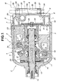
- Fig. 1 is a vertical sectional view of an embodiment of a swash plate type compressor according to the present invention;
- Fig. 2 is a perspective view of a rear housing of the swash plate type compressor of Fig. 1, as viewed from the rear side; and
- Fig. 3 is a fragmentary sectional view of an end wall of the rear housing of Fig. 2.
-
- Referring now to Figs. 1 to 3, a first embodiment of a swash plate type compressor according to the present invention is illustrated by the reference character C. The swash type compressor C of this embodiment is a variable displacement compressor and used for pressurizing refrigerant in an air conditioning system (not shown) of an automotive vehicle. The compressor C comprises a compressor housing 1 which includes a
cylinder block 2. Thecylinder block 2 is formed with a plurality ofcylinder bores 3. Afront housing 4 is disposed in front of thecylinder block 2 and fixedly connected to thecylinder block 2 to define thereinside acrank chamber 5. Arear housing 6 is disposed behind thecylinder block 2 and fixedly connected to thecylinder block 2 through avalve plate 9. Therear housing 6 is formed with a refrigerant suction chamber 7 and arefrigerant discharge chamber 8. Therefrigerant discharge chamber 8 is located at the diametrically central section of the rear housing, while the refrigerant suction chamber 7 is located at the diametrically outer peripheral section of therefrigerant discharge chamber 8. - A
drive shaft 10 is disposed to axially extend through thefront housing 4 and thecylinder block 3. Adrive plate 11 is fixedly mounted on thedrive shaft 10 and located in thecrank chamber 5. Asleeve 12 is slidably mounted on thedrive shaft 10. Ajournal 14 is swingably connected throughpins 13 to thesleeve 12. Thejournal 14 has aboss section 15 which is formed at its outer peripheral surface with anexternal thread portion 16. A generally annular disc-shaped swash plate 17 is fixedly and coaxially mounted on theboss section 15 of thejournal 14 in such a manner that aninternal thread 18 of theswash plate 17 is engaged with theexternal thread portion 16 of thejournal 14. Thejournal 14 has ahinge arm 19 which is movably connected to ahinge arm 20 of thedrive plate 11 in such a manner that apin 22 of thehinge arm 19 is slidably disposed within anelongate hole 21 of thehinge arm 20, so that swingable movement of thejournal 14 is restricted under the action of theelongate hole 21. - A
piston 23 is movably disposed inside eachcylinder bore 3. Eachpiston 23 is connected to theswash plate 17 through a pair ofshoes 24 which are located respectively on the opposite sides ofswash plate 17. Theswash plate 17 is inclinable relative to an imaginary plane (not shown) to which the axis of thedrive shaft 10 is perpendicular, thereby forming an inclination angle. The inclination angle of theswash plate 17 is changed by a pressure within thecrank chamber 5 which pressure is adjusted in accordance with a pressure within the refrigerant suction chamber 7 under the action of a pressure control valve mechanism (not shown). Such change in inclination angle of theswash plate 17 changes the stroke of eachpiston 23 thereby altering the amount of refrigerant discharged from the compressor C. - The
valve plate 9 is formed with discharge holes 30 and suction holes 32 through which refrigerant flows in and out of the cylinder bores 3. The discharge holes 30 are closable with alead valve 29. Thelead valve 29 is restricted in its movement by aretainer 33. The suction holes 32 are closable withlead valves 31. - The basic construction and operation of the swash plate type compressor C are known as disclosed in United States Patent No. 5,706,716 entitled "Variable Displacement Swash Plate Type Compressor", and United States Patent No. 5,749,712 entitled "Variable Displacement Swash Plate Type Compressor" which are hereby incorporated by reference.
- In this embodiment, the
rear housing 6 includes abase section 6a which is formed thereinside with the refrigerant suction chamber 7 and amain part 8a of therefrigerant discharge chamber 8. The refrigerant suction chamber 7 is formed at the generally diametrically peripheral section of the rearhousing base section 6a and fluidly connectable through the suction holes 32 with the cylinder bores 3. Therefrigerant discharge chamber 8 is formed at the generally diametrically central section of the rearhousing base section 6a and fluidly connectable through the suction holes 32 with the cylinder bores 3. - The
rear housing 6 is integrally formed at its end wall E with a bulged or projectedsection 25 which projects rearward or in a direction opposite to thecylinder block 2. The bulgedsection 25 are located at the generally diametrically central section of the end wall E of therear housing 6 and positioned corresponding to themain part 8a of therefrigerant discharge chamber 8. The inside of the bulgedsection 25 is depressed to form an inside depression D (shown in Fig. 3) which forms anauxiliary part 8b of therefrigerant discharge chamber 8. Theauxiliary part 8b is merged in themain part 8a to form therefrigerant discharge chamber 8. - The bulged
section 25 of therear housing 6 is formed at its rear flat surface with alinear groove 26 which is located at the generally central section and extends diametrically. Thelinear groove 26 has a size sufficient to receive an installation bolt B (or a nut) as shown in phantom in Fig. 1. It will be understood that thelinear groove 26 is separate and independent from therefrigerant discharge chamber 8 by a wall portion W of therear housing 6 as shown in Fig. 3. In other words, the wall portion W is generally channel-shaped to define thereoutside thelinear groove 26 and forms part of the end wall E of therear housing 6, so that thelinear groove 26 is completely isolated from therefrigerant discharge chamber 8. - The opposite end sections of the
linear groove 26 are closed respectively withbracket walls bolt insertion hole 28 through which the bolt is insertable as indicated in phantom in Fig. 1. Thebracket walls section 25. In this connection, the bulgedsection 25 projects rearward by a distance corresponding to a rearward projection distance (height) of thebracket walls rear housing 6 is fixed to an engine block M of the vehicle. In this embodiment, therear surface 27a of eachbracket wall 27 is flush with therear surface 25a of the bulgedsection 25 as shown in Fig. 3. - With the above-arranged compressor C, the bulged
section 25 is formed at the end wall E of therear housing 6 so as to project rearward and be located corresponding to the refrigerant discharge chambermain part 8a. Accordingly, the volume of therefrigerant discharge chamber 8 is enlarged thereby suppressing pulsation of refrigerant to be discharged from the compressor C thus improving stillness of the compressor C. This prevents such pulsation from being transmitted to the inside of a passenger compartment via piping of a refrigeration cycle of the air conditioning system, thus improving also stillness inside the passenger compartment. - Additionally, the bulged
section 25 is formed with thelinear groove 26 and integrally provided with thebracket walls linear groove 26. Accordingly, the installation bolt B is located in thelinear groove 26, in which the bolt B is fixed to therear housing 6 by thebracket walls rear housing 6 is fixed to the engine block M as shown in phantom in Fig. 1. - Further, the
bracket walls section 25. In other words, the bulgedsection 25 is formed or molded having a predetermined projection height (rearward projection distance) corresponding to that of thebracket walls refrigerant discharge chamber 8 can be enlarged. Thus, it is achieved to enlarge the volume of therefrigerant discharge chamber 8 and to provide brackets (or thebracket walls 27, 27) to the end wall E of therear housing 6, without changing the whole length of the compressor C. This realizes making the compressor C small-sized. - Furthermore, the
bracket walls section 25 so as to serve as closing walls, and therefore stiffness of thebracket walls - Particularly in this embodiment, the bulged
section 25 is formed at the diametrically central section of the end wall E of therear housing 6 and located corresponding to the refrigeration discharge chambermain part 8a located at the diametrically central section of the rearhousing base section 6a. Accordingly, the diametrical dimension of the bulgedsection 25 can be reduced as small as possible thereby to contribute to making the compressor C light in weight, while thegroove 26 is formed diametrically extending so that thebracket walls bracket walls - While the bulged
section 25 has been shown and described as being formed bulged at the section corresponding the centrally located refrigerant discharge chambermain part 8a in the rearhousing base section 6a in this embodiment, it will be understood that the bulgedsection 25 may be formed by wholly projecting rearward the end wall E of therear housing 6 including a section corresponding to the refrigerant suction chamber 7. - Although only the variable displacement type and swash plate type compressor has been shown and described, it will be appreciated that the principle of the present invention may be applicable to a swash plate type compressor of the structure wherein an inclination angle of the swash plate is constant.
Claims (5)
- A swash plate type compressor for refrigerant, comprising:a cylinder block having a plurality of cylinder bores;a plurality of pistons which are respectively fitted in said cylinder bores, each piston making a linear movement under action of a swash plate which is rotatable with a drive shaft; anda rear housing having a refrigerant suction chamber and a refrigerant discharge chamber, said rear housing having first and second end sections, the first end section being connected through a valve plate to an end section of said cylinder block, said refrigerant suction chamber and said refrigerant discharge chamber being connectable with said cylinder bores of said cylinder block through holes formed in said valve plate, said rear housing includinga base section connected through said valve plate to said cylinder block and being formed thereinside with a first part of said refrigerant discharge chamber,a bulged section integral with said base section and projecting in a direction opposite to said cylinder block, said bulged section having an inside depression which forms a second part of said refrigerant discharge chamber, said bulged section having a linear groove formed at a surface forming part of said second end section of said rear housing and depressed in a direction of said first end section of said rear housing, andbracket walls formed integral with said bulged section to close opposite end sections of said linear groove.
- A swash type compressor as claimed in Claim 1, wherein each of said bracket walls is formed with a hole which is aligned with said linear groove.
- A swash type compressor as claimed in Claim 1, wherein said first part of said refrigerant discharge chamber is formed at a generally diametrically central section of said rear housing base section, said refrigerant suction chamber being formed diametrically outside of said refrigerant discharge chamber, wherein said bulged section is formed on a generally diametrically central section of said base section so as to correspond to the first part of said refrigerant discharge chamber.
- A swash type compressor as claimed in Claim 1, wherein said bulged section has a wall integral with a wall of said base section, said wall of said bulged section including a generally channel-shaped wall portion which defines thereoutside said linear groove and thereinside said refrigerant discharge chamber, said linear groove being isolated from said refrigerant discharge chamber through said channel-shaped wall portion.
- A swash type compressor as claimed in Claim 4, wherein said bracket walls are integral with said channel-shaped wall portion and located at opposite end sections of said channel-shaped wall portion so as to block the opposite end sections of said linear groove.
Applications Claiming Priority (3)
| Application Number | Priority Date | Filing Date | Title |
|---|---|---|---|
| JP288761/97 | 1997-10-21 | ||
| JP28876197A JP3880158B2 (en) | 1997-10-21 | 1997-10-21 | Swash plate compressor |
| JP28876197 | 1997-10-21 |
Publications (3)
| Publication Number | Publication Date |
|---|---|
| EP0911519A2 true EP0911519A2 (en) | 1999-04-28 |
| EP0911519A3 EP0911519A3 (en) | 1999-07-07 |
| EP0911519B1 EP0911519B1 (en) | 2003-08-20 |
Family
ID=17734376
Family Applications (1)
| Application Number | Title | Priority Date | Filing Date |
|---|---|---|---|
| EP98119821A Expired - Lifetime EP0911519B1 (en) | 1997-10-21 | 1998-10-19 | Housing for the valve plate assembly of a swash plate compressor |
Country Status (4)
| Country | Link |
|---|---|
| US (1) | US6146110A (en) |
| EP (1) | EP0911519B1 (en) |
| JP (1) | JP3880158B2 (en) |
| DE (1) | DE69817291T2 (en) |
Cited By (2)
| Publication number | Priority date | Publication date | Assignee | Title |
|---|---|---|---|---|
| EP1085207A2 (en) * | 1999-09-14 | 2001-03-21 | Kabushiki Kaisha Toyoda Jidoshokki Seisakusho | Compressor having structure for suppressing pulsation |
| EP1394410A2 (en) * | 2002-08-29 | 2004-03-03 | Halla Climate Control Corporation | Compressor having reduced pressure pulsation |
Families Citing this family (5)
| Publication number | Priority date | Publication date | Assignee | Title |
|---|---|---|---|---|
| JP2001065452A (en) * | 1999-08-26 | 2001-03-16 | Toyota Autom Loom Works Ltd | Die cast piston and its manufacturing method |
| JP2002174170A (en) * | 2000-09-29 | 2002-06-21 | Sanden Corp | Swash plate type compressor |
| US6439857B1 (en) * | 2001-03-12 | 2002-08-27 | Haldex Brake Corporation | Axial piston compressor |
| JP5409065B2 (en) * | 2009-03-19 | 2014-02-05 | 三菱重工業株式会社 | Compressor |
| US8196506B2 (en) * | 2009-08-17 | 2012-06-12 | Delphi Technologies, Inc. | Variable stroke compressor design |
Citations (3)
| Publication number | Priority date | Publication date | Assignee | Title |
|---|---|---|---|---|
| JPH05195949A (en) | 1992-01-21 | 1993-08-06 | Toyota Autom Loom Works Ltd | Reciprocating compressor |
| US5706716A (en) | 1995-04-13 | 1998-01-13 | Calsonic Corporation | Variable displacement swash plate type compressor |
| US5749712A (en) | 1995-09-14 | 1998-05-12 | Calsonic Corporation | Variable displacement swash plate type compressor |
Family Cites Families (18)
| Publication number | Priority date | Publication date | Assignee | Title |
|---|---|---|---|---|
| US3864801A (en) * | 1971-02-24 | 1975-02-11 | Toyoda Automatic Loom Works | Swash plate compressor |
| US3930758A (en) * | 1974-03-22 | 1976-01-06 | General Motors Corporation | Means for lubricating swash plate air conditioning compressor |
| CA1140515A (en) * | 1978-12-04 | 1983-02-01 | Byron L. Brucken | Swash plate compressor |
| US4360321A (en) * | 1980-05-20 | 1982-11-23 | General Motors Corporation | Multicylinder refrigerant compressor muffler arrangement |
| JPS59135385U (en) * | 1983-03-02 | 1984-09-10 | 株式会社豊田自動織機製作所 | Swash plate compressor |
| JPS6217380A (en) * | 1985-07-16 | 1987-01-26 | Diesel Kiki Co Ltd | Swash plate type rotary compressor |
| EP0264833B1 (en) * | 1986-10-17 | 1991-03-20 | Sanden Corporation | Mounting mechanism for compressor in an automotive air conditioning system |
| JPH07111171B2 (en) * | 1989-11-02 | 1995-11-29 | 株式会社豊田自動織機製作所 | Continuously variable capacity swash plate compressor |
| JP3111684B2 (en) * | 1992-09-17 | 2000-11-27 | 株式会社豊田自動織機製作所 | Variable capacity swash plate compressor |
| JP3326909B2 (en) * | 1993-10-07 | 2002-09-24 | 株式会社豊田自動織機 | Swash plate type variable displacement compressor |
| KR970007656B1 (en) * | 1994-03-09 | 1997-05-15 | 가부시끼가이샤 도요다 지도쇽끼 세이사꾸쇼 | Clutchless variable displacement type compressor |
| US5624240A (en) * | 1994-06-27 | 1997-04-29 | Kabushiki Kaisha Toyoda Jidoshokki Seisakusho | Piston type variable displacement compressor |
| JP3417067B2 (en) * | 1994-07-29 | 2003-06-16 | 株式会社豊田自動織機 | Variable displacement compressor |
| JPH0861239A (en) * | 1994-08-16 | 1996-03-08 | Toyota Autom Loom Works Ltd | Refrigerant gas suction structure of piston type compressor |
| JP3197759B2 (en) * | 1994-08-22 | 2001-08-13 | 株式会社ゼクセルヴァレオクライメートコントロール | Full stroke positioning structure of variable displacement compressor |
| JPH08170588A (en) * | 1994-12-16 | 1996-07-02 | Toyota Autom Loom Works Ltd | Reciprocating compressor |
| JP3695724B2 (en) * | 1996-03-19 | 2005-09-14 | カルソニックカンセイ株式会社 | Manufacturing method of single-headed piston of swash plate compressor |
| JPH10213062A (en) * | 1997-01-31 | 1998-08-11 | Zexel Corp | Variable displacement swash plate compressor |
-
1997
- 1997-10-21 JP JP28876197A patent/JP3880158B2/en not_active Expired - Lifetime
-
1998
- 1998-10-19 EP EP98119821A patent/EP0911519B1/en not_active Expired - Lifetime
- 1998-10-19 DE DE69817291T patent/DE69817291T2/en not_active Expired - Lifetime
- 1998-10-20 US US09/175,418 patent/US6146110A/en not_active Expired - Fee Related
Patent Citations (3)
| Publication number | Priority date | Publication date | Assignee | Title |
|---|---|---|---|---|
| JPH05195949A (en) | 1992-01-21 | 1993-08-06 | Toyota Autom Loom Works Ltd | Reciprocating compressor |
| US5706716A (en) | 1995-04-13 | 1998-01-13 | Calsonic Corporation | Variable displacement swash plate type compressor |
| US5749712A (en) | 1995-09-14 | 1998-05-12 | Calsonic Corporation | Variable displacement swash plate type compressor |
Cited By (4)
| Publication number | Priority date | Publication date | Assignee | Title |
|---|---|---|---|---|
| EP1085207A2 (en) * | 1999-09-14 | 2001-03-21 | Kabushiki Kaisha Toyoda Jidoshokki Seisakusho | Compressor having structure for suppressing pulsation |
| EP1085207A3 (en) * | 1999-09-14 | 2002-01-23 | Kabushiki Kaisha Toyota Jidoshokki | Compressor having structure for suppressing pulsation |
| EP1394410A2 (en) * | 2002-08-29 | 2004-03-03 | Halla Climate Control Corporation | Compressor having reduced pressure pulsation |
| EP1394410A3 (en) * | 2002-08-29 | 2004-06-23 | Halla Climate Control Corporation | Compressor having reduced pressure pulsation |
Also Published As
| Publication number | Publication date |
|---|---|
| DE69817291T2 (en) | 2004-06-17 |
| US6146110A (en) | 2000-11-14 |
| JP3880158B2 (en) | 2007-02-14 |
| DE69817291D1 (en) | 2003-09-25 |
| JPH11125178A (en) | 1999-05-11 |
| EP0911519A3 (en) | 1999-07-07 |
| EP0911519B1 (en) | 2003-08-20 |
Similar Documents
| Publication | Publication Date | Title |
|---|---|---|
| US7918656B2 (en) | Suction throttle valve of a compressor | |
| US7771175B2 (en) | Variable displacement compressor | |
| EP0908623A2 (en) | Reciprocating pistons of piston-type compressor | |
| EP0798461A2 (en) | Refrigerant circuit with fluid flow control mechanism | |
| US5800133A (en) | Compressor with discharge chamber relief valve | |
| JP4606433B2 (en) | Variable capacity swash plate compressor | |
| EP0911519B1 (en) | Housing for the valve plate assembly of a swash plate compressor | |
| EP1008751B1 (en) | Compressor | |
| US6045342A (en) | Refrigerant compressor | |
| US6120259A (en) | Swash plate type compressor | |
| US20070175239A1 (en) | Refrigerant compressor | |
| US6488481B1 (en) | Compressor with suction muffler structure | |
| EP1394410B1 (en) | Compressor having reduced pressure pulsation | |
| US20030095876A1 (en) | Swash plate type compressor | |
| US6382938B1 (en) | Compressor having structure for suppressing pulsation | |
| EP1548281A2 (en) | Piston type compressor | |
| US6212995B1 (en) | Variable-displacement inclined plate compressor | |
| US6227811B1 (en) | Variable capacity swash plate type compressor | |
| US6579071B1 (en) | Structure for suppressing pulsation in compressor | |
| US20020127118A1 (en) | Compressor | |
| US20090238698A1 (en) | Reciprocal Compressor | |
| US6179576B1 (en) | Reciprocating compressor | |
| US20040202551A1 (en) | Variable displacement compressor | |
| US6378417B1 (en) | Swash plate compressor in which an opening edge of each cylinder bore has a plurality of chamferred portions | |
| EP1233180A2 (en) | Compressor housing |
Legal Events
| Date | Code | Title | Description |
|---|---|---|---|
| PUAI | Public reference made under article 153(3) epc to a published international application that has entered the european phase |
Free format text: ORIGINAL CODE: 0009012 |
|
| 17P | Request for examination filed |
Effective date: 19981019 |
|
| AK | Designated contracting states |
Kind code of ref document: A2 Designated state(s): DE FR GB |
|
| AX | Request for extension of the european patent |
Free format text: AL;LT;LV;MK;RO;SI |
|
| PUAL | Search report despatched |
Free format text: ORIGINAL CODE: 0009013 |
|
| AK | Designated contracting states |
Kind code of ref document: A3 Designated state(s): AT BE CH CY DE DK ES FI FR GB GR IE IT LI LU MC NL PT SE |
|
| AX | Request for extension of the european patent |
Free format text: AL;LT;LV;MK;RO;SI |
|
| AKX | Designation fees paid |
Free format text: DE FR GB |
|
| RAP1 | Party data changed (applicant data changed or rights of an application transferred) |
Owner name: CALSONIC KANSEI CORPORATION |
|
| GRAH | Despatch of communication of intention to grant a patent |
Free format text: ORIGINAL CODE: EPIDOS IGRA |
|
| GRAS | Grant fee paid |
Free format text: ORIGINAL CODE: EPIDOSNIGR3 |
|
| GRAA | (expected) grant |
Free format text: ORIGINAL CODE: 0009210 |
|
| AK | Designated contracting states |
Designated state(s): DE FR GB |
|
| REG | Reference to a national code |
Ref country code: GB Ref legal event code: FG4D |
|
| REF | Corresponds to: |
Ref document number: 69817291 Country of ref document: DE Date of ref document: 20030925 Kind code of ref document: P |
|
| ET | Fr: translation filed | ||
| PLBE | No opposition filed within time limit |
Free format text: ORIGINAL CODE: 0009261 |
|
| STAA | Information on the status of an ep patent application or granted ep patent |
Free format text: STATUS: NO OPPOSITION FILED WITHIN TIME LIMIT |
|
| 26N | No opposition filed |
Effective date: 20040524 |
|
| PGFP | Annual fee paid to national office [announced via postgrant information from national office to epo] |
Ref country code: FR Payment date: 20101020 Year of fee payment: 13 |
|
| PGFP | Annual fee paid to national office [announced via postgrant information from national office to epo] |
Ref country code: DE Payment date: 20101013 Year of fee payment: 13 |
|
| PGFP | Annual fee paid to national office [announced via postgrant information from national office to epo] |
Ref country code: GB Payment date: 20101013 Year of fee payment: 13 |
|
| GBPC | Gb: european patent ceased through non-payment of renewal fee |
Effective date: 20111019 |
|
| REG | Reference to a national code |
Ref country code: FR Ref legal event code: ST Effective date: 20120629 |
|
| PG25 | Lapsed in a contracting state [announced via postgrant information from national office to epo] |
Ref country code: DE Free format text: LAPSE BECAUSE OF NON-PAYMENT OF DUE FEES Effective date: 20120501 |
|
| REG | Reference to a national code |
Ref country code: DE Ref legal event code: R119 Ref document number: 69817291 Country of ref document: DE Effective date: 20120501 |
|
| PG25 | Lapsed in a contracting state [announced via postgrant information from national office to epo] |
Ref country code: FR Free format text: LAPSE BECAUSE OF NON-PAYMENT OF DUE FEES Effective date: 20111102 Ref country code: GB Free format text: LAPSE BECAUSE OF NON-PAYMENT OF DUE FEES Effective date: 20111019 |