EP0910859B1 - Appareil de coupure tel qu'un commutateur-inverseur pour une installation electrique - Google Patents
Appareil de coupure tel qu'un commutateur-inverseur pour une installation electrique Download PDFInfo
- Publication number
- EP0910859B1 EP0910859B1 EP97947093A EP97947093A EP0910859B1 EP 0910859 B1 EP0910859 B1 EP 0910859B1 EP 97947093 A EP97947093 A EP 97947093A EP 97947093 A EP97947093 A EP 97947093A EP 0910859 B1 EP0910859 B1 EP 0910859B1
- Authority
- EP
- European Patent Office
- Prior art keywords
- control shaft
- switchgear
- switchgear according
- control
- block
- Prior art date
- Legal status (The legal status is an assumption and is not a legal conclusion. Google has not performed a legal analysis and makes no representation as to the accuracy of the status listed.)
- Expired - Lifetime
Links
Images


Classifications
-
- H—ELECTRICITY
- H01—ELECTRIC ELEMENTS
- H01H—ELECTRIC SWITCHES; RELAYS; SELECTORS; EMERGENCY PROTECTIVE DEVICES
- H01H19/00—Switches operated by an operating part which is rotatable about a longitudinal axis thereof and which is acted upon directly by a solid body external to the switch, e.g. by a hand
- H01H19/54—Switches operated by an operating part which is rotatable about a longitudinal axis thereof and which is acted upon directly by a solid body external to the switch, e.g. by a hand the operating part having at least five or an unspecified number of operative positions
- H01H19/60—Angularly-movable actuating part carrying no contacts
- H01H19/635—Contacts actuated by rectilinearly-movable member linked to operating part, e.g. by pin and slot
-
- H—ELECTRICITY
- H01—ELECTRIC ELEMENTS
- H01H—ELECTRIC SWITCHES; RELAYS; SELECTORS; EMERGENCY PROTECTIVE DEVICES
- H01H11/00—Apparatus or processes specially adapted for the manufacture of electric switches
- H01H11/0006—Apparatus or processes specially adapted for the manufacture of electric switches for converting electric switches
-
- H—ELECTRICITY
- H01—ELECTRIC ELEMENTS
- H01H—ELECTRIC SWITCHES; RELAYS; SELECTORS; EMERGENCY PROTECTIVE DEVICES
- H01H9/00—Details of switching devices, not covered by groups H01H1/00 - H01H7/00
- H01H9/0066—Auxiliary contact devices
Definitions
- the present invention relates to a breaking device such as a change-over switch for an electrical installation, this device comprising at least two superimposed cut-off blocks, each cut-off block comprising at least two pairs of terminals intended to be connected to at least two phases of said phase installation, at least two pairs of fixed contacts coupled to said terminals and to at least two movable contacts with two stable positions, one closed position in which each movable contact connects the fixed contacts of the same pair to establish the passage of electric current and an open position in which each contact mobile separates said fixed contacts to interrupt the passage of said current electric, the movable contacts being mounted on a common movable bar arranged to move in translation, said apparatus also comprising at least two actuating blocks, each being arranged to move said movable bar of the block corresponding cutoff, and a control block provided with a control shaft can be coupled to a handle and arranged to simultaneously control said actuation blocks.
- a breaking device such as a change-over switch for an electrical installation
- this device comprising at least two superimposed cut
- Such switching devices are generally used for electrical distribution at low voltage single-phase, three-phase or four-phase, the intensity ranging from a few tens to several hundred amps. they ensure the switching, the inversion of source or load swap of two low voltage power circuits as well as their safety sectioning.
- a switching device equivalent to a change-over switch two switches are superimposed in known manner standards placed in the same direction, each consisting of a cut-off block, its actuation block and its control block, which requires having the all parts in duplicate. Then we couple the control handle of the upper switch to the two actuation blocks by extending the shaft of control of said control block by a specific shaft extension, the points connecting rods provided in the actuation blocks being modified on the shaft control.
- the handle can have three stable positions, a middle position "0" and two positions "I", "II” on either side of the middle position, for example at - 65 ° and at + 65 °.
- Reversing switches of this type allow only only two switching combinations: in the first combination, one of the switches is closed when the other is open and, in the middle position, both switches are open. In the second combination, one of the switches is closed when the other is open and, in the middle position, the two switches are closed simultaneously.
- the object of the present invention is to overcome the drawbacks mentioned above by making a breaking device, such as a change-over switch, in which the actuation block and the control block were the subject value analysis and have been optimized to reduce the number of coins and necessary references, facilitate assembly, allow realization simply and at lower cost of a "bypass" type device or a 6 or 8 pole device. Moreover, the optimization of said blocks makes it possible to offer a number of combinations of switching greater than two. As a result, a cutting device is obtained having a best value for money with new features.
- the reduction and simplification of the number of parts and references favor the reduction of the price of returns from the set and simplifies management. For example, the number of pieces and of references can be divided by three compared to standard switching devices.
- a switching device as defined in the preamble and characterized in that the actuating blocks overlap back to back and are arranged between the cut-off blocks reversed with respect to each other.
- the actuation blocks may each include a housing provided with at least one bottom, the two housings being arranged to fit into each other at their bottom or may include a single and common housing provided with at least one wall central unit constituting the bottom of each actuation block.
- each actuation block comprises at least one connecting rod coupled at one of its ends to the control shaft and a drive rod pivotally mounted about a fixed central axis on said housing and coupled on the one hand to the free end of the connecting rod and on the other hand to the bar mobile of the corresponding cut-off block.
- each actuation block includes an accumulation device energy in the form of a spring provided with two free ends, one being integral with the housing and the other with the drive rod, this spring making it possible to quickly switch the corresponding switch block.
- the drive rod is preferably coupled to the bar by at least one post housed in a corresponding recess provided in said bar and delimited by two stops, this tenon being integral with the corresponding free end of the spring.
- the drive rod is coupled to the rod by at least a first pin, this pin being guided in a first groove provided in said housing and extending over an arc centered on the axis of pivoting of said drive rod.
- the groove can extend over an angular sector slightly less than 180 °, the housing having a second identical groove, diametrically opposite, arranged to guide a second pin provided on the drive rod opposite the first journal.
- the connecting rod, the drive rod and the spring are removable parts, their configuration being modifiable so as to create several switching combinations between the two switching blocks.
- control shaft is guided in rotation in the body of said control unit and is coupled to an accessible handle outside the device, this control shaft being coupled to the connecting rods of the two actuation blocks at two separate pivot points.
- the control shaft advantageously comprises two opposite, parallel disks between them and perpendicular to the axis of rotation Y of the control shaft, each disc comprising at least one pivot arranged to be housed in a housing suitable provided in the corresponding connecting rod.
- the housing provided in the end of the connecting rods mounted on the pivots of the control shaft has an oblong shape arranged to allow a set of operation between the shaft and the corresponding connecting rod.
- At least one disc has at least two locations suitable for receiving said pivot so as to modify the point of pivoting of the connecting rods on said control shaft.
- the connecting rods have a first defined length
- the pivots receiving the connecting rods on the control axis are arranged symmetrically with respect to the longitudinal axis X of the device passing through the axis of Y rotation of the drive shaft and the drive shaft has three positions stable corresponding to three positions of the handle: a middle position "0" and two positions "I” and "II” at right angles on either side of the middle position.
- the connecting rods have a second length defined less than the first length
- the pivots receiving the connecting rods on the shaft control are diametrically opposed with respect to the axis of rotation Y of the shaft of control and the control shaft has two stable positions corresponding to two positions "I" and "II" at right angles to the handle.
- the control shaft advantageously comprises at least one cam arranged to actuate at least one auxiliary contact mounted in said device, the body of the block control being provided with at least one interior housing for receiving said contact auxiliary.
- control shaft has at its end opposite to the control handle a square section arranged to control a third cut-off block provided on said device.
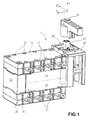
- the switching device 1 corresponds to a change-over switch and has two cut-off blocks 10, 20 superimposed, one upper block 10 and a lower block 20, returned relative to each other. he also comprises two actuating blocks 30, 40, one for each block of break, arranged back to back and grouped in a common box 50 mounted between the two cut-off blocks 10, 20. Finally, it includes a control block 60 arranged generally to the right of the actuating blocks 30, 40 and provided with a shaft control 64 can receive a control handle 61. It is a handle with three stable positions, a middle position called "0" and two positions called “I” and “II" at right angles on either side of the middle position, an angle of total operation of 180 °.
- Each cut-off block 10, 20 comprises, so known, at least two and, in this case, four pairs of connection terminals 11, 21 intended to be connected to the electrical conductors of an installation, in this case, four-pole, three phases and one neutral.
- each block break 10, 20 has as many pairs of fixed contacts as pairs of terminals connection and as many mobile contacts as pairs of fixed contacts.
- the movable contacts are mounted on a movable bar arranged to slide in translation between two stable positions: a closed position when the contacts mobile connect the corresponding pairs of fixed contacts and that the electrical connection is ensured, and an open position when the movable contacts separate the pairs of corresponding fixed contacts and that the electrical connection is interrupted.
- each cut-off block 10, 20 is actuated by its actuation block 30, 40, which is controlled by the control block 60.
- This control block 60 is closed in its upper part by a plate called “plastron” 62 and can be opened in its lower part. It has a height equivalent to that of the cut-off block upper 10 and actuating blocks 30, 40. It does not need to be extend beyond.
- the cut-off blocks 10, 20 and actuation blocks 30, 40 are fitted into each other by means of complementary profiles and are held by fixing screws 12 visible in Figure 1 on the upper side of the upper disconnection block 10.
- the switching device 1 is shown partially and in exploded view.
- the control handle and the cut-off block lower have been removed.
- the front plate 62 and the upper cut-off block 10 have been raised to show the inside of the upper actuator block 30, the inside of the control block 60 and the underside of the upper cut-off block 10 with its bar mobile 13.
- the actuating blocks 30, 40 are grouped in the common housing 50 provided with side walls 51 and a central wall 52 separating the housing 50 into two equal parts in the direction of its height, this wall median 52 constituting the bottom of each actuating block 30, 40.
- the common housing 50 is made in one piece with the body 63 of the control block 60 to simplify their manufacture and assembly.
- This common box 50 in two separate, identical and nestable boxes, one for each actuating block 30, 40.
- This embodiment is advantageous because it makes it possible to manufacture switches simple with the same housing.
- the control unit 60 comprises a shaft of control 64 guided in rotation in the body 63, this shaft being connected to the handle control 61 by square coupling 65.
- the actuating blocks 30, 40 are identical but reversed with respect to each other since they are placed back to back of on either side of the middle wall 52 of the common housing 50. The same parts will bear the same reference.
- Each actuating block 30, 40 comprises a connecting rod 31, a first end of which is coupled to the control shaft 64 and a link drive 32 pivotally mounted about a central axis 33 fixed relative to the case 50.
- Said link 32 is coupled on the one hand to the second end of the link 31 and on the other hand to the movable bar 13 of the corresponding cut-off block 10, 20.
- Each actuating block 30, 40 also includes an accumulation device energy in the form of a spring 34, more precisely consisting of a spring torsion, provided with two free ends 35, 36, one 35 secured to the housing 50 and the other 36 secured to the link 32.
- This torsion spring 34 allowing the action abrupt mechanism, accelerates the switching of the movable bar 13 and by therefore the switching of the corresponding movable contacts, i.e. the passage from the open position to the closed position and vice versa.
- the link between the connecting rod 31 and the connecting rod 32 takes place around a first pin 37 guided in a first groove 38 in an arc, provided in the housing 50 and extending over a angular sector slightly less than 180 °, the center of which coincides with the axis pivot 33 of the link 32.
- a second pin 39 is provided on the link 32, diametrically opposite to the first 37, and arranged to slide in a second identical groove 41, with the same center and symmetrical.
- the link between the link 32 and the movable bar 13 of the corresponding cutting block 10, 20 is effected by a tenon 42 secured to the link 32 and housed in a recess 14 formed in the bar 13.
- This recess is delimited by two stops 15, 16 allowing movement in translation of the tenon 42 relative to the bar 13.
- This tenon 42 is stressed by the spring 34, its corresponding free end 36 being housed in an orifice through 43 provided in said stud 42.
- All the parts making up a block actuator 30, 40 namely the rod 31, the drive rod 32 and the spring 34, are assembled by interlocking and are therefore easily removable. This allows their respective positions to be changed in the same actuation block 30, 40 and from one block to another.
- the different configurations obtained allow to realize different switching combinations between the two cut-off blocks 10, 20.
- the link 32 can be coupled to the link 31 at its end carrying the pin 42.
- the link 32 can be positioned in the other direction, the position of the spring being also modified.
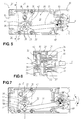
- FIG 3 partially illustrates the apparatus 1 of Figure 2 and in particular the block of lower cutout 20 with its movable bar 13, the control shaft 64 and the two actuating blocks 30, 40 without the springs or the common housing 50.
- This shaft control 64 comprises two discs 66, 67 parallel to each other and perpendicular to the axis of rotation Y of said shaft, each disc being provided with a pivot 68, 69 for each connecting rod 31.
- the two pivots 68, 69 are not directly superimposed, they are offset from each other. Their respective position on their disc 66, 67 can be modified as we will see later.
- each connecting rod 31 has an oblong housing 44 capable of receiving its pivot 68, 69, which leaves the rod 31 a certain play in its displacement relative to the shaft of command 64, the value of which is explained below.
- This figure illustrates the connecting rods 31 and the drive rods 32 of the two actuating blocks 30, 40 in the same configuration but returned one relative to the other.
- the pin 42 of the link 32 of the lower actuating block 40 is housed in the recess 14 of the movable bar 13 of the lower cutout block 20.
- the cams 71 are arranged to control auxiliary contacts 80 in operation the position of the control shaft 64.
- One or more auxiliary contacts 80 to opening or closing are generally associated with each cut-off block to allow the transmission via an electrical link of information relating to the position of these cut-off blocks 10, 20 towards one or more control circuits or monitoring (auxiliary relays, PLCs, alarms, etc.).
- the contacts auxiliaries provide precut information to the equipment connected in downstream to trigger them before the triggering of the block (s) concerned.
- These auxiliary contacts 80 are of the standard type and include a piston 81 directly controlled by the cams 71 provided on the shaft control 64. If necessary, additional auxiliary contacts 82 can be added opposite the barrel 72.
- these auxiliary contacts 82 are controlled by a paddle device 83 actuated by said barrel 72. All these auxiliary contacts 80, 82 are easily housed and fixed by screws in the control unit 60 to the by means of the longitudinal grooves 75 and of supports 76 provided in the body 63 of this block, visible in figure 2.
- Figures 5 to 7 illustrate in more detail the actuating blocks 30, 40 and the block control 60.
- Figure 5 is a top view of the upper actuator block 30 in which we find the control shaft 64, the connecting rod 31, its pivot link 68 shown in dotted lines with the control shaft 64, the drive rod 32, its fixed pivot axis 33, its two pins 37, 39 guided in the grooves 38, 41, the actuating pin 42 of the movable bar 13 and the spring 34.
- Figure 6 is a cross section of Figure 5 showing the blocks upper 30 and lower 40 actuator, the common housing 50 and the shaft command 64. It is clear from this figure that the parts making up each actuator block 30, 40 are arranged inversely to correspond to their cut-off block 10, 20 also reversed.
- Figure 7 illustrates the block actuator 30 of Figure 5, the control shaft 64 having rotated about 45 ° counterclockwise following arrow F.
- FIGs 8 to 12 illustrate the different possible configurations of the blocks actuation 30, 40 and therefore the different switching combinations obtained for each configuration with the device 1 according to the invention.
- the figures marked with index A represent the upper actuating block 30 seen from above and the figures bearing the index B represent the lower actuation block 40 with a view to below.
- the switching positions of the blocks 10, 20 are symbolized by “1” for the closed position and by "0" for the open position.
- the positions of the handle 61 or of the control shaft 64 are symbolized by "0” for the middle position, by "I” for the 90 ° position counterclockwise (arrow F) with respect to "0” and with “II” for the 90 ° position clockwise (arrow G) relative to "0".
- the respective position of the connecting rods 31, connecting rods 32 and 34 springs may vary.
- the position of the pivots 68, 69 can be modified. he it is specified that these modifications are made in the factory during the assembly of the devices and according to specific customer needs.
- Figures 8-10 all parts are identical from one configuration to another and the pivots 68, 69 are arranged symmetrically with respect to the longitudinal axis X.
- the configuration actuation blocks 30, 40 shown corresponds to the middle position "0" of the handle 61.
- FIGS. 8A and 8B the connecting rods 31, connecting rods 32 and spring 34 are arranged as in the preceding figures.
- the connection between the connecting rod 31 and the connecting rod 32 of each actuating block 30, 40 takes place on the first pin 37 housed in the first groove 38 and the spring 34 is substantially in the central axis Z.
- the combination is obtained following switching: upper cut-off block 10 handle (angle) lower cut-off block 20 1 I (-90 °) 0 0 0 (0) 0 0 II (+ 90 °) 1
- This combination provides a three-position change-over switch. stable with the two cut-off blocks 10, 20 in the intermediate position opened.
- This combination provides an overlapping changeover switch. contact, at three stable positions with an intermediate position where the two blocks of cut-off 10, 20 are in the closed position.
- This combination provides a three-position overlay switch stable with, in position "II", the superposition of the two cut-off blocks 10, 20 in closed position.
- This combination provides a simple switch with two stable positions with, in position "I”, the two cut-off blocks 10, 20 in the open position and, in position "II", the two cut-off blocks 10, 20 in the closed position.
- This combination provides a two-position change-over switch stable.
- the design of the actuation blocks 30, 40 and of the control block 60 authorizes a great flexibility of use.
- the common box 50 comprising the blocks actuation 30, 40 can be used without modification despite the difference in length of the cut-off blocks 10, 20.
- a simple "spacer” box 55 can be interposed between the two cut-off blocks 10, 20 as an extension of the common housing 50. This "spacer” box has no actuation mechanism given that the movable contact corresponding to the neutral of each cut-off block 10, 20 is mounted on the movable bar, which is actuated by said actuating blocks 30, 40 as described above.
Landscapes
- Driving Mechanisms And Operating Circuits Of Arc-Extinguishing High-Tension Switches (AREA)
- Scissors And Nippers (AREA)
Description
- la figure 1 représente en perspective un appareil de coupure tétrapolaire selon l'invention,
- la figure 2 est une vue partielle et éclatée d'un appareil de coupure tripolaire, montrant le bloc d'actionnement et le bloc de coupure supérieur soulevé,
- la figure 3 est une vue de l'axe de commande, des deux mécanismes d'actionnement et du bloc de coupure inférieur,
- la figure 4 est une vue en élévation de l'axe de commande et de contacts auxiliaires,
- la figure 5 est une vue de dessus du bloc d'actionnement,
- la figure 6 est une vue de côté en coupe suivant l'axe VI-VI de la figure 5,
- la figure 7 est une vue similaire à la figure 5 en cours de commutation,
- les figures 8a, 8b à 12a, 12b sont respectivement une vue de dessus du bloc d'actionnement supérieur et une vue de dessous du bloc d'actionnement inférieur illustrant cinq configurations de montage et de commutation possibles.
- une section carrée creuse 65 pour recevoir la poignée disposée à l'extérieur du plastron 62, laquelle est maintenue par une goupille dans un trou correspondant 65',
- une section circulaire 70 pour guider en rotation l'arbre 64 dans le plastron 62,
- des ailettes ou cames 71 décalées angulairement l'une par rapport à l'autre,
- les deux disques 66, 67 portant les pivots 68, 69 de liaison des bielles 31 et reliés par un fût 72 partiellement circulaire,
- une section circulaire 73 pour guider en rotation l'arbre 64 dans le corps 63 du bloc de commande 60, et
- une section carrée pleine 74 pour commander un éventuel troisième bloc d'actionnement.
- translation de la bielle 31,
- rotation de la biellette d'entraínement 32 autour de son axe 33,
- contrainte sur le ressort 34 et accumulation d'énergie puis, passé l'axe central Z passant par le centre des rainures 38, 41 et l'axe de pivotement 33 de la biellette 32, restitution de l'énergie accumulée générant un actionnement brusque de la biellette 32,
- translation du barreau mobile 13 du bloc de coupure 10, 20 correspondant grâce au tenon 42 de la biellette d'entraínement 32 logé dans l'évidement 14 dudit barreau.
| bloc de coupure sup. 10 | poignée (angle) | bloc de coupure inf. 20 |
| 1 | I (-90°) | 0 |
| 0 | 0(0) | 0 |
| 0 | II (+ 90°) | 1 |
| bloc de coupure sup. 10 | poignée (angle) | bloc de coupure inf. 20 |
| 1 | I (- 90°) | 0 |
| 1 | 0 (0) | 1 |
| 0 | II (+ 90°) | 1 |
| bloc de coupure sup. 10 | poignée (angle) | bloc de coupure inf. 20 |
| 0 | I(-90°) | 0 |
| 1 | 0(0) | 0 |
| 1 | II (+90°) | 1 |
| bloc de coupure sup. 10 | poignée (angle) | bloc de coupure inf. 20 |
| 0 | I(0) | 0 |
| 1 | II (+ 90°) | 1 |
| bloc de coupure sup. 10 | poignée (angle) | bloc de coupure inf. 20 |
| 1 | I(0) | 0 |
| 0 | II (+90°) | 1 |
Claims (18)
- Appareil de coupure (1) tel qu'un commutateur inverseur pour une installation électrique, cet appareil comportant au moins deux blocs de coupure (10, 20) superposés, chaque bloc de coupure comportant au moins deux paires de bornes (11) destinées à être raccordées à au moins deux phases de ladite installation, au moins deux paires de contacts fixes couplées auxdites bornes de raccordement et au moins deux contacts mobiles à deux positions stables, une position fermée dans laquelle chaque contact mobile relie les contacts fixes d'une même paire pour établir le passage du courant électrique et une position ouverte dans laquelle chaque contact mobile sépare lesdits contacts fixes pour interrompre le passage dudit courant électrique, les contacts mobiles étant montés sur un barreau mobile commun (13) agencé pour se déplacer en translation, ledit appareil comportant également au moins deux blocs d'actionnement (30, 40), chacun étant agencé pour déplacer ledit barreau mobile (13) du bloc de coupure (10, 20) correspondant et un bloc de commande (60) pourvu d'un arbre de commande (64) pouvant être couplé à une poignée (61) et agencé pour commander simultanément lesdits blocs d'actionnement (30, 40), caractérisé en ce que les blocs d'actionnement (30, 40) se superposent dos à dos et sont disposés entre les blocs de coupure (10, 20) inversés l'un par rapport à l'autre.
- Appareil selon la revendication 1, caractérisé en ce que les blocs d'actionnement (30, 40) comportent chacun un boítier pourvu d'au moins un fond, les deux boítiers étant agencés pour s'emboíter l'un dans l'autre au niveau de leur fond.
- Appareil selon la revendication 1, caractérisé en ce que les blocs d'actionnement (30, 40) comportent un boítier (50) unique et commun pourvu d'au moins une paroi centrale (52) constituant le fond de chaque bloc d'actionnement.
- Appareil selon la revendication 2 ou 3, caractérisé en ce que chaque bloc d'actionnement (30, 40) comporte au moins une bielle (31) couplée à une de ses extrémités à l'arbre de commande (64) et une biellette d'entraínement (32) montée pivotante autour d'un axe central fixe (33) sur ledit boítier (50) et couplée d'une part à l'extrémité libre de la bielle (31) et d'autre part au barreau mobile (13) du bloc de coupure correspondant (10, 20).
- Appareil selon la revendication 4, caractérisé en ce que chaque bloc d'actionnement (30, 40) comporte un dispositif d'accumulation d'énergie sous la forme d'un ressort (34) pourvu de deux extrémités libres, l'une (35) étant solidaire du boítier (50) et l'autre (36) de la biellette d'entraínement (32), ce ressort (34) permettant de commuter rapidement le bloc de coupure correspondant (10, 20).
- Appareil selon la revendication 5, caractérisé en ce que la biellette d'entraínement (32) est couplée au barreau mobile (13) par au moins un tenon (42) logé dans un évidement (14) correspondant prévu dans ledit barreau (13) et délimité par deux butées (15, 16), ce tenon étant solidaire de l'extrémité libre correspondante (36) du ressort (34).
- Appareil selon la revendication 4, caractérisé en ce que la biellette d'entraínement (32) est couplée à la bielle (31) par au moins un premier tourillon (37, 39), ce tourillon étant guidé dans une première rainure (38, 41) prévue dans ledit boítier (50) et s'étendant sur un arc de cercle centré sur l'axe de pivotement (33) de ladite biellette d'entraínement (32).
- Appareil selon la revendication 7, caractérisé en ce que la rainure (38, 41) s'étend sur un secteur angulaire légèrement inférieur à 180°, le boítier (50) comportant une seconde rainure (38, 41) identique, diamétralement opposée et agencée pour guider un second tourillon (37, 39) prévu sur la biellette d'entraínement (32) à l'opposé sur premier tourillon (37, 39)
- Appareil selon la revendication 8, caractérisé en ce que la bielle (31), la biellette d'entraínement (32) et le ressort (34) sont des pièces amovibles, leur configuration étant modifiable de manière à créer plusieurs combinaisons de commutation entre les deux blocs de coupure (10, 20).
- Appareil selon la revendication 4, caractérisé en ce que l'arbre de commande (64) est guidé en rotation dans le corps (63) dudit bloc de commande (60) et est couplé à une poignée (61) accessible à l'extérieur de l'appareil (1), cet arbre de commande étant couplé aux bielles (31) des deux blocs d'actionnement (30, 40) en deux points de pivotement distincts.
- Appareil selon la revendication 10, caractérisé en ce que l'arbre de commande (64) comporte deux disques (66, 67) en regard, parallèles entre eux et perpendiculaires à l'axe de rotation Y de l'arbre de commande (64), chaque disque comportant au moins un pivot (68, 69) agencé pour se loger dans un logement (44) approprié prévu dans la bielle correspondante (31).
- Appareil selon la revendication 11, caractérisé en ce que le logement (44) prévu dans l'extrémité des bielles (31) montée sur le pivot (68, 69) de l'arbre de commande (64) présente une forme oblongue agencée pour autoriser un jeu de fonctionnement entre l'arbre (64) et ladite bielle (31).
- Appareil selon la revendication 12, caractérisé en ce qu'au moins un disque (66, 67) comporte au moins deux emplacements aptes à recevoir ledit pivot (68, 69) de manière à modifier le point de pivotement des bielles (31) sur ledit arbre de commande (64).
- Appareil selon les revendications 9 et 13, caractérisé en ce que les bielles (31) ont une première longueur définie, en ce que les pivots (68, 69) recevant les bielles sur l'arbre de commande (64) sont disposés symétriquement par rapport à l'axe longitudinal X de l'appareil (1) passant par l'axe de rotation Y de l'arbre de commande (64), et en ce que l'arbre de commande (64) comporte trois positions stables correspondant à trois positions de la poignée (61) : une position médiane "0" et deux positions "I" et "II" à angle droit de part et d'autre de la position médiane.
- Appareil selon les revendications 9 et 13, caractérisé en ce que les bielles (31) ont une seconde longueur définie inférieure à la première longueur, en ce que les pivots (68, 69) recevant les bielles (31) sur l'arbre de commande (64) sont diamétralement opposés par rapport à l'axe de rotation Y de l'arbre de commande (64), et en ce que l'arbre de commande (64) comporte deux positions stables correspondant à deux positions "I" et "II" à angle droit de la poignée (61).
- Appareil selon la revendication 10, caractérisé en ce que l'arbre de commande (64) comporte au moins une came (71) agencée pour actionner au moins un contact auxiliaire (80) monté dans ledit appareil (1).
- Appareil selon la revendication 16, caractérisé en ce que le corps (63) du bloc de commande (60) est pourvu d'au moins un logement intérieur (75, 76) pour recevoir ledit contact auxiliaire (80).
- Appareil selon la revendication 10, caractérisé en ce que l'arbre de commande (64) comporte à son extrémité opposée à la poignée de commande (61) une section carrée (74) agencée pour commander un troisième bloc de coupure prévu sur ledit appareil (1).
Applications Claiming Priority (3)
| Application Number | Priority Date | Filing Date | Title |
|---|---|---|---|
| FR9614559A FR2756412B1 (fr) | 1996-11-25 | 1996-11-25 | Appareil de coupure tel qu'un commutateur-inverseur pour une installation electrique |
| FR9614559 | 1996-11-25 | ||
| PCT/FR1997/002083 WO1998024102A1 (fr) | 1996-11-25 | 1997-11-19 | Appareil de coupure tel qu'un commutateur-inverseur pour une installation electrique |
Publications (2)
| Publication Number | Publication Date |
|---|---|
| EP0910859A1 EP0910859A1 (fr) | 1999-04-28 |
| EP0910859B1 true EP0910859B1 (fr) | 2002-02-20 |
Family
ID=9498099
Family Applications (1)
| Application Number | Title | Priority Date | Filing Date |
|---|---|---|---|
| EP97947093A Expired - Lifetime EP0910859B1 (fr) | 1996-11-25 | 1997-11-19 | Appareil de coupure tel qu'un commutateur-inverseur pour une installation electrique |
Country Status (7)
| Country | Link |
|---|---|
| EP (1) | EP0910859B1 (fr) |
| CN (1) | CN1122289C (fr) |
| DE (1) | DE69710581T2 (fr) |
| ES (1) | ES2173496T3 (fr) |
| FR (1) | FR2756412B1 (fr) |
| HK (1) | HK1017766A1 (fr) |
| WO (1) | WO1998024102A1 (fr) |
Families Citing this family (11)
| Publication number | Priority date | Publication date | Assignee | Title |
|---|---|---|---|---|
| US7015403B2 (en) * | 2004-07-01 | 2006-03-21 | Rockwell Automation Technologies, Inc. | Disconnecting handle with auxiliary contacts for use with CDM |
| US7214895B2 (en) | 2004-07-01 | 2007-05-08 | Rockwell Automation Technologies, Inc. | Illuminated disconnecting handle for use with CDM |
| FR2954619B1 (fr) | 2009-12-17 | 2014-07-11 | Schneider Electric Ind Sas | Dispositif d'inversion de phases a bagues de contact |
| FR2979744B1 (fr) | 2011-09-01 | 2015-05-01 | Socomec Sa | Appareil de coupure electrique a haut pouvoir de fermeture |
| FR2979743B1 (fr) | 2011-09-01 | 2013-08-30 | Socomec Sa | Chariot porte contact mobile et appareil de coupure electrique equipe d'un tel chariot |
| FR2979746B1 (fr) | 2011-09-01 | 2016-07-01 | Socomec Sa | Appareil de coupure electrique a haute tenue electrodynamique |
| CN105761962B (zh) * | 2016-04-06 | 2018-05-11 | 中国船舶重工集团公司第七一二研究所 | 一种电动转换开关 |
| US10263400B2 (en) * | 2016-09-08 | 2019-04-16 | Hubbell Incorporated | Actuator assembly for electrical switches housed in an enclosure |
| CN109559928B (zh) * | 2017-09-27 | 2019-11-26 | 菏泽峥艳电力科技有限公司 | 一种大容量智能换相开关 |
| EP3537465B1 (fr) | 2018-03-09 | 2020-10-21 | Gorlan Team, S.L.U. | Module de commutateur actionné par came et son procédé de fabrication |
| CO2019006270A1 (es) * | 2019-06-15 | 2019-12-20 | Gualdron Florez Jesus | Equipo interruptor seccionador para procedimiento de seguridad eléctrica y cumplimiento de las cinco reglas de oro de seguridad eléctrica desde un mismo equipo |
Family Cites Families (2)
| Publication number | Priority date | Publication date | Assignee | Title |
|---|---|---|---|---|
| FR2591026B1 (fr) * | 1985-11-29 | 1988-10-07 | Socomec Sa | Ensemble de manoeuvre motorise a telecommande pour commutateur de puissance |
| DE4305746C2 (de) * | 1993-02-25 | 1996-05-23 | Peterreins Schalttechnik Gmbh | Lastschalteranordnung und Gehäuse zur Aufnahme dieser Lastschalteranordnung |
-
1996
- 1996-11-25 FR FR9614559A patent/FR2756412B1/fr not_active Expired - Fee Related
-
1997
- 1997-11-19 ES ES97947093T patent/ES2173496T3/es not_active Expired - Lifetime
- 1997-11-19 DE DE69710581T patent/DE69710581T2/de not_active Expired - Lifetime
- 1997-11-19 EP EP97947093A patent/EP0910859B1/fr not_active Expired - Lifetime
- 1997-11-19 CN CN 97191864 patent/CN1122289C/zh not_active Expired - Fee Related
- 1997-11-19 WO PCT/FR1997/002083 patent/WO1998024102A1/fr active IP Right Grant
-
1999
- 1999-06-22 HK HK99102673A patent/HK1017766A1/xx not_active IP Right Cessation
Also Published As
| Publication number | Publication date |
|---|---|
| FR2756412A1 (fr) | 1998-05-29 |
| CN1209902A (zh) | 1999-03-03 |
| HK1017766A1 (en) | 1999-11-26 |
| WO1998024102A1 (fr) | 1998-06-04 |
| DE69710581T2 (de) | 2002-10-24 |
| FR2756412B1 (fr) | 1998-12-31 |
| EP0910859A1 (fr) | 1999-04-28 |
| ES2173496T3 (es) | 2002-10-16 |
| DE69710581D1 (de) | 2002-03-28 |
| CN1122289C (zh) | 2003-09-24 |
Similar Documents
| Publication | Publication Date | Title |
|---|---|---|
| EP0910859B1 (fr) | Appareil de coupure tel qu'un commutateur-inverseur pour une installation electrique | |
| EP3494587B1 (fr) | Module de commande pour appareil de coupure électrique modulaire et appareil de coupure électrique modulaire obtenu | |
| EP1648008B1 (fr) | Appareil de coupure électrique à commande frontale ou latérale | |
| EP1170769B1 (fr) | Mécanisme de fermeture brusque pour appareil électrique modulaire de type disjoncteur | |
| EP0829890A1 (fr) | Interrupteur électrique multipolaire ayant un barreau de commutation élémentaire par pÔle | |
| WO2010043604A1 (fr) | Appareil de commutation electrique muni de deux interrupteurs, tels qu'un sectionneur de barre et un sectionneur de terre et comprenant des moyens d'entrainement communs aux contacts mobiles des interrupteurs | |
| EP3333871B1 (fr) | Appareil électrique de coupure d'un courant électrique | |
| CH686464A5 (fr) | Disjoncteur á commande manuelle variable. | |
| WO2007036624A1 (fr) | Module de coupure pour appareil electrique et appareil electrique equipe d'un tel module | |
| EP0693763B1 (fr) | Interrupteurs électriques moyenne tension | |
| FR2513006A1 (fr) | Dispositif interrupteur modulaire a poles multiples | |
| FR2752084A1 (fr) | Appareil de coupure pour une installation electrique, interrupteur multipolaire et commutateur-inverseur realises avec ledit appareil | |
| EP0200617B1 (fr) | Dispositif de commande électrique adaptable à un dispositif de commutation à deux états | |
| WO2002049053A1 (fr) | Appareil de coupure electronique pour installation electrique | |
| BE1004594A3 (fr) | Dispositif de condamnation mecanique et electrique pour contacteurs. | |
| FR2818003A1 (fr) | Dispositif de commutation comportant un contact rotatif monte flottant et a double coupure | |
| EP0996959B1 (fr) | Appareil de coupure electrique pour installation electrique a basse tension alternative | |
| EP2023361B1 (fr) | Dispositif de commutation de type à trois phases sous enveloppe métallique à encombrement et forces de transmission par phase réduits | |
| FR2576141A1 (fr) | Disjoncteur basse tension, avec verrou de maintien agence dans une chambre separee | |
| FR2538947A1 (fr) | Interrupteur a fermeture et ouverture commandees et a ouverture automatique en cas de surcharge de courant | |
| WO2011128754A1 (fr) | Boîtier de fusible et appareil de coupure électrique équipé d'un tel boîtier | |
| FR2812967A1 (fr) | Actionneur mecanique pour manoeuvrer un commutateur electrique a trois positions de commutation | |
| EP2442337B1 (fr) | Dispositif de contacteur clé | |
| FR2709863A1 (fr) | Disjoncteur à arbre de commutation rotatif. | |
| FR2639759A1 (fr) | Mecanisme de commande manuelle a rupture brusque pour interrupteur electrique |
Legal Events
| Date | Code | Title | Description |
|---|---|---|---|
| PUAI | Public reference made under article 153(3) epc to a published international application that has entered the european phase |
Free format text: ORIGINAL CODE: 0009012 |
|
| 17P | Request for examination filed |
Effective date: 19981126 |
|
| AK | Designated contracting states |
Kind code of ref document: A1 Designated state(s): DE ES FR IT |
|
| GRAG | Despatch of communication of intention to grant |
Free format text: ORIGINAL CODE: EPIDOS AGRA |
|
| 17Q | First examination report despatched |
Effective date: 20010412 |
|
| GRAG | Despatch of communication of intention to grant |
Free format text: ORIGINAL CODE: EPIDOS AGRA |
|
| GRAH | Despatch of communication of intention to grant a patent |
Free format text: ORIGINAL CODE: EPIDOS IGRA |
|
| GRAH | Despatch of communication of intention to grant a patent |
Free format text: ORIGINAL CODE: EPIDOS IGRA |
|
| GRAA | (expected) grant |
Free format text: ORIGINAL CODE: 0009210 |
|
| AK | Designated contracting states |
Kind code of ref document: B1 Designated state(s): DE ES FR IT |
|
| REF | Corresponds to: |
Ref document number: 69710581 Country of ref document: DE Date of ref document: 20020328 |
|
| REG | Reference to a national code |
Ref country code: ES Ref legal event code: FG2A Ref document number: 2173496 Country of ref document: ES Kind code of ref document: T3 |
|
| PLBE | No opposition filed within time limit |
Free format text: ORIGINAL CODE: 0009261 |
|
| STAA | Information on the status of an ep patent application or granted ep patent |
Free format text: STATUS: NO OPPOSITION FILED WITHIN TIME LIMIT |
|
| 26N | No opposition filed |
Effective date: 20021121 |
|
| PGFP | Annual fee paid to national office [announced via postgrant information from national office to epo] |
Ref country code: DE Payment date: 20141124 Year of fee payment: 18 Ref country code: ES Payment date: 20141111 Year of fee payment: 18 |
|
| PGFP | Annual fee paid to national office [announced via postgrant information from national office to epo] |
Ref country code: FR Payment date: 20141128 Year of fee payment: 18 |
|
| PGFP | Annual fee paid to national office [announced via postgrant information from national office to epo] |
Ref country code: IT Payment date: 20141120 Year of fee payment: 18 |
|
| REG | Reference to a national code |
Ref country code: DE Ref legal event code: R119 Ref document number: 69710581 Country of ref document: DE |
|
| PG25 | Lapsed in a contracting state [announced via postgrant information from national office to epo] |
Ref country code: IT Free format text: LAPSE BECAUSE OF NON-PAYMENT OF DUE FEES Effective date: 20151119 |
|
| REG | Reference to a national code |
Ref country code: FR Ref legal event code: ST Effective date: 20160729 |
|
| PG25 | Lapsed in a contracting state [announced via postgrant information from national office to epo] |
Ref country code: DE Free format text: LAPSE BECAUSE OF NON-PAYMENT OF DUE FEES Effective date: 20160601 |
|
| PG25 | Lapsed in a contracting state [announced via postgrant information from national office to epo] |
Ref country code: FR Free format text: LAPSE BECAUSE OF NON-PAYMENT OF DUE FEES Effective date: 20151130 |
|
| REG | Reference to a national code |
Ref country code: ES Ref legal event code: FD2A Effective date: 20161227 |
|
| PG25 | Lapsed in a contracting state [announced via postgrant information from national office to epo] |
Ref country code: ES Free format text: LAPSE BECAUSE OF NON-PAYMENT OF DUE FEES Effective date: 20151120 |