EP0909940B1 - Method and apparatus for measuring power output and for measuring tension and vibrational frequency of a elongate flexible member - Google Patents
Method and apparatus for measuring power output and for measuring tension and vibrational frequency of a elongate flexible member Download PDFInfo
- Publication number
- EP0909940B1 EP0909940B1 EP98660105A EP98660105A EP0909940B1 EP 0909940 B1 EP0909940 B1 EP 0909940B1 EP 98660105 A EP98660105 A EP 98660105A EP 98660105 A EP98660105 A EP 98660105A EP 0909940 B1 EP0909940 B1 EP 0909940B1
- Authority
- EP
- European Patent Office
- Prior art keywords
- chain
- engagement means
- speed
- sprocket
- signal
- Prior art date
- Legal status (The legal status is an assumption and is not a legal conclusion. Google has not performed a legal analysis and makes no representation as to the accuracy of the status listed.)
- Expired - Lifetime
Links
- 238000000034 method Methods 0.000 title claims description 29
- 238000005259 measurement Methods 0.000 claims description 15
- 238000012545 processing Methods 0.000 claims description 9
- 238000004422 calculation algorithm Methods 0.000 claims description 4
- 238000004458 analytical method Methods 0.000 claims description 2
- 230000008878 coupling Effects 0.000 claims 2
- 238000010168 coupling process Methods 0.000 claims 2
- 238000005859 coupling reaction Methods 0.000 claims 2
- 230000002093 peripheral effect Effects 0.000 description 8
- 238000004364 calculation method Methods 0.000 description 7
- 238000010586 diagram Methods 0.000 description 7
- 230000008859 change Effects 0.000 description 5
- 230000003044 adaptive effect Effects 0.000 description 4
- 239000007858 starting material Substances 0.000 description 4
- 238000004804 winding Methods 0.000 description 3
- 239000004593 Epoxy Substances 0.000 description 2
- 230000005355 Hall effect Effects 0.000 description 2
- 210000003298 dental enamel Anatomy 0.000 description 2
- 230000005284 excitation Effects 0.000 description 2
- 230000001939 inductive effect Effects 0.000 description 2
- 239000004973 liquid crystal related substance Substances 0.000 description 2
- 239000004033 plastic Substances 0.000 description 2
- 229910000975 Carbon steel Inorganic materials 0.000 description 1
- RYGMFSIKBFXOCR-UHFFFAOYSA-N Copper Chemical compound [Cu] RYGMFSIKBFXOCR-UHFFFAOYSA-N 0.000 description 1
- CWYNVVGOOAEACU-UHFFFAOYSA-N Fe2+ Chemical compound [Fe+2] CWYNVVGOOAEACU-UHFFFAOYSA-N 0.000 description 1
- AFCARXCZXQIEQB-UHFFFAOYSA-N N-[3-oxo-3-(2,4,6,7-tetrahydrotriazolo[4,5-c]pyridin-5-yl)propyl]-2-[[3-(trifluoromethoxy)phenyl]methylamino]pyrimidine-5-carboxamide Chemical compound O=C(CCNC(=O)C=1C=NC(=NC=1)NCC1=CC(=CC=C1)OC(F)(F)F)N1CC2=C(CC1)NN=N2 AFCARXCZXQIEQB-UHFFFAOYSA-N 0.000 description 1
- 235000014676 Phragmites communis Nutrition 0.000 description 1
- 230000001133 acceleration Effects 0.000 description 1
- 230000009471 action Effects 0.000 description 1
- 238000004026 adhesive bonding Methods 0.000 description 1
- 210000000577 adipose tissue Anatomy 0.000 description 1
- 239000006227 byproduct Substances 0.000 description 1
- 239000010962 carbon steel Substances 0.000 description 1
- 238000004891 communication Methods 0.000 description 1
- 238000004590 computer program Methods 0.000 description 1
- 229910052802 copper Inorganic materials 0.000 description 1
- 239000010949 copper Substances 0.000 description 1
- 230000001351 cycling effect Effects 0.000 description 1
- 230000002526 effect on cardiovascular system Effects 0.000 description 1
- 239000003623 enhancer Substances 0.000 description 1
- 230000003203 everyday effect Effects 0.000 description 1
- 235000013305 food Nutrition 0.000 description 1
- 239000000446 fuel Substances 0.000 description 1
- 230000006870 function Effects 0.000 description 1
- 230000036541 health Effects 0.000 description 1
- 239000010985 leather Substances 0.000 description 1
- 239000000463 material Substances 0.000 description 1
- 230000007246 mechanism Effects 0.000 description 1
- 229910052751 metal Inorganic materials 0.000 description 1
- CKFGINPQOCXMAZ-UHFFFAOYSA-N methanediol Chemical compound OCO CKFGINPQOCXMAZ-UHFFFAOYSA-N 0.000 description 1
- 239000000203 mixture Substances 0.000 description 1
- 230000003287 optical effect Effects 0.000 description 1
- 239000002985 plastic film Substances 0.000 description 1
- 230000008569 process Effects 0.000 description 1
- 230000004044 response Effects 0.000 description 1
- 230000000630 rising effect Effects 0.000 description 1
- 239000005060 rubber Substances 0.000 description 1
- 238000010561 standard procedure Methods 0.000 description 1
Images


Classifications
-
- G—PHYSICS
- G01—MEASURING; TESTING
- G01L—MEASURING FORCE, STRESS, TORQUE, WORK, MECHANICAL POWER, MECHANICAL EFFICIENCY, OR FLUID PRESSURE
- G01L3/00—Measuring torque, work, mechanical power, or mechanical efficiency, in general
- G01L3/24—Devices for determining the value of power, e.g. by measuring and simultaneously multiplying the values of torque and revolutions per unit of time, by multiplying the values of tractive or propulsive force and velocity
-
- G—PHYSICS
- G01—MEASURING; TESTING
- G01L—MEASURING FORCE, STRESS, TORQUE, WORK, MECHANICAL POWER, MECHANICAL EFFICIENCY, OR FLUID PRESSURE
- G01L5/00—Apparatus for, or methods of, measuring force, work, mechanical power, or torque, specially adapted for specific purposes
- G01L5/04—Apparatus for, or methods of, measuring force, work, mechanical power, or torque, specially adapted for specific purposes for measuring tension in flexible members, e.g. ropes, cables, wires, threads, belts or bands
- G01L5/042—Apparatus for, or methods of, measuring force, work, mechanical power, or torque, specially adapted for specific purposes for measuring tension in flexible members, e.g. ropes, cables, wires, threads, belts or bands by measuring vibrational characteristics of the flexible member
-
- G—PHYSICS
- G01—MEASURING; TESTING
- G01L—MEASURING FORCE, STRESS, TORQUE, WORK, MECHANICAL POWER, MECHANICAL EFFICIENCY, OR FLUID PRESSURE
- G01L5/00—Apparatus for, or methods of, measuring force, work, mechanical power, or torque, specially adapted for specific purposes
- G01L5/04—Apparatus for, or methods of, measuring force, work, mechanical power, or torque, specially adapted for specific purposes for measuring tension in flexible members, e.g. ropes, cables, wires, threads, belts or bands
- G01L5/10—Apparatus for, or methods of, measuring force, work, mechanical power, or torque, specially adapted for specific purposes for measuring tension in flexible members, e.g. ropes, cables, wires, threads, belts or bands using electrical means
Definitions
- This invention relates generally to a method and apparatus for measurement of power output of one powering a system driven by an elongate flexible member such as chain.
- the system preferably is a bicycle. More specifically, it relates to an apparatus and method for the measurement of power output of a bicyclist.
- strain gage sensors installed on the crank or the pedal of a bicycle. This attaching typically by gluing must be done carefully with special instructions. The sensor also needs calibration after attaching.
- One presented way to measure power is also done by sensoring the shoe of a bicyclist. This is not, however, practical in every day use.
- the invention broadly provides a method and apparatus for measuring the power output of one powering a bicycle according to claims 1 and 12.
- Another object of the invention is to display power output of a bicyclist in real time as the cyclist is riding.
- FIG. 1 illustrates a typical multi-speed bicycle 10 which is well known in the art.
- the bicycle which, in this embodiment is a 10-speed bicycle, comprises a frame 11, which frame comprises top tube 34, seat tube 32, seat stay 31, chain stay 23 and down tube 33.
- the bicycle further comprises front fork 17, front wheel 12, rear wheel 13, seat 14, handlebars 15, drive sprocket 16, pedal 25, chain 18, front derailleur 21, sprocket cluster 20, rear derailleur 19, front derailleur shift lever 28 and rear derailleur shift lever 26.
- the rider drives the pedal, turning the front sprocket and causing the chain to engage and drive one of the rear sprockets.
- the rear sprockets are fixedly secured to the rear axle of the rear wheel, and thereby drive the wheel to cause the bicycle to move.
- the front derailleur is used to move the chain from one of a plurality of front drive sprockets. In a 10-speed bicycle as shown, there are typically two front sprockets, each with a different number of teeth (e.g., 22 teeth on the small sprocket and 54 teeth of the large sprocket).
- the rear derailleur is used to move the chain from one rear sprocket to another.
- the power output of the cyclist is equal to the amount of work done by the cyclist per unit time.
- P watts chain speed meters / sec * chain tension Newtons
- power output is not typically constant during a cadence cycle of rotating cranks. Power fluctuates due to different force and moment achieved against pedals and cranks. The minimum power or force is typically detected when one pedal is at highest position and another pedal is at lowest position. The maximum power or force is typically achieved when the pedals are at the same horizontal level. Because power and force is transmitted directly to the chain through the front sprocket, the power variation also causes chain speed and chain tension to fluctuate during a cadence cycle respectively.
- the present invention can be used to measure the power transmitted by any elongate flexible member, for example, a bicycle chain.
- the elongate flexible member may be a belt made of materials including, rubber, plastic, and leather.
- the elongate flexible member may have a plurality of metal elements spaced throughout the belt.
- the apparatus of the invention broadly comprises vibration sensor 24, speed sensor 22 and computer module 35.
- the vibration sensor measures the vibration of chain 18;
- the speed sensor measures the speed of the chain and the computer module calculates power output, which power output is calculated from the tension and speed values.
- the power output value is displayed on a LCD display which is integral with the computer module.
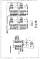
- derailleur 19 comprises cage 50, pulley wheel 30 and jockey wheel 29. Both the pulley wheel and the jockey wheel are arranged for rotation within the cage. Pulley wheel 30 rotates about mounting bolt 51, whereas jockey wheel 29 rotates about mounting bolt 36. Chain 18 engages both pulley wheels and is operatively arranged to rotate pulley wheel 30 in a counterclockwise direction and jockey wheel 29 in a clockwise direction when the chain is driven in a clockwise rotation by front sprocket 16.
- Jockey wheel 29 comprises a plurality of embedded magnets 29a, 29b, 29c, 29d, and 29e.
- the magnets are A1NiCo in composition and are equally spaced radially and angularly. Although five magnets are shown in the drawing, any number of magnets can be used. In fact, the attached software code for the invention is written for four equally spaced magnets.
- Speed sensor 22 comprises approximately 4000 turns of 40 gauge enamel coated wire, wound about a 0.125 inch diameter mild carbon steel dowel, which is then bent to form a U-shape. The winding has a resistance of approximately 200 ohms. Once the winding is made, it is potted in place with epoxy. As shown in Figures 2 and 3 , sensor 22 is mounted to bracket 50 by bolt 36. The body of the sensor may have an integral mounting bracket 38 or may be mounted using any standard mounting means known in the art. The sensor may be a proximity sensor such as a simple reed switch or some other type of sensor including, but not limited to, magnetic, inductive, or capacitive sensors.
- speed sensor 22 detects the movement of the magnets as pulley wheel 29 rotates.
- a magnet (or magnet ring containing multiple magnetic poles) can be mounted to one of the bicycle cranks.
- a speed sensor can be mounted to the bicycle's wheel. Crank speed, wheel speed, and a table of the bicycle's gear ratios then allows the calculation of chain speed.
- a magnet can be mounted to one of the cranks and the sensor can be a gear position indicator. This indicator would sense which of the bicycle's front sprockets is engaged with the chain.
- chain speed can be detected directly using a magnetic sensor, such as a variable reluctance (VR) sensor, a Hall Effect sensor or a magneto resistive sensor.
- a magnetic sensor such as a variable reluctance (VR) sensor, a Hall Effect sensor or a magneto resistive sensor. This method measures the linear movement of chain pins past the sensor to produce a signal that is representative of chain speed.
- the next step in determining power is to measure the vibration or tension of the drive chain.
- sensors that can be used to measure the vibration include but are not limited to variable reluctance sensors, Hall effect sensors, magneto resistive sensors, inductive, capacitive, optical and acoustic sensors. These sensors measure the frequency of vibration of the drive chain. In the case of a ferrous object, such as a bicycle chain moving past a magnetic-type sensor such as a variable sensor, an electric current is generated that is characteristic of the body's vibration.
- Such vibration results from excitation, or "plucking", which is a by-product of the normal operation of most devices, due to the inevitable friction and slight roughness of the tensioned body engaging with its drive or guide interfaces, such as rollers, sprockets, etc.
- this vibration is caused by the constant lateral and longitudinal accelerations of the bicycle, the motion induced by the individual rollers of the chain engaging and disengaging with the teeth of the drive sprockets, and the roughness of the surface on which the bicycle is being pedaled.
- the chain In a multi-speed bicycle the chain is capable of being shifted to a number of different sprockets at both the front and the rear. This causes the chain's position (relative to the bike) to change, but the overall length of the vibrating section remains essentially constant. This is because the chain engages drive sprockets at both ends of the tensioned section, and the position of the axis of rotation of these sprockets does not change.
- the constant length likewise means the mass of the vibrating section remains essentially constant.
- vibration sensor 24 is a variable reluctance sensor (VR sensor).
- the VR sensor comprises a 1.0" x 0.5" x 0.25" rectangular A1NiCO magnet 40 wrapped with approximately 3000 turns of 40 gauge copper enamel coated wire having a resistance of 1.049 ohms/foot. The total resistance of the coil is approximately 1000 ohms.
- the faces of the magnet are laminated with rectangular carbonite plastic sheets. The winding is potted into place with epoxy.
- the sensor is housed in a plastic casing 42 and is mounted to chain stay 23, such that its face 44 is in close proximity to the upper run of chain 18.
- the senor is mounted to the chain stay by means commonly known to those skilled in the art. so that face 44 of the sensor is directly below the upper run of the chain.
- the sensor is mounted at an angle so that face 44 of the sensor is at a constant distance from the chain irrespective of the sprockets being used by the rider. In a preferred embodiment, this angle is approximately 30 degrees.
- One method is to construct the sensor so that it combines the signals from two or more physical locations in such a way that the extraneous signal components cancel, or to use a sensor that has a relatively low response in the frequency band where the extraneous signal components occur.
- a second method is to use analog circuitry in the computer to filter out the frequency range of the extraneous components, which can be a fixed range, or a variable range controlled by the chain speed sensor.
- a third method is employed, in which the extraneous signal components are filtered out by means of digital signal processing, as described in the attached computer code for the DSP
- the overall length of the vibrating section of the chain remains essentially constant because the axes of rotation of the sprockets at both ends of the chain section do not change.
- the length of the section of the chain that vibrates does not remain exactly constant as various front and rear sprockets are selected. If the sprockets being used are differing sizes, the length of the vibrating length will be reduced. Depending on the level of accuracy desired in the power measuring system, this variation can be ignored, as in many circumstances, the error introduced will be insignificant. In those cases, it is sufficient to perform calculations using a constant value for the length of the vibrating section of the chain. This value can be either the distance between the centers of the sprockets, or that value reduced by a small amount.
- the sizes of the sprockets can be determined in various ways. If the shifting mechanism provides information as to what sprocket from a set has been selected, or if sensors are fitted to determine which sprockets the chain is actually on, then the sprocket sizes can be determined from a list of available sprockets.
- sprocket sizes can be determined without prior information about what sprockets are available.
- the rotational speeds of the sprockets are commonly measured on bicycles, with the speed of the front sprocket used to calculate cadence, and the speed of the rear sprocket (which is equivalent to the speed of the bicycle wheel) used to calculate bicycle speed.
- This determination of the sprocket is by means of integrating the chain speed over one rotation of the desired sprocket.
- the chain speed sensor will detect links of the chain directly, and the links can be counted over the period of one revolution of the sprocket in question.
- the links can be counted over two or more revolutions and divided by the number of revolutions.
- the size of the other sprocket may be obtained by multiplying the size of the first sprocket by the ratio in speeds between the two sprockets.
- the vibration sensor and the speed sensor are electrically connected to the computer module, which contains a signal processing unit.
- the module contains a liquid crystal display (LCD) and keyboard.
- LCD liquid crystal display
- the module is typically mounted on the handlebars for easy viewing during cycling, although it can be mounted in any convenient location.
- the computer module comprises a Texas Instruments TMS32OC3X Starter Kit, and an additional circuit board which comprises the peripheral interface circuit.
- the basic components of the TMS32OC3X DSP Starter Kit are the TMS32OC31 DSP, a TLC32040 analog interface circuit (AIC), expansion connectors, system clock, parallel printer port interface, and tri-color LED.
- block 100 represents vibration sensor 24.
- a signal with a voltage in the range of approximately 2 mV to 200 mV is produced.
- the relevant signal due to the frequency characteristic of the tension in the chain will be one component of this signal, but it may be accompanied by other signal components.
- the output signal from this sensor is fed to block 103, which represents the chain vibration amplifier.
- Amplifier 103 amplifies the chain vibration signal to a level that is appropriate for circuit components 104 and 105.
- the gain level can be adjusted two different ways, for four different gain settings. One adjustment is via jumper JP8, and the other is by means of the low gain signal, which is under control of the microprocessor.
- the amplitude of the signal from sensor 100 can vary, the dynamic range of circuit components 104 and 105 is high enough that the gain level should not need to be adjusted during operation; these two adjustments can be made once and left alone.
- the output of this section is an amplified version of its input, and is fed to circuit components 104 and 105. Alternatively, the output signal from this sensor is fed to block 104, which represents the low-pass filter.
- Circuit component 104 is a low-pass filter and component 105 is a 14 bit A/D converter. These two circuits are both contained in the Texas Instruments TLC32040 AIC part on the Starter Kit board. This part can be configured to convert its analog input to a 14-bit digital stream, sampled at 450 Hz, and it includes a Nyquist frequency low-pass filter to eliminate aliasing. The digital output of this section is read by the DSP (circuit component 110) for frequency calculations.
- DSP circuit component 110
- Component 101 contains chain speed sensor 22 as described previously.
- the sensor comprises a wire coil mounted on rear derailleur cage 50.
- Jockey wheel 29 of the derailleur contains embedded magnets 29a, 29b, 29c, 29d and 29e that induce a voltage in the coil as they pass by. This results in an oscillating signal whose frequency is directly proportional to the rotational speed of the jockey wheel, and consequently, to the linear speed of the chain that is driving the jockey pulley.
- the amplitude of this signal is typically in the range of 20 mV to 2V.
- This signal is fed to hysteresis circuit 102. It should be noted that, although five magnets are embedded in the jockey wheel in the preferred embodiment, any number of magnets can be embedded. Also, other means of measuring chain speed may be employed.
- Hysteresis circuit 102 converts the output signal of chain speed sensor 101 from its low voltage level to a TTL level that can be read by digital signal processor (DSP) 110.
- DSP digital signal processor
- Intermediate level information is not of interest-only the fundamental frequency due to the passing of each jockey wheel magnet is relevant.
- the circuit consists of a Schmitt Trigger, which has very high gain to "clip" the signal, and which has hysteresis to suppress any low-level noise that may be present in the signal. The result is a pulse train with each pulse corresponding to one of the jockey wheel magnets. This signal is input to digital signal processor 110.
- Digital signal processor (DSP) 110 and random access memory (RAM) 106 operate together to perform the power calculations.
- the DSP is a Texas Instruments Model No. TMS32OC31.
- the RAM contains the program code for this device (although such code could also be stored in a ROM chip connected to the DSP in an analogous manner).
- the DSP calculates power based on two inputs. The first is the signal from circuit component 102, which can be used to determine the linear speed of the chain (given the fixed values of how many magnets are on the jockey wheel, and how many teeth are on the jockey wheel).
- the second is the signal from circuit components 104 and 105, which can be used to determine the vibrational frequency of the chain, and in turn the tension of the chain (the speed of the chain, determined from the jockey wheel signal, is also used to assist in selecting the proper component from the output signal of circuit components 104 and 105).
- the tension of the chain is multiplied by the speed of the chain to give a result of the power transmitted through the chain at any instant. The method used to do this calculation is described fully in the attached computer code for the DSP.
- the signal is processed using a standard technique known to those skilled in the art including, but not limited to, Fast Fourier Transform, Discrete Fourier Transform, Fourier Transform, Zero-Crossing, 1-bit FFT with cosine/sine table look-up, wavelets, filter banks, FIR filters, IIR filters, adaptive filter techniques (including Least Mean Square Algorithm), adaptive interference cancelling, adaptive self-tuning filters, adaptive line enhancers, and gabor expansion.
- the frequency of the vibration can be determined by using "zero-crossing" algorithm, which measures the period of a sinusoid wave by realizing when the signal passes through the median voltage and measuring the time period between median voltage crossings.
- FFT Fast Fourier Transform
- Linear prediction algorithm (LPA) and auto regression method (AR) can be used to find more practical and more implementable solution in a microprocessor based technique.
- the chain speed variation signal can also be used. Because the chain speed reflects the power and force variation against the pedals and cranks this chain speed variation signal can be used as a reference signal form for the power variation signal form. And because these signals are closely correlating it is enough to calculate absolute power only sometimes so that the absolute power level of varying signal can be fixed. So it is necessary calculate and define the absolute power of force and tension only some (for example 1-2) times per one cadence cycle. That is because the power signal form is now known from the chain speed signal and some points are used to fix that signal to the absolute scale values.
- the speed of the elongate flexible member can be measured directly by using a speed sensor. In another preferred embodiment of the invention the speed is determined indirectly, for example by using cadence measurement. In said another embodiment the speed of the elongate flexible member is determined by using cadence signal, wheel speed and sprocket sizes or the ratio of sprocket sizes.
- Chain speed is calculated by counting the time between the rising edges of the jockey wheel signal.
- Memory 107 is a non-volatile memory chip, such as a serial EEROM.
- the DSP is operatively arranged to write and read data to and from memory 107.
- Memory 107 is used to store installation- specific information such as chain-line length and chain linear density.
- Circuit components 108 liquid crystal display (LCD)
- 109 keyboard/CPU
- 111 keyboard
- the DSP can send the calculated power value (or any other relevant information) to this CPU, which will display the information on the LCD. Key presses on the keyboard will result in information being sent to the DSP, which can respond with some appropriate action (e.g., changing the displayed power value from watts to horsepower.) Any suitable user interface can be implemented.
- These three components comprise a standard off-the-shelf unit manufactured and available by Bolton Engineering of Melrose, MA.
- the computer generates a signal representing the power output of the elongate flexible member to a external unit coupled to said computer, said external unit having a display for displaying the power output.
- Said external unit is the terminal referred above.
- the external unit coupled to said computer is a heart rate monitor having a display. Heart rate sensor measures the ECG of the bicycle user.
- Circuit component 112 is an optional RS232 interface, well known to those having ordinary skill in the art. This interface converts the TTL signal levels of the UART connected to the DSP into RS232 levels for communication with an external device such as a personal computer (PC). The DSP can use this interface to upload a series of saved power values to a host PC for analysis.
- PC personal computer
- Component 113 is a host PC.
- This PC is an external device which is not used in normal operation of the invention. It can be any sort of computer that can retrieve information from the power meter device for further processing. It would typically be connected to the power meter at the completion of a bicycle fide.
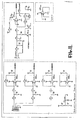
- FIGs 8-11 show electrical schematic diagrams of the peripheral interface circuit of the invention.
- the peripheral interface circuit connects the several peripheral devices (e.g., RAM, keyboard, display, etc.) of the invention to the microprocessor unit 110.
- the signal connections in the physical connectors of the electronic unit are shown in Fig. 8 and the connections of a keyboard and display in Fig. 9 and the connection of a memory unit in Fig. 10 .
- the connection of the sensors such as wheel speed sensor (WHEEL), cadence sensor (CADENCE), chain speed from the jockey wheel (JOCKEY) and vibration sensor (AUX) are shown in Fig. 11 to the Texas Instruments TMS32OC3X DSP Starter Kit board.
- WHEEL wheel speed sensor
- CADENCE cadence sensor
- JOCKEY jockey wheel
- AUX vibration sensor
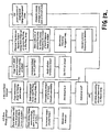
- Figure 12 is a flowchart of the computer code used to run the DSP in a preferred embodiment of the invention.
Landscapes
- Physics & Mathematics (AREA)
- General Physics & Mathematics (AREA)
- Chemical & Material Sciences (AREA)
- Engineering & Computer Science (AREA)
- Combustion & Propulsion (AREA)
- Measurement Of Mechanical Vibrations Or Ultrasonic Waves (AREA)
- Force Measurement Appropriate To Specific Purposes (AREA)
- Devices For Conveying Motion By Means Of Endless Flexible Members (AREA)
Applications Claiming Priority (4)
| Application Number | Priority Date | Filing Date | Title |
|---|---|---|---|
| US83374 | 1979-10-10 | ||
| US6235597P | 1997-10-15 | 1997-10-15 | |
| US62355P | 1997-10-15 | ||
| US09/083,374 US6199021B1 (en) | 1997-10-15 | 1998-05-22 | Method and apparatus for measuring power output of one powering a chain driven vehicle |
Publications (3)
| Publication Number | Publication Date |
|---|---|
| EP0909940A2 EP0909940A2 (en) | 1999-04-21 |
| EP0909940A3 EP0909940A3 (en) | 2000-03-22 |
| EP0909940B1 true EP0909940B1 (en) | 2013-02-20 |
Family
ID=26742167
Family Applications (1)
| Application Number | Title | Priority Date | Filing Date |
|---|---|---|---|
| EP98660105A Expired - Lifetime EP0909940B1 (en) | 1997-10-15 | 1998-10-15 | Method and apparatus for measuring power output and for measuring tension and vibrational frequency of a elongate flexible member |
Country Status (2)
| Country | Link |
|---|---|
| US (2) | US6199021B1 (e) |
| EP (1) | EP0909940B1 (e) |
Families Citing this family (48)
| Publication number | Priority date | Publication date | Assignee | Title |
|---|---|---|---|---|
| IT1310744B1 (it) * | 1999-11-26 | 2002-02-22 | Campagnolo Srl | Dispositivo sensore della posizione operativa di un sistema di cambiodi velocita' per bicicletta, e sistema di cambio di velocita' |
| IT1320286B1 (it) * | 2000-03-29 | 2003-11-26 | Campagnolo Srl | Sistema di controllo multiprocessore per cicli, ad esempio perbiciclette da competizione. |
| IT1320285B1 (it) * | 2000-03-29 | 2003-11-26 | Campagnolo Srl | Procedimento per il controllo del cambio di velocita' in un ciclo,relativo sistema e relativi componenti. |
| FI114042B (fi) * | 2000-08-25 | 2004-07-30 | Polar Electro Oy | Voimansiirtimen välittämän voiman mittaus |
| US6615676B2 (en) * | 2001-08-20 | 2003-09-09 | Honda Giken Kogyo Kabushiki Kaisha | Power steering belt tensioning apparatus and method |
| JP3860737B2 (ja) * | 2001-10-22 | 2006-12-20 | 株式会社シマノ | 自転車用リアディレーラ |
| DE10357169B4 (de) * | 2002-12-10 | 2015-01-29 | Schaeffler Technologies Gmbh & Co. Kg | Vorrichtung zum Erfassen der Geschwindigkeit des Umschlingungsmittels eines Kegelscheibenumschlingunggetriebes |
| GB0229027D0 (en) * | 2002-12-12 | 2003-01-15 | Paterson Colin | A device and method for measuring tensile stress in a tensioned, elongate, ferrous metal member |
| US20040183343A1 (en) * | 2003-01-30 | 2004-09-23 | Probst Paul C. | Seat technology |
| JP3953990B2 (ja) * | 2003-08-22 | 2007-08-08 | 株式会社キャットアイ | 計測装置およびセンサ装置 |
| TW200537901A (en) * | 2004-04-22 | 2005-11-16 | Yuh-Swu Hwang | Method and apparatus enable mobile phone capable of exercise measuring and workout support |
| US7257468B1 (en) * | 2005-03-04 | 2007-08-14 | George Costa | Apparatus and method for measuring dynamic parameters for a driven wheel |
| WO2007076068A2 (en) | 2005-12-22 | 2007-07-05 | Radow Scott B | Exercise device |
| US7599806B2 (en) * | 2006-03-17 | 2009-10-06 | Gunter Hauschildt | Portable power meter for calculating power applied to a pedal and crank arm based drive mechanism and a method of calculating the power |
| WO2007115073A2 (en) * | 2006-03-30 | 2007-10-11 | Saris Cycling Group, Inc. | Power meter for deriving elevational changes of a bicycle ride |
| US20070260483A1 (en) * | 2006-05-08 | 2007-11-08 | Marja-Leena Nurmela | Mobile communication terminal and method |
| US7833135B2 (en) * | 2007-06-27 | 2010-11-16 | Scott B. Radow | Stationary exercise equipment |
| AU2008274881B2 (en) | 2007-07-06 | 2010-06-24 | Mark Fisher | Crank arm with strain amplifier |
| US8641581B2 (en) * | 2007-08-30 | 2014-02-04 | Wattbike Ip Limited | Ergometric training device |
| US7806006B2 (en) * | 2007-11-08 | 2010-10-05 | Grand Valley State University | Bicycle torque measuring system |
| US7975561B1 (en) * | 2008-02-29 | 2011-07-12 | Saris Cycling Group, Inc. | Chain ring power sensor for a bicycle |
| US7792648B2 (en) * | 2008-06-19 | 2010-09-07 | Polar Electro Oy | System for determining pedalling effort of bicycle |
| US7775128B2 (en) * | 2008-09-04 | 2010-08-17 | Saris Cycling Group, Inc. | Cassette-based power meter |
| US8172045B2 (en) * | 2008-09-11 | 2012-05-08 | Ellcon National, Inc. | Remote hand brake |
| DE202009001463U1 (de) | 2009-02-06 | 2009-04-30 | Momes Llp | Vorrichtung zur Messung und Ermittlung der Kraft, der Momente und der Leistung an einer (Tret-)Kurbel |
| US8646796B2 (en) * | 2009-08-24 | 2014-02-11 | Alan Cote | Apparatus and method for extracting vibration data from a moving drive chain |
| US8336400B2 (en) * | 2009-11-24 | 2012-12-25 | Saris Cycling Group, Inc. | Rear hub power meter for a bicycle |
| WO2011063468A1 (en) | 2009-11-28 | 2011-06-03 | Entecho Pty Ltd | Cyclic cranked system method and related devices |
| US20120042725A1 (en) * | 2010-08-23 | 2012-02-23 | Alan Francis Cote | Method and Apparatus for Measuring Pedaling Dynamics of a Cyclist |
| US9921118B2 (en) | 2012-01-23 | 2018-03-20 | Foundation Fitness, LLC | Apparatus, system and method for power measurement at a crank axle and crank arm |
| US9417144B2 (en) * | 2011-01-21 | 2016-08-16 | Foundation Fitness, LLC | Apparatus, system and method for power measurement |
| TWM422528U (en) * | 2011-07-13 | 2012-02-11 | Xu Hong Jun | Transmission detection device for central axle |
| US9097598B2 (en) | 2011-07-18 | 2015-08-04 | Michael J. Grassi | Torque sensor |
| JP5607003B2 (ja) * | 2011-08-29 | 2014-10-15 | 株式会社シマノ | 自転車用センサの制御装置、自転車用センサの制御方法 |
| US9182300B2 (en) | 2012-10-10 | 2015-11-10 | Bosch Automotive Service Solutions Inc. | Method and system for measuring belt tension |
| WO2014199376A1 (en) * | 2013-06-10 | 2014-12-18 | Danimar Ltd. | Device and method for monitoring a chain parameter |
| TW201520980A (zh) | 2013-11-26 | 2015-06-01 | Nat Univ Chung Cheng | 可即時估算踏頻之視頻裝置 |
| EP2908097B1 (de) * | 2014-02-13 | 2016-11-16 | iwis antriebssysteme GmbH & Co. KG | Reluktanz-Kettensensor sowie Verfahren zur Messung der Kettenlängung |
| AU2016252283B2 (en) | 2015-04-20 | 2021-07-01 | John A. BALINT | Apparatus and method for increased realism of training on exercise machines |
| USD774429S1 (en) * | 2015-12-03 | 2016-12-20 | Helio Ascari | Bicycle brake lever |
| US10675913B2 (en) | 2016-06-24 | 2020-06-09 | Specialized Bicycle Components, Inc. | Bicycle wheel hub with power meter |
| TWI604992B (zh) * | 2016-06-28 | 2017-11-11 | Su Tai Inc | Method and apparatus for configuring a strain detector using a deformation signal generated by a measuring body due to pushing or pulling force |
| DE102016113016A1 (de) * | 2016-07-14 | 2018-01-18 | Lakeview Innovation Ltd. | Verfahren zur Steuerung eines elektrischen Hilfsantriebs sowie elektrischer Hilfsantrieb und Fahrzeug mit einem derartigen Hilfsantrieb |
| IT201600131281A1 (it) | 2016-12-27 | 2018-06-27 | Campagnolo Srl | Rilevatore per bicicletta |
| IT201600131314A1 (it) | 2016-12-27 | 2018-06-27 | Campagnolo Srl | Deragliatore elettronico wireless di bicicletta |
| CN107314845B (zh) * | 2017-07-03 | 2023-06-16 | 重庆理工大学 | 齿轮动态啮合力的测试方法 |
| WO2020172547A1 (en) | 2019-02-21 | 2020-08-27 | Radow Scott B | Exercise equipment with music synchronization |
| US11511826B2 (en) | 2019-12-09 | 2022-11-29 | Sram, Llc | Bicycle axle assembly including a power meter |
Family Cites Families (17)
| Publication number | Priority date | Publication date | Assignee | Title |
|---|---|---|---|---|
| US1107234A (en) | 1913-12-19 | 1914-08-11 | Irving Hill | Horse-power indicator and recorder. |
| US2618970A (en) | 1948-09-11 | 1952-11-25 | Morgan Construction Co | Determination of stresses in longitudinally traveling bodies |
| FR2308910A1 (fr) | 1975-04-21 | 1976-11-19 | Genzling Claude | Dispositif compteur-tachymetre integre pour bicyclette |
| DE2524605A1 (de) * | 1975-06-03 | 1976-12-23 | Heinz Peter Dipl Brandstetter | Vorrichtung zum messen von mechanischer arbeit und leistung |
| US4434801A (en) | 1980-04-30 | 1984-03-06 | Biotechnology, Inc. | Apparatus for testing physical condition of a self-propelled vehicle rider |
| JPS62261937A (ja) * | 1986-05-09 | 1987-11-14 | Mitsubishi Motors Corp | ベルト張力測定装置 |
| JPH01123116A (ja) * | 1987-11-06 | 1989-05-16 | Mitsubishi Motors Corp | ベルト張力測定装置 |
| GB2219657A (en) | 1988-06-09 | 1989-12-13 | Loughborough Consult Ltd | Method and apparatus for monitoring the tension in an elongate flexible member |
| US5027303A (en) * | 1989-07-17 | 1991-06-25 | Witte Don C | Measuring apparatus for pedal-crank assembly |
| JPH0734827B2 (ja) | 1989-10-07 | 1995-04-19 | コンビ株式会社 | 瞬発性パワー測定方法および装置 |
| US5167159A (en) | 1990-12-18 | 1992-12-01 | Lucking William M | Tension transducer |
| DE4201328A1 (de) | 1992-01-20 | 1993-07-22 | Teves Metallwaren Alfred | Sensor |
| DE4207530A1 (de) | 1992-03-10 | 1993-09-16 | Westfalia Becorit Ind Tech | Vorrichtung zur ermittlung der kettenspannung bei hobelkettenantrieben |
| US5545982A (en) | 1993-03-01 | 1996-08-13 | Vlakancic; Constant G. | Cycle computer system and protective cable |
| US5362886A (en) | 1993-10-12 | 1994-11-08 | Eli Lilly And Company | Asymmetric synthesis |
| US5456262A (en) * | 1993-11-01 | 1995-10-10 | Polar Electro Oy | Method for calculating a fitness index |
| DE4338819A1 (de) | 1993-11-13 | 1995-05-24 | Beno Heiss | Leistungsmesser |
-
1998
- 1998-05-22 US US09/083,374 patent/US6199021B1/en not_active Expired - Lifetime
- 1998-10-14 US US09/173,957 patent/US6356848B1/en not_active Expired - Lifetime
- 1998-10-15 EP EP98660105A patent/EP0909940B1/en not_active Expired - Lifetime
Also Published As
| Publication number | Publication date |
|---|---|
| EP0909940A3 (en) | 2000-03-22 |
| US6199021B1 (en) | 2001-03-06 |
| EP0909940A2 (en) | 1999-04-21 |
| US6356848B1 (en) | 2002-03-12 |
Similar Documents
| Publication | Publication Date | Title |
|---|---|---|
| EP0909940B1 (en) | Method and apparatus for measuring power output and for measuring tension and vibrational frequency of a elongate flexible member | |
| US7257468B1 (en) | Apparatus and method for measuring dynamic parameters for a driven wheel | |
| US5027303A (en) | Measuring apparatus for pedal-crank assembly | |
| US20120042725A1 (en) | Method and Apparatus for Measuring Pedaling Dynamics of a Cyclist | |
| US11162854B2 (en) | Apparatus, system and method for power measurement | |
| US7047817B2 (en) | Load measurement apparatus and methods utilizing torque sensitive link for pedal powered devices | |
| US4443008A (en) | Running type health promoting device | |
| EP2714501B1 (en) | Pedal assist sensor | |
| EP0527864B1 (en) | Bicycle electronic transmission control system | |
| CN101517353B (zh) | 用以测量反作用于移动车辆的总力的设备及其使用方法 | |
| US9150279B2 (en) | Method for measuring power in a bicycle | |
| US4463433A (en) | Pedalling efficiency indicator | |
| US8844377B2 (en) | System for a pedaling torque measurement device | |
| EP2058637A2 (en) | Bicycle torque measuring system | |
| JP5607003B2 (ja) | 自転車用センサの制御装置、自転車用センサの制御方法 | |
| US7792648B2 (en) | System for determining pedalling effort of bicycle | |
| US8955395B2 (en) | Magneto cyclist power sensor | |
| CN107107986B (zh) | 具有电驱动装置的车辆、尤其电动自行车,以及用于运行这种车辆的方法 | |
| US20210276654A1 (en) | Measuring device and measuring method for measuring bicycle pedaling frequency | |
| US8646796B2 (en) | Apparatus and method for extracting vibration data from a moving drive chain | |
| CN102968065A (zh) | 自行车用传感器的控制装置、自行车用传感器的控制方法 | |
| JP2000198481A (ja) | 自転車用コンピュ―タ及び走行情報を得るための方法 | |
| EP2532576A1 (en) | Cycle comprising an electric motor | |
| DE4431029A1 (de) | Drehmomentmeßwertgeber für Fahrradcomputer | |
| US20230302326A1 (en) | Method of controlling a force and/or resistance generator of an exercise apparatus |
Legal Events
| Date | Code | Title | Description |
|---|---|---|---|
| PUAI | Public reference made under article 153(3) epc to a published international application that has entered the european phase |
Free format text: ORIGINAL CODE: 0009012 |
|
| AK | Designated contracting states |
Kind code of ref document: A2 Designated state(s): CH DE ES FI FR GB IT LI NL |
|
| AX | Request for extension of the european patent |
Free format text: AL;LT;LV;MK;RO;SI |
|
| PUAL | Search report despatched |
Free format text: ORIGINAL CODE: 0009013 |
|
| AK | Designated contracting states |
Kind code of ref document: A3 Designated state(s): AT BE CH CY DE DK ES FI FR GB GR IE IT LI LU MC NL PT SE |
|
| AX | Request for extension of the european patent |
Free format text: AL;LT;LV;MK;RO;SI |
|
| 17P | Request for examination filed |
Effective date: 20000821 |
|
| AKX | Designation fees paid |
Free format text: CH DE ES FI FR GB IT LI NL |
|
| 17Q | First examination report despatched |
Effective date: 20040602 |
|
| GRAC | Information related to communication of intention to grant a patent modified |
Free format text: ORIGINAL CODE: EPIDOSCIGR1 |
|
| GRAP | Despatch of communication of intention to grant a patent |
Free format text: ORIGINAL CODE: EPIDOSNIGR1 |
|
| GRAJ | Information related to disapproval of communication of intention to grant by the applicant or resumption of examination proceedings by the epo deleted |
Free format text: ORIGINAL CODE: EPIDOSDIGR1 |
|
| GRAP | Despatch of communication of intention to grant a patent |
Free format text: ORIGINAL CODE: EPIDOSNIGR1 |
|
| GRAS | Grant fee paid |
Free format text: ORIGINAL CODE: EPIDOSNIGR3 |
|
| RAP1 | Party data changed (applicant data changed or rights of an application transferred) |
Owner name: CC KINETICS, INC. |
|
| GRAP | Despatch of communication of intention to grant a patent |
Free format text: ORIGINAL CODE: EPIDOSNIGR1 |
|
| GRAA | (expected) grant |
Free format text: ORIGINAL CODE: 0009210 |
|
| AK | Designated contracting states |
Kind code of ref document: B1 Designated state(s): CH DE ES FI FR GB IT LI NL |
|
| REG | Reference to a national code |
Ref country code: GB Ref legal event code: FG4D |
|
| REG | Reference to a national code |
Ref country code: CH Ref legal event code: EP |
|
| REG | Reference to a national code |
Ref country code: DE Ref legal event code: R096 Ref document number: 69842962 Country of ref document: DE Effective date: 20130418 |
|
| REG | Reference to a national code |
Ref country code: NL Ref legal event code: VDEP Effective date: 20130220 |
|
| PG25 | Lapsed in a contracting state [announced via postgrant information from national office to epo] |
Ref country code: ES Free format text: LAPSE BECAUSE OF FAILURE TO SUBMIT A TRANSLATION OF THE DESCRIPTION OR TO PAY THE FEE WITHIN THE PRESCRIBED TIME-LIMIT Effective date: 20130531 |
|
| PG25 | Lapsed in a contracting state [announced via postgrant information from national office to epo] |
Ref country code: FI Free format text: LAPSE BECAUSE OF FAILURE TO SUBMIT A TRANSLATION OF THE DESCRIPTION OR TO PAY THE FEE WITHIN THE PRESCRIBED TIME-LIMIT Effective date: 20130220 |
|
| PG25 | Lapsed in a contracting state [announced via postgrant information from national office to epo] |
Ref country code: NL Free format text: LAPSE BECAUSE OF FAILURE TO SUBMIT A TRANSLATION OF THE DESCRIPTION OR TO PAY THE FEE WITHIN THE PRESCRIBED TIME-LIMIT Effective date: 20130220 |
|
| PLBE | No opposition filed within time limit |
Free format text: ORIGINAL CODE: 0009261 |
|
| STAA | Information on the status of an ep patent application or granted ep patent |
Free format text: STATUS: NO OPPOSITION FILED WITHIN TIME LIMIT |
|
| PG25 | Lapsed in a contracting state [announced via postgrant information from national office to epo] |
Ref country code: IT Free format text: LAPSE BECAUSE OF FAILURE TO SUBMIT A TRANSLATION OF THE DESCRIPTION OR TO PAY THE FEE WITHIN THE PRESCRIBED TIME-LIMIT Effective date: 20130220 |
|
| 26N | No opposition filed |
Effective date: 20131121 |
|
| REG | Reference to a national code |
Ref country code: DE Ref legal event code: R097 Ref document number: 69842962 Country of ref document: DE Effective date: 20131121 |
|
| REG | Reference to a national code |
Ref country code: CH Ref legal event code: PL |
|
| GBPC | Gb: european patent ceased through non-payment of renewal fee |
Effective date: 20131015 |
|
| REG | Reference to a national code |
Ref country code: DE Ref legal event code: R119 Ref document number: 69842962 Country of ref document: DE Effective date: 20140501 |
|
| PG25 | Lapsed in a contracting state [announced via postgrant information from national office to epo] |
Ref country code: GB Free format text: LAPSE BECAUSE OF NON-PAYMENT OF DUE FEES Effective date: 20131015 Ref country code: LI Free format text: LAPSE BECAUSE OF NON-PAYMENT OF DUE FEES Effective date: 20131031 Ref country code: CH Free format text: LAPSE BECAUSE OF NON-PAYMENT OF DUE FEES Effective date: 20131031 |
|
| REG | Reference to a national code |
Ref country code: FR Ref legal event code: ST Effective date: 20140630 |
|
| PG25 | Lapsed in a contracting state [announced via postgrant information from national office to epo] |
Ref country code: DE Free format text: LAPSE BECAUSE OF NON-PAYMENT OF DUE FEES Effective date: 20140501 Ref country code: FR Free format text: LAPSE BECAUSE OF NON-PAYMENT OF DUE FEES Effective date: 20131031 |