EP0909667B1 - Dispositif auxiliaire pour le montage et le démontage d'un pneu - Google Patents
Dispositif auxiliaire pour le montage et le démontage d'un pneu Download PDFInfo
- Publication number
- EP0909667B1 EP0909667B1 EP98203321A EP98203321A EP0909667B1 EP 0909667 B1 EP0909667 B1 EP 0909667B1 EP 98203321 A EP98203321 A EP 98203321A EP 98203321 A EP98203321 A EP 98203321A EP 0909667 B1 EP0909667 B1 EP 0909667B1
- Authority
- EP
- European Patent Office
- Prior art keywords
- lever
- swivel arm
- pressing element
- exert
- bead
- Prior art date
- Legal status (The legal status is an assumption and is not a legal conclusion. Google has not performed a legal analysis and makes no representation as to the accuracy of the status listed.)
- Expired - Lifetime
Links
- 239000011324 bead Substances 0.000 claims description 14
- 230000008878 coupling Effects 0.000 claims description 12
- 238000010168 coupling process Methods 0.000 claims description 12
- 238000005859 coupling reaction Methods 0.000 claims description 12
- 210000000078 claw Anatomy 0.000 description 1
- 230000004048 modification Effects 0.000 description 1
- 238000012986 modification Methods 0.000 description 1
- 210000002445 nipple Anatomy 0.000 description 1
Images


Classifications
-
- B—PERFORMING OPERATIONS; TRANSPORTING
- B60—VEHICLES IN GENERAL
- B60C—VEHICLE TYRES; TYRE INFLATION; TYRE CHANGING; CONNECTING VALVES TO INFLATABLE ELASTIC BODIES IN GENERAL; DEVICES OR ARRANGEMENTS RELATED TO TYRES
- B60C25/00—Apparatus or tools adapted for mounting, removing or inspecting tyres
- B60C25/01—Apparatus or tools adapted for mounting, removing or inspecting tyres for removing tyres from or mounting tyres on wheels
- B60C25/05—Machines
- B60C25/132—Machines for removing and mounting tyres
Definitions
- This invention relates to an auxiliary device for fitting and removing a tire from a wheel rim, plus especially cars, motorcycles, etc.
- the invention relates to a device for use to assist the assembly and disassembly in the case of very rigid tires, such as low profile tires.
- Certain tires more specifically size tires low, have the disadvantage that the sides are very rigid and heels cannot be pushed into said hollow without the aid of an additional force.
- An auxiliary device for exerting such force additional is known from document EP 0.649.763 and comprises a lever provided with a pressure element, this lever being removable so it can be mounted on either of two supports, thus allowing said element to pressure can be supported either on the heel and / or flank lower, either on the bead and / or upper sidewall of the tire.
- This known device therefore has the disadvantage that it is necessary move said lever from one support to another according to the heel and / or the flank in question, which is impractical.
- the invention contemplates a device which does not have this disadvantage.
- the invention relates to an auxiliary device for fitting and removing a tire from a wheel, cooperating with an apparatus comprising a rotary table provided with elements to tighten the rim, and a tool which can be positioned at the top edge of the rim mounted on the table, said auxiliary device comprising a lever carrying at least one pressure element allowing to exert pressure on the heel and / or flank of the tire, characterized in that the lever is fixed in a mobile way, especially in a way swivel, at a fixed support relative to the device, at using a unique coupling system allowing move the lever between a first position in which the pressure element can exert pressure on one bead or sidewall of a tire surrounding a mounted rim on the table of the above-mentioned device, and a second position in which the pressure element can exert a pressure on the other bead and / or sidewall of said tire.
- the coupling system comprises an arm swivel pivotally attached to the support, said lever carrying the pressure member being coupled in turn to swivel to the swivel arm.
- the coupling system can be constructed in such a way so that the angle of the rod relative to the table is different for said two positions of the sink.
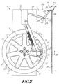
- the invention relates to an auxiliary device 1 for assist in mounting a tire 2 on a rim 3 or removing a tire 2 from a rim 3, this device 1 cooperating with a traditional device 4 for mounting and removing tires.
- This device 4 mainly consists of a frame 5; a rotary table 6 mounted on this frame 5, provided with elements clamping 7, more particularly claws, allowing to fix the rim 3 of a wheel 8 on this table 6; and an column 9 carrying a tool 10 which can be positioned at level of the upper edge 11 of the rim 3, this tool 10 comprising in known manner a part 12 for receiving a lever 13 which can be inserted between the upper edge 11 and the tire 2 and a guide element 14 for the tire 2.
- the device 1 is substantially constituted by a lever 15 carrying a pressure element 16, this lever 15 being pivotally attached to a support 17 which is fixed to the frame 5 of the device 4 using a system single coupling 18 allowing movement of the lever 15 between two positions, i.e. a first position in which the pressure element 16 can exert a pressure on the upper bead 19 of the tire 2 surrounding the rim 3 mounted on the table 6 as shown in Figures 6 and 7 and a second position in which the pressure element 16 can exert pressure on the lower bead 20 of said tire 2.
- the pressure element 16 is a sphere fixed in a point intermediate to lever 15 using a rod 21.
- Said support 17 is constituted by a horizontal fixed arm directed obliquely forward.
- the coupling system 18 is constituted in the example described by a pivoting arm 22, one end of which 23 is rotatably fixed about an axis 24 located at the free end of the support 17 in the extension of this support 17, the lever 15 being coupled to the other end 25 of the pivoting arm 22 by means of an articulated coupling 26.
- the articulated coupling 26 comprises two axes of rotation, a first axis being formed by a pin 27 fixed to the end of the pivoting arm 22 and rotatable in an element 28 bearing on two opposite faces a stud 29 or 30, these nipples 29-30 forming the second axis and being articulated in the fork 31 provided for this purpose at the end of the lever 15.
- the axis formed by the spindle 27 is not parallel to the axis horizontal 24 but at an angle to the plane of rotation of the pivoting arm 22.
- the axis formed by the pins 29-30 is practically perpendicular to the above axis.
- the free end of the support 17 has two stops 32-33 in the form of rods for the pivoting arm 22, these stops 32-33 being positioned so as to limit movement of the pivoting arm 22 at an angle between 90 and 180 degrees and especially between a position in which the latter is directed upwards, as shown in lines interrupted in Figures 4 and 5 and a position in which it is directed obliquely downwards, as shown in solid lines.
- the pressure element 16 is located more and more forward or backward depending on whether the pivoting arm 22 is in contact with the stop 32 or 33.
- the element of pressure 16 can act on the lower heel 20 to one optimal location, while the pressure element 16 can act on the upper heel 19 without hindering the use of tool 10.
- the device 1 and in particular the pressure element 16 are used similarly when mounting a tire 2.
- the lever 15 carries two pressure elements, one of the pressure that can exert pressure on the heel 19 to one position of the lever 15, the other pressure element can exert pressure on the other heel 20 to the other position of the lever 15.
- the element of pressure 16 can possibly push on a side of the tire 2.
Landscapes
- Engineering & Computer Science (AREA)
- Mechanical Engineering (AREA)
- Tires In General (AREA)
Description
Claims (9)
- Dispositif auxiliaire pour le montage et le démontage d'un pneu (2) d'une roue (8), coopérant avec un appareil (4) comportant une table rotative (6) pourvue d'éléments (7) à serrer la jante (3) de la roue (8), et un outil (10) qui peut être positionné au niveau du bord supérieur de la jante (3) montée sur la table (6), ledit dispositif auxiliaire comportant un levier (15) portant au moins un élément de pression (16) permettant d'exercer une pression sur le talon (19-20) et/ou flanc du pneu (2), caractérisé en ce que le levier (15) est fixé d'une manière mobile, plus particulièrement d'une manière pivotante, à un appui (17) fixe par rapport à l'appareil (4), à l'aide d'un système d'accouplement unique (18) permettant de mouvoir le levier (15) entre une première position dans laquelle. l'élément de pression (16) peut exercer une pression sur l'un des talons (19-20) ou flancs d'un pneu (2) entourant une jante (3) montée sur la table (6) de l'appareil (4) susdit, et une deuxième position dans laquelle l'élément de pression (16) peut exercer une pression sur l'autre talon et/ou flanc dudit pneu (2).
- Dispositif selon la revendication 1, caractérisé en ce que l'élément de pression (16) est monté à un point intermédiaire sur le levier (15) à l'aide d'une tige (21).
- Dispositif selon la revendication 1 ou 2, caractérisé en ce que le système d'accouplement (18) comprend un bras pivotant (22) fixé de manière pivotante à l'appui (17), ledit levier (15) portant l'élément de pression (16) étant accouplé à son tour de manière pivotante au bras pivotant (22).
- Dispositif selon la revendication 3, caractérisé en ce que le levier (15) est accouplé au bras pivotant (22) au moyen d'un accouplement articulé (26).
- Dispositif selon l'une quelconque des revendications 3 à 4, caractérisé en ce qu'il est pourvu de deux arrêts (32-33) limitant le mouvement de bras pivotant (22) entre deux positions, une position dans laquelle le bras pivotant (22) est dirigé vers le haut et une position dans laquelle le bras pivotant (22) est dirigé obliquement vers le bas.
- Dispositif selon la revendication 5, caractérisé en ce que les arrêts (32-33) sont situés de telle manière que l'élément de pression (16) est localisé différemment au contour défini par le talon (19-20) selon que le bras pivotant (22) est en l'une ou l'autre des positions susdites, afin de ne pas gêner l'utilisation de l'outil (10).
- Dispositif selon la revendication 2, caractérisé en ce que le système d'accouplement (18) est construit de telle façon que l'angle de la tige (21) par rapport à la table rotative (6) est différent pour lesdites deux positions de levier (15).
- Dispositif selon la revendication 2 et l'une quelconque des revendications 3 à 6, caractérisé en ce que le levier (15) portant l'élément de pression (16) est accouplé au bras pivotant (22) de manière pivotante autour d'un axe de rotation situé sous un angle par rapport au plan de rotation du bras pivotant (22).
- Dispositif selon l'une ou l'autre des revendications précédentes, caractérisé en ce que le levier (15) porte deux éléments de pression, une des éléments de pression pouvant exercer une pression sur un talon (19) ou flanc pour une position du levier (15), l'autre élément de pression pouvant exercer une pression sur l'autre talon (20) ou flanc pour l'autre position du levier (15).
Applications Claiming Priority (2)
| Application Number | Priority Date | Filing Date | Title |
|---|---|---|---|
| BE9700819 | 1997-10-14 | ||
| BE9700819A BE1011494A3 (fr) | 1997-10-14 | 1997-10-14 | Dispositif auxiliaire pour le montage et le demontage d'un pneu. |
Publications (2)
| Publication Number | Publication Date |
|---|---|
| EP0909667A1 EP0909667A1 (fr) | 1999-04-21 |
| EP0909667B1 true EP0909667B1 (fr) | 2002-01-09 |
Family
ID=3890773
Family Applications (1)
| Application Number | Title | Priority Date | Filing Date |
|---|---|---|---|
| EP98203321A Expired - Lifetime EP0909667B1 (fr) | 1997-10-14 | 1998-10-01 | Dispositif auxiliaire pour le montage et le démontage d'un pneu |
Country Status (4)
| Country | Link |
|---|---|
| US (1) | US6182735B1 (fr) |
| EP (1) | EP0909667B1 (fr) |
| BE (1) | BE1011494A3 (fr) |
| DE (1) | DE69803420T2 (fr) |
Families Citing this family (13)
| Publication number | Priority date | Publication date | Assignee | Title |
|---|---|---|---|---|
| US6684927B1 (en) | 2000-10-24 | 2004-02-03 | Summit Tool Company | Tire mounting tool |
| US6588479B1 (en) * | 2000-10-24 | 2003-07-08 | Summit Tool Company | Tire working tool |
| ITMO20030299A1 (it) * | 2003-11-04 | 2005-05-05 | Sicam S R L Societa Unipersonale | Attrezzo per macchine smontagomme per il montaggio e lo smontaggio di pneumatici di ruote per veicoli |
| US6907913B1 (en) * | 2003-11-12 | 2005-06-21 | C & J Industries, Inc. | Tire mounting device and method |
| US7267155B2 (en) * | 2005-03-01 | 2007-09-11 | Brahler Ii Richard W | Tire working tool |
| US7832449B2 (en) * | 2005-06-30 | 2010-11-16 | Robert Kenjiro Levin | Tire mounting and dismounting methods and systems |
| BE1016805A3 (fr) | 2005-10-12 | 2007-07-03 | Quesne Bertrand Du | |
| US7156141B1 (en) | 2006-05-16 | 2007-01-02 | Summit Tool Company | Tire demounting tool |
| ITMC20060117A1 (it) * | 2006-09-11 | 2008-03-12 | Corghi Spa | Dispositivo accessorio per macchine smontagomme, atto ad agevolare lo smontaggio del pneumatico. |
| ATE544619T1 (de) | 2009-10-08 | 2012-02-15 | Quesne Bertrand Du | Maschine zur radmontage und -demontage |
| ITMO20100202A1 (it) * | 2010-07-05 | 2012-01-06 | Teco Srl | Attrezzo ausiliario per macchine smontagomme |
| ITMO20130008A1 (it) * | 2013-01-17 | 2014-07-18 | Giuliano Group Spa | Macchina per lo smontaggio ed il montaggio di pneumatici di ruote per veicoli |
| CN110549801B (zh) * | 2019-09-19 | 2020-06-26 | 泉州燕群广告有限公司 | 一种用于公路车的快速自动拆装管胎装置 |
Family Cites Families (2)
| Publication number | Priority date | Publication date | Assignee | Title |
|---|---|---|---|---|
| DE9101930U1 (fr) * | 1991-02-19 | 1991-06-06 | Stahlgruber Otto Gruber Gmbh & Co, 8000 Muenchen, De | |
| BE1007626A6 (fr) | 1993-10-22 | 1995-08-29 | Quesne Francis Du | Dispositif pour assister efficacement les operations de montage et de demontage d'un pneu d'une jante de roue. |
-
1997
- 1997-10-14 BE BE9700819A patent/BE1011494A3/fr active
-
1998
- 1998-10-01 DE DE69803420T patent/DE69803420T2/de not_active Expired - Lifetime
- 1998-10-01 EP EP98203321A patent/EP0909667B1/fr not_active Expired - Lifetime
- 1998-10-13 US US09/169,957 patent/US6182735B1/en not_active Expired - Lifetime
Also Published As
| Publication number | Publication date |
|---|---|
| DE69803420T2 (de) | 2002-08-08 |
| EP0909667A1 (fr) | 1999-04-21 |
| BE1011494A3 (fr) | 1999-10-05 |
| DE69803420D1 (de) | 2002-02-28 |
| US6182735B1 (en) | 2001-02-06 |
Similar Documents
| Publication | Publication Date | Title |
|---|---|---|
| EP0909667B1 (fr) | Dispositif auxiliaire pour le montage et le démontage d'un pneu | |
| EP0387460A1 (fr) | Appareil pour le démontage et le montage de soupapes et pour le rectifiage de sièges de soupape | |
| EP2414199B1 (fr) | Gabarit de positionnement et procede de mise en place d'un pare-chocs avant de vehicule automobile | |
| EP1775148B1 (fr) | Outillage auxiliaire pour le montage d'un pneu sur une jante | |
| EP0001855A1 (fr) | Dispositif pour serrer une roue de motocyclette dont il y a lieu d'enlever un pneu ou sur laquelle un pneu doit être monté | |
| EP1652761A2 (fr) | Dispositif universel d'arrimage d'au moins un accessoire à une motocyclette | |
| FR2794413A3 (fr) | Appareil roulant, tel qu'une poussette, un deambulateur pour personne handicapee et un fauteuil roulant | |
| CH599865A5 (en) | Tyre removal and fitting machine | |
| BE1007626A6 (fr) | Dispositif pour assister efficacement les operations de montage et de demontage d'un pneu d'une jante de roue. | |
| EP0278896A1 (fr) | Dispositif de chaîne à neige auxiliaire pour véhicule routier | |
| CA2291872C (fr) | Procede de montage d'un pneumatique sur une jante et dispositif pour la mise en oeuvre d'une etape de ce procede | |
| EP2308699B1 (fr) | Machine de montage et de démontage de pneus | |
| EP1488848B1 (fr) | Système de maintien élastique d'un récipient en regard d'une tête de mélange d'un mélangeur | |
| EP0368385B1 (fr) | Dispositif pour ajuster l'outil d'un appareil de montage et de démontage de pneus d'automobiles | |
| EP0722849B1 (fr) | Roulette pivotante à blocage directionnel à couple réglable | |
| EP0032759A2 (fr) | Dispositif pour la manipulation de roues et de pneus dans un appareil pour le montage et le démontage de pneus | |
| FR2992624A1 (fr) | Systeme de fixation d'un accessoire sur un velo | |
| EP0006673B1 (fr) | Mécanisme pour le réglage de la position du bras porte-outil d'un dispositif pour monter et démonter un pneu sur une jante de roue | |
| EP0006672B1 (fr) | Dispositif pour le montage et le démontage d'un pneu sur une jante de roue | |
| EP3256225B1 (fr) | Dispositif de maintien pour bicyclette et ensemble dedie a l'entrainement sur bicyclette en position stationnaire | |
| FR2675762A1 (fr) | Adaptateur pour immobilisation d'une roue de type galette dans un logement de roue normale. | |
| FR2578469A1 (fr) | Dispositif pour le montage et le demontage d'une meule sur une tete de polissage | |
| FR2711422A1 (fr) | Dispositif de fixation d'appareil sur jante de roue de véhicule. | |
| WO2023062321A1 (fr) | Installation pour le maintien d'un engin roulant a deux ou trois roues en vue d'une intervention sur ledit engin | |
| FR2559436A1 (fr) | Remorque pour la mise hors d'eau et le transport des bateaux, notamment des bateaux de plaisance |
Legal Events
| Date | Code | Title | Description |
|---|---|---|---|
| PUAI | Public reference made under article 153(3) epc to a published international application that has entered the european phase |
Free format text: ORIGINAL CODE: 0009012 |
|
| AK | Designated contracting states |
Kind code of ref document: A1 Designated state(s): DE FR GB IT |
|
| AX | Request for extension of the european patent |
Free format text: AL;LT;LV;MK;RO;SI |
|
| 17P | Request for examination filed |
Effective date: 19990628 |
|
| AKX | Designation fees paid |
Free format text: DE FR GB IT |
|
| GRAG | Despatch of communication of intention to grant |
Free format text: ORIGINAL CODE: EPIDOS AGRA |
|
| GRAG | Despatch of communication of intention to grant |
Free format text: ORIGINAL CODE: EPIDOS AGRA |
|
| GRAH | Despatch of communication of intention to grant a patent |
Free format text: ORIGINAL CODE: EPIDOS IGRA |
|
| 17Q | First examination report despatched |
Effective date: 20010530 |
|
| GRAH | Despatch of communication of intention to grant a patent |
Free format text: ORIGINAL CODE: EPIDOS IGRA |
|
| GRAA | (expected) grant |
Free format text: ORIGINAL CODE: 0009210 |
|
| REG | Reference to a national code |
Ref country code: GB Ref legal event code: IF02 |
|
| AK | Designated contracting states |
Kind code of ref document: B1 Designated state(s): DE FR GB IT |
|
| REF | Corresponds to: |
Ref document number: 69803420 Country of ref document: DE Date of ref document: 20020228 |
|
| GBT | Gb: translation of ep patent filed (gb section 77(6)(a)/1977) |
Effective date: 20020406 |
|
| PLBE | No opposition filed within time limit |
Free format text: ORIGINAL CODE: 0009261 |
|
| STAA | Information on the status of an ep patent application or granted ep patent |
Free format text: STATUS: NO OPPOSITION FILED WITHIN TIME LIMIT |
|
| 26N | No opposition filed | ||
| PG25 | Lapsed in a contracting state [announced via postgrant information from national office to epo] |
Ref country code: IT Free format text: LAPSE BECAUSE OF NON-PAYMENT OF DUE FEES Effective date: 20051001 |
|
| PGRI | Patent reinstated in contracting state [announced from national office to epo] |
Ref country code: IT Effective date: 20110616 |
|
| PGFP | Annual fee paid to national office [announced via postgrant information from national office to epo] |
Ref country code: DE Payment date: 20141021 Year of fee payment: 17 Ref country code: GB Payment date: 20141029 Year of fee payment: 17 Ref country code: FR Payment date: 20141031 Year of fee payment: 17 |
|
| PGFP | Annual fee paid to national office [announced via postgrant information from national office to epo] |
Ref country code: IT Payment date: 20141025 Year of fee payment: 17 |
|
| REG | Reference to a national code |
Ref country code: DE Ref legal event code: R119 Ref document number: 69803420 Country of ref document: DE |
|
| GBPC | Gb: european patent ceased through non-payment of renewal fee |
Effective date: 20151001 |
|
| PG25 | Lapsed in a contracting state [announced via postgrant information from national office to epo] |
Ref country code: GB Free format text: LAPSE BECAUSE OF NON-PAYMENT OF DUE FEES Effective date: 20151001 Ref country code: DE Free format text: LAPSE BECAUSE OF NON-PAYMENT OF DUE FEES Effective date: 20160503 Ref country code: IT Free format text: LAPSE BECAUSE OF NON-PAYMENT OF DUE FEES Effective date: 20151001 |
|
| REG | Reference to a national code |
Ref country code: FR Ref legal event code: ST Effective date: 20160630 |
|
| PG25 | Lapsed in a contracting state [announced via postgrant information from national office to epo] |
Ref country code: FR Free format text: LAPSE BECAUSE OF NON-PAYMENT OF DUE FEES Effective date: 20151102 |