EP0909666A2 - Reifen mit Gleitschutzeigenschaften - Google Patents
Reifen mit Gleitschutzeigenschaften Download PDFInfo
- Publication number
- EP0909666A2 EP0909666A2 EP98307491A EP98307491A EP0909666A2 EP 0909666 A2 EP0909666 A2 EP 0909666A2 EP 98307491 A EP98307491 A EP 98307491A EP 98307491 A EP98307491 A EP 98307491A EP 0909666 A2 EP0909666 A2 EP 0909666A2
- Authority
- EP
- European Patent Office
- Prior art keywords
- air
- tire
- air chambers
- tread
- evacuation tube
- Prior art date
- Legal status (The legal status is an assumption and is not a legal conclusion. Google has not performed a legal analysis and makes no representation as to the accuracy of the status listed.)
- Granted
Links
Images


Classifications
-
- B—PERFORMING OPERATIONS; TRANSPORTING
- B60—VEHICLES IN GENERAL
- B60C—VEHICLE TYRES; TYRE INFLATION; TYRE CHANGING; CONNECTING VALVES TO INFLATABLE ELASTIC BODIES IN GENERAL; DEVICES OR ARRANGEMENTS RELATED TO TYRES
- B60C11/00—Tyre tread bands; Tread patterns; Anti-skid inserts
- B60C11/14—Anti-skid inserts, e.g. vulcanised into the tread band
- B60C11/16—Anti-skid inserts, e.g. vulcanised into the tread band of plug form, e.g. made from metal, textile
- B60C11/1606—Anti-skid inserts, e.g. vulcanised into the tread band of plug form, e.g. made from metal, textile retractable plug
- B60C11/1612—Anti-skid inserts, e.g. vulcanised into the tread band of plug form, e.g. made from metal, textile retractable plug actuated by fluid, e.g. using fluid pressure difference
-
- B—PERFORMING OPERATIONS; TRANSPORTING
- B60—VEHICLES IN GENERAL
- B60C—VEHICLE TYRES; TYRE INFLATION; TYRE CHANGING; CONNECTING VALVES TO INFLATABLE ELASTIC BODIES IN GENERAL; DEVICES OR ARRANGEMENTS RELATED TO TYRES
- B60C11/00—Tyre tread bands; Tread patterns; Anti-skid inserts
-
- Y—GENERAL TAGGING OF NEW TECHNOLOGICAL DEVELOPMENTS; GENERAL TAGGING OF CROSS-SECTIONAL TECHNOLOGIES SPANNING OVER SEVERAL SECTIONS OF THE IPC; TECHNICAL SUBJECTS COVERED BY FORMER USPC CROSS-REFERENCE ART COLLECTIONS [XRACs] AND DIGESTS
- Y10—TECHNICAL SUBJECTS COVERED BY FORMER USPC
- Y10T—TECHNICAL SUBJECTS COVERED BY FORMER US CLASSIFICATION
- Y10T152/00—Resilient tires and wheels
- Y10T152/10—Tires, resilient
- Y10T152/10279—Cushion
Definitions
- the present invention relates to an automobile tire useful throughout all seasons, and particularly to a tire with non-slip properties which is capable of providing an anti-skidding function during a snowfall and eliminating the need for being replaced with a nonskid tire.
- the present invention provides a tire characterized in that air chambers defined by peripheral walls are formed in the tread of the tire, and an air supply and evacuation tube is disposed inside of the tread, the air supply and evacuation tube being connected with the air chambers, the tread surface having bosses extending outwardly therefrom at locations corresponding to those portions of the peripheral walls of the air chambers facing the tread surface, the bosses allowing portions of the tread to be bulged from and depressed into the tread surface depending on air pressure in the air chambers.
- on-off valve means may be provided in connecting portions between the air chambers and the air supply and evacuation tube or in the air supply and evacuation tube where the air supply and evacuation tube leads into the air chambers.
- the on-off valve means may comprise bladder means adapted to be inflated when it is filled with air to thereby seal the air chambers, the air supply and evacuation tube disposed inside of the tread being connected with the air chambers.
- the bosses on the tread surface side wall portion defining the air chambers are caused to project from the tread surface by filling the air chambers with air through the air supply and evacuation tube whereby the projected bosses may perform the anti-skidding function.
- bosses are parts of the tread, there is no possibility of the bosses abrading the road surface or generating noise. Even if the car happens to encounter a snowless road, it may continue to run while the bosses are maintained in their projected position without the need for the operation for collapsing the bosses.
- the tire may be switched to the normal tire mode of use by evacuating the air chambers of the air to allow the bosses to collapse into the air chambers.
- the on-off valve means is opened to introduce air into the air chambers until they are filled with air, whereupon the valve means is closed to seal off the air chambers. In this state, even if the air chambers are subjected to pressure by contacting the ground, the on-off valve means prevents the air in the air chambers from flowing back into the air supply and evacuation tube to thereby prevent collapsing of the bosses into the air chambers due to a pressure drop in the chambers.
- Fig. 1 is a fragmentary front view, partly in radial cross-section, illustrating a first embodiment of the tire having the anti-skidding function according to the invention as set forth in claim 1;
- Fig. 2 is an enlarged fragmentary circumferential cross-sectional view illustrating the tire shown in Fig. 1 with portions of the tread in their collapsed position;
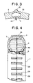
- Fig. 3 is an enlarged fragmentary circumferential cross-sectional view illustrating the tire shown in Fig. 1 with portions of the tread in their bulged position;
- Fig. 4 is a fragmentary front view, partly in radial cross-section, illustrating a second embodiment of the invention;
- Fig. 5 is an enlarged fragmentary circumferential cross-sectional view illustrating the tire shown in Fig.
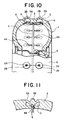
- FIG. 10 illustrates the tire of Fig. 1 having an on-off valve added thereto
- Fig. 11 illustrates the tire of Fig. 2 having an on-off valve added thereto
- Fig. 12 illustrates the tire of Fig. 3 having an on-off valve added thereto
- Fig. 13 illustrates the tire of Fig. 4 having an on-off valve added thereto
- Fig. 14 illustrates the tire of Fig.
- Fig. 15 illustrates the tire of Fig. 6 having an on-off valve added thereto
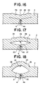
- Fig. 16 illustrates the tire of Fig. 7 having an on-off valve added thereto
- Fig. 17 illustrates the tire of Fig. 8 having an on-off valve added thereto
- Fig. 18 illustrates the tire of Fig. 9 having an on-off valve added thereto
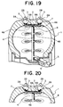
- Figs. 19 and 20 are fragmentary circumferential cross-sectional views illustrating an embodiment of the tire having the anti-skidding function according to the invention as set forth in claim 3.
- the air chambers 3 are each circular in plan, and the tread surface side wall portion 2A defining a part of each of the air chambers 3 is formed with some allowance for slack such that the tread surface side wall portion 2A is bulged out toward the tread surface and collapsed into the air chamber 3 when the air chamber 3 is inflated with air pressure and when the air chamber is evacuated of the air, respectively.
- the tread surface side wall portion 2A has a frustoconical thickened boss 2B extending from the outer surface thereof, making the rest of the wall portion 2A relatively thin-walled.
- An air supply and evacuation tube 4 is provided inside of the tread 2 centrally thereof so as to extend circumferentially on the tire and is connected through branch tubes 4A with the respective air chambers 3 disposed on opposite sides of the air supply and evacuation tube 4.
- the air supply and evacuation tube 4 is provided in its inlet/outlet port with an air valve 5.
- Figs. 10 to 12 represent a modified embodiment of the tire shown in Figs. 1 to 3 in which an on-off valve 6 is added in the connection between each of the air chambers 3 and the corresponding branch tube 4A of the air supply and evacuation tube 4.
- Figs. 10 to 12 corresponding reference numerals are used for those components which correspond to components shown in Figs. 1 to 3.
- the on-off valve 6 is opened both when the air chamber 3 is filled with air through the air supply and evacuation tube 4 and the branch tube 4A and when the air chamber 3 is evacuated of the air.
- the valve 6 is closed to seal off the air chamber 3 when the tire is used as a snow tire.
- a plurality axially elongated rectangular air chambers 3 are formed in the tread 2 in a single circumferential row at equal intervals spaced circumferentially of the tire 1. It will be seen from Figs. 4 to 6, and particularly Figs. 5 and 6 that in this embodiment the air chambers 3 are more closely spaced circumferentially of the tire 1 than in the first embodiment shown in Figs. 1 to 3.
- the tread surface side wall portion 2A defining a part of each of the air chambers 3 has a boss 2B extending from the outer surface thereof and longitudinally along the central portion thereof is formed such that the boss 2B is bulged out toward the tread surface and collapsed into the air chamber 3 when the air chamber 3 is inflated with air pressure and when the air chamber is evacuated of the air, respectively.
- Both the tread surface side wall portion 2A and the boss 2B have a relatively thin wall thickness.
- An air supply and evacuation tube 4 is provided inside of the tread 2 centrally thereof so as to extend circumferentially of the tire and is connected through branch tubes 4A with the respective air chambers 3.
- Figs. 13 to 15 represents a modified embodiment of the tire shown in Figs. 4 to 6 in which an on-off valve 6 is added in the connection between each of the air chambers 3 and the corresponding branch tube 4A of the air supply and evacuation tube 4.
- corresponding reference numerals are used for those components which correspond to components shown in Figs. 4 to 6.
- Figs. 7 to 9 show a third embodiment of the tire according to the invention in which corresponding reference numerals are used for those components which correspond to components shown in Figs. 1 to 3.
- a plurality air chambers 3 are formed in the tread 2 at equal intervals spaced circumferentially of the tire 1.
- Fig. 7 illustrates the tire in its normal tire mode of use in which the air chambers 3 are evacuated of the air.
- Fig. 8 shows the tire while the air chambers 3 are being supplied with air before being fully inflated, and
- Fig. 9 illustrates the tire in its snow tire mode of use in which the air chambers 3 are filled with air.
- Each of the air chambers 3 has a projection 2C extending from the ceiling wall thereof and a mating recess 2D formed in the floor wall thereof.
- the projection 2C is adapted to be removably snapped into the recess 2D during the normal tire mode of use.
- Figs. 16 to 18 represent a modified embodiment of the tire shown in Figs. 7 to 9 in which an on-off valve 6 is added in the connection between each of the air chambers 3 and the corresponding branch tube 4A of the air supply and evacuation tube 4.
- Figs. 16 to 18 corresponding reference numerals are used for those components which correspond to components shown in Figs. 7 to 9.
- Figs. 19 and 20 illustrates an embodiment of the invention as set forth in claim 3.
- corresponding reference numerals are used for those components which correspond to components shown in Figs. 1 to 3.
- an on-off valve in the form of a bladder 7 is provided in each of the air chambers 3 where the chambers are connected with the corresponding branch tube 4A of the air supply and evacuation tube 4.
- Fig. 19 illustrates the bladder 7 inflated with air while Fig. 20 illustrates the bladder 7 deflated or evacuated of the air.
- the bladder 7 is formed of a material such as soft rubber or synthetic resin, and is configured to assume an inverted frustoconical shape to constitute a plug for the end of the corresponding branch tube 4A of the air supply and evacuation tube 4 when the bladder 7 is inflated with air.
- the bladders 7 are evacuated of the air into their deflated state to open the associated flow paths, followed by introducing air from the air supply and evacuation tube 4 into the air chambers 3. After the air chambers 3 are filled with air, the bladders 7 are filled with air into their inflated state to plug the corresponding branch tubes 4A of the air supply and evacuation tube 4 to thereby shut off the air chambers 3 from the branch tubes 4A, sealing the air chambers.
- the bladders 7 When the tire is used in the normal tire mode of use after the snow-falling season, the bladders 7 are evacuated of the air into their deflated state to establish fluid communication between the air chambers 3 and the corresponding branch tubes 4A of the air supply and evacuation tube 4, followed by evacuating the air chambers 3 of the air through the air supply and evacuation tube 4 to thereby cause the bosses 2B to collapse into the air chambers 3.
- a valve actuating air tube 8 for controlling the operation of the bladder valves is provided inside of the tread 2 so as to extend circumferentially of the tire and is connected through branch tubes 8A with the respective bladders 7 disposed in the air chambers.
- the valve actuating air tube 8 is provided in its inlet/outlet port with an air valve 9.
- the tire according to this invention may be used as a snow tire during snow-falling winter by introducing air into the air chambers to cause the bosses on the tread to project from the tread surface. Even if the car happens to encounter a snowless road during a travel on a snow-covered road, it may continue to run while the bosses are maintained in their projected position without causing dust or noise pollutions in contrast to the conventional metal spike pins. This eliminates the need for the troublesome operation for collapsing the bosses whenever a snowless road is encountered.
- bosses are not collapsed into the air chambers even if they are subjected to pressure by contacting the ground since the on-off valve means prevents the air in the air chambers from flowing out to cause a pressure drop in the chambers. It is thus insured that the bosses perform their anti-skidding function.
- the tire may be switched to the normal tire mode of use simply by evacuating the air chambers 3 of the air to allow the bosses 2B to collapse into the air chambers 3.
- This switching operation may be easily effected, requiring only the regulation of the air pressure without the need for using any tools. It is thus to be appreciated that the present invention provides a universal tire useful throughout all seasons which may be changed between the normal tire mode of use and tire the snow mode of use.
Landscapes
- Engineering & Computer Science (AREA)
- Mechanical Engineering (AREA)
- Physics & Mathematics (AREA)
- Fluid Mechanics (AREA)
- Tires In General (AREA)
- Compositions Of Macromolecular Compounds (AREA)
Applications Claiming Priority (6)
| Application Number | Priority Date | Filing Date | Title |
|---|---|---|---|
| JP9270444A JPH1178436A (ja) | 1997-09-16 | 1997-09-16 | 滑り止め機能を有するタイヤ |
| JP270444/97 | 1997-09-16 | ||
| JP27044497 | 1997-09-16 | ||
| JP23633698 | 1998-08-06 | ||
| JP236336/98 | 1998-08-06 | ||
| JP10236336A JP2000052720A (ja) | 1998-08-06 | 1998-08-06 | 滑り止め機能を有するタイヤ |
Publications (3)
| Publication Number | Publication Date |
|---|---|
| EP0909666A2 true EP0909666A2 (de) | 1999-04-21 |
| EP0909666A3 EP0909666A3 (de) | 2000-10-18 |
| EP0909666B1 EP0909666B1 (de) | 2004-06-16 |
Family
ID=26532627
Family Applications (1)
| Application Number | Title | Priority Date | Filing Date |
|---|---|---|---|
| EP98307491A Expired - Lifetime EP0909666B1 (de) | 1997-09-16 | 1998-09-15 | Reifen mit Gleitschutzeigenschaften |
Country Status (4)
| Country | Link |
|---|---|
| US (1) | US6092576A (de) |
| EP (1) | EP0909666B1 (de) |
| AT (1) | ATE269229T1 (de) |
| DE (1) | DE69824512D1 (de) |
Cited By (2)
| Publication number | Priority date | Publication date | Assignee | Title |
|---|---|---|---|---|
| WO2001094132A1 (de) * | 2000-06-09 | 2001-12-13 | Dragan Dukic | Reifenprofil für einen luftreifen |
| EP3354482A1 (de) * | 2017-01-31 | 2018-08-01 | Robert Bosch GmbH | Verfahren und vorrichtung zur einstellung eines reifenprofils |
Families Citing this family (9)
| Publication number | Priority date | Publication date | Assignee | Title |
|---|---|---|---|---|
| US5810451A (en) * | 1996-10-17 | 1998-09-22 | O'brien; John Michael | Traction device for vehicle wheels |
| US20050092411A1 (en) * | 2003-10-31 | 2005-05-05 | O'brien John M. | Tire having expandable tread portion |
| US20080047645A1 (en) * | 2006-08-24 | 2008-02-28 | Jon Stuart Gerhardt | tractive tire method and apparatus |
| DE102010045119A1 (de) * | 2010-09-13 | 2012-03-15 | Rehau Ag + Co. | Reifen mit variablem Rollwiderstand, Vorrichtung und Verfahren zur Variation des Rollwiderstands eines Reifens |
| US9290057B2 (en) * | 2011-10-31 | 2016-03-22 | Innovative Technologies, Llc | All season safety tire |
| US9278584B2 (en) * | 2011-10-31 | 2016-03-08 | Innovative Technologies, Llc | All-weather tire |
| US20130153082A1 (en) * | 2011-12-14 | 2013-06-20 | International Business Machines Corporation | Variable friction tires |
| EP3556577B1 (de) | 2012-08-20 | 2021-03-17 | Ice Adaptive Tires, LLC | Eisadaptives reifensystem |
| US20210268838A1 (en) * | 2020-02-28 | 2021-09-02 | The Goodyear Tire & Rubber Company | Non-pneumatic tire |
Family Cites Families (17)
| Publication number | Priority date | Publication date | Assignee | Title |
|---|---|---|---|---|
| US2491491A (en) * | 1947-03-26 | 1949-12-20 | Kidde Mfg Co Inc | Pneumatic tire and antiskid means therefor |
| US2708470A (en) * | 1952-02-20 | 1955-05-17 | Clarence U Gramelspacher | Tire construction |
| US2835302A (en) * | 1955-12-30 | 1958-05-20 | Gedge Thomas James | Adjustable pneumatic tire |
| US2841199A (en) * | 1956-08-28 | 1958-07-01 | Hans J Voelkel | Traction increasing assembly for vehicle tires |
| US3712358A (en) * | 1970-09-08 | 1973-01-23 | E Einarsson | Pneumatic anti-skid vehicle tire |
| US3766956A (en) * | 1971-09-13 | 1973-10-23 | G Ruane | Tire structure |
| US3942572A (en) * | 1974-01-15 | 1976-03-09 | Crandall Azel L | Multicelled, tubeless safety tire with air activated snow and ice studs |
| US4676289A (en) * | 1984-08-13 | 1987-06-30 | Cherng Yi Su | Automobile tire having retractable tread studs |
| JPS6368408A (ja) * | 1986-09-09 | 1988-03-28 | Kiyohiro Hirakawa | 滑り止めタイヤ装置 |
| JPS63145109A (ja) * | 1986-12-05 | 1988-06-17 | Mitsuya Ooba | 可変式スパイク・スノ−タイヤ |
| JPS63215406A (ja) * | 1987-03-02 | 1988-09-07 | Minoru Sasagaki | 無公害スパイクタイヤ |
| JPH03114904A (ja) * | 1989-06-08 | 1991-05-16 | Takatoshi Suzuki | 伸縮自在スタッド付自動車用タイヤ |
| US5411070A (en) * | 1990-04-05 | 1995-05-02 | Yadegar; Iraj | Self-contained anti-skid device for pneumatic tires |
| DE9109411U1 (de) * | 1991-07-30 | 1991-10-10 | Auge, Inge, 4800 Bielefeld | Reifen für Kraftfahrzeuge |
| JPH0632111U (ja) * | 1992-10-07 | 1994-04-26 | 藤一 竹林 | タイヤの構造 |
| US5810451A (en) * | 1996-10-17 | 1998-09-22 | O'brien; John Michael | Traction device for vehicle wheels |
| BE1011592A3 (nl) * | 1997-12-09 | 1999-11-09 | Budts Ivan Hubert Constant Irm | Voertuigband. |
-
1998
- 1998-09-15 AT AT98307491T patent/ATE269229T1/de not_active IP Right Cessation
- 1998-09-15 US US09/153,376 patent/US6092576A/en not_active Expired - Fee Related
- 1998-09-15 EP EP98307491A patent/EP0909666B1/de not_active Expired - Lifetime
- 1998-09-15 DE DE69824512T patent/DE69824512D1/de not_active Expired - Lifetime
Cited By (2)
| Publication number | Priority date | Publication date | Assignee | Title |
|---|---|---|---|---|
| WO2001094132A1 (de) * | 2000-06-09 | 2001-12-13 | Dragan Dukic | Reifenprofil für einen luftreifen |
| EP3354482A1 (de) * | 2017-01-31 | 2018-08-01 | Robert Bosch GmbH | Verfahren und vorrichtung zur einstellung eines reifenprofils |
Also Published As
| Publication number | Publication date |
|---|---|
| EP0909666B1 (de) | 2004-06-16 |
| US6092576A (en) | 2000-07-25 |
| ATE269229T1 (de) | 2004-07-15 |
| EP0909666A3 (de) | 2000-10-18 |
| DE69824512D1 (de) | 2004-07-22 |
Similar Documents
| Publication | Publication Date | Title |
|---|---|---|
| US6092576A (en) | Tire having anti-slip properties | |
| US2698042A (en) | Air-sealing tire liner | |
| US2708470A (en) | Tire construction | |
| US3480064A (en) | Dual chamber tire and inflating means | |
| US3872908A (en) | Retractable studded tire | |
| US3712358A (en) | Pneumatic anti-skid vehicle tire | |
| CN1874903A (zh) | 具有可膨胀胎面部分的轮胎 | |
| US2491491A (en) | Pneumatic tire and antiskid means therefor | |
| BR102017020443A2 (pt) | Pneumático para tarefa pesada | |
| AU677169B2 (en) | Tubeless tyre beads and methods for manufacturing same | |
| US2672908A (en) | Nonskid motor vehicle tire | |
| CN107053974A (zh) | 基于阀杆的空气维持轮胎和方法 | |
| US2650632A (en) | Adjustable tire | |
| US5398742A (en) | Tire structure | |
| US4598749A (en) | Vehicle tire with traction means | |
| JP4180373B2 (ja) | タイヤおよびシーリングピースで形成された組立体およびその製造方法 | |
| US2888056A (en) | Anti-skid tire | |
| US3107713A (en) | Pneumatic tires and replaceable treads therefor | |
| US2370972A (en) | Apparatus for retreading tires | |
| US6290810B1 (en) | Mold for curing precured treads to tire casings | |
| WO2001070519A1 (en) | Pneumatic tire | |
| JP2019526490A (ja) | タイヤ表面にスタッドを配置するための手段を備えたタイヤ、および方法 | |
| US3004575A (en) | Supplemental pneumatic tire | |
| JP2018103979A (ja) | エアメンテナンスタイヤ用制御弁 | |
| JP2000052720A (ja) | 滑り止め機能を有するタイヤ |
Legal Events
| Date | Code | Title | Description |
|---|---|---|---|
| PUAI | Public reference made under article 153(3) epc to a published international application that has entered the european phase |
Free format text: ORIGINAL CODE: 0009012 |
|
| AK | Designated contracting states |
Kind code of ref document: A2 Designated state(s): AT CH DE FR GB IT LI SE |
|
| AX | Request for extension of the european patent |
Free format text: AL;LT;LV;MK;RO;SI |
|
| PUAL | Search report despatched |
Free format text: ORIGINAL CODE: 0009013 |
|
| AK | Designated contracting states |
Kind code of ref document: A3 Designated state(s): AT BE CH CY DE DK ES FI FR GB GR IE IT LI LU MC NL PT SE |
|
| AX | Request for extension of the european patent |
Free format text: AL;LT;LV;MK;RO;SI |
|
| 17P | Request for examination filed |
Effective date: 20010410 |
|
| AKX | Designation fees paid |
Free format text: AT CH DE FR GB IT LI SE |
|
| 17Q | First examination report despatched |
Effective date: 20030219 |
|
| GRAP | Despatch of communication of intention to grant a patent |
Free format text: ORIGINAL CODE: EPIDOSNIGR1 |
|
| GRAS | Grant fee paid |
Free format text: ORIGINAL CODE: EPIDOSNIGR3 |
|
| GRAA | (expected) grant |
Free format text: ORIGINAL CODE: 0009210 |
|
| AK | Designated contracting states |
Kind code of ref document: B1 Designated state(s): AT CH DE FR GB IT LI SE |
|
| PG25 | Lapsed in a contracting state [announced via postgrant information from national office to epo] |
Ref country code: LI Free format text: LAPSE BECAUSE OF FAILURE TO SUBMIT A TRANSLATION OF THE DESCRIPTION OR TO PAY THE FEE WITHIN THE PRESCRIBED TIME-LIMIT Effective date: 20040616 Ref country code: IT Free format text: LAPSE BECAUSE OF FAILURE TO SUBMIT A TRANSLATION OF THE DESCRIPTION OR TO PAY THE FEE WITHIN THE PRESCRIBED TIME-LIMIT;WARNING: LAPSES OF ITALIAN PATENTS WITH EFFECTIVE DATE BEFORE 2007 MAY HAVE OCCURRED AT ANY TIME BEFORE 2007. THE CORRECT EFFECTIVE DATE MAY BE DIFFERENT FROM THE ONE RECORDED. Effective date: 20040616 Ref country code: FR Free format text: LAPSE BECAUSE OF NON-PAYMENT OF DUE FEES Effective date: 20040616 Ref country code: CH Free format text: LAPSE BECAUSE OF FAILURE TO SUBMIT A TRANSLATION OF THE DESCRIPTION OR TO PAY THE FEE WITHIN THE PRESCRIBED TIME-LIMIT Effective date: 20040616 Ref country code: AT Free format text: LAPSE BECAUSE OF FAILURE TO SUBMIT A TRANSLATION OF THE DESCRIPTION OR TO PAY THE FEE WITHIN THE PRESCRIBED TIME-LIMIT Effective date: 20040616 |
|
| REG | Reference to a national code |
Ref country code: GB Ref legal event code: FG4D |
|
| REG | Reference to a national code |
Ref country code: CH Ref legal event code: EP |
|
| REF | Corresponds to: |
Ref document number: 69824512 Country of ref document: DE Date of ref document: 20040722 Kind code of ref document: P |
|
| PG25 | Lapsed in a contracting state [announced via postgrant information from national office to epo] |
Ref country code: SE Free format text: LAPSE BECAUSE OF FAILURE TO SUBMIT A TRANSLATION OF THE DESCRIPTION OR TO PAY THE FEE WITHIN THE PRESCRIBED TIME-LIMIT Effective date: 20040916 |
|
| PG25 | Lapsed in a contracting state [announced via postgrant information from national office to epo] |
Ref country code: DE Free format text: LAPSE BECAUSE OF FAILURE TO SUBMIT A TRANSLATION OF THE DESCRIPTION OR TO PAY THE FEE WITHIN THE PRESCRIBED TIME-LIMIT Effective date: 20040917 |
|
| REG | Reference to a national code |
Ref country code: CH Ref legal event code: PL |
|
| PLBE | No opposition filed within time limit |
Free format text: ORIGINAL CODE: 0009261 |
|
| STAA | Information on the status of an ep patent application or granted ep patent |
Free format text: STATUS: NO OPPOSITION FILED WITHIN TIME LIMIT |
|
| 26N | No opposition filed |
Effective date: 20050317 |
|
| EN | Fr: translation not filed | ||
| PGFP | Annual fee paid to national office [announced via postgrant information from national office to epo] |
Ref country code: GB Payment date: 20060915 Year of fee payment: 9 |
|
| GBPC | Gb: european patent ceased through non-payment of renewal fee |
Effective date: 20070915 |
|
| PG25 | Lapsed in a contracting state [announced via postgrant information from national office to epo] |
Ref country code: GB Free format text: LAPSE BECAUSE OF NON-PAYMENT OF DUE FEES Effective date: 20070915 |