EP0909521B1 - Communications webs for pstn subscribers - Google Patents
Communications webs for pstn subscribers Download PDFInfo
- Publication number
- EP0909521B1 EP0909521B1 EP98908903A EP98908903A EP0909521B1 EP 0909521 B1 EP0909521 B1 EP 0909521B1 EP 98908903 A EP98908903 A EP 98908903A EP 98908903 A EP98908903 A EP 98908903A EP 0909521 B1 EP0909521 B1 EP 0909521B1
- Authority
- EP
- European Patent Office
- Prior art keywords
- subscriber
- signals
- network
- digital
- wireless access
- Prior art date
- Legal status (The legal status is an assumption and is not a legal conclusion. Google has not performed a legal analysis and makes no representation as to the accuracy of the status listed.)
- Expired - Lifetime
Links
Images


Classifications
-
- H—ELECTRICITY
- H04—ELECTRIC COMMUNICATION TECHNIQUE
- H04W—WIRELESS COMMUNICATION NETWORKS
- H04W84/00—Network topologies
- H04W84/02—Hierarchically pre-organised networks, e.g. paging networks, cellular networks, WLAN [Wireless Local Area Network] or WLL [Wireless Local Loop]
- H04W84/10—Small scale networks; Flat hierarchical networks
- H04W84/16—WPBX [Wireless Private Branch Exchange]
-
- H—ELECTRICITY
- H04—ELECTRIC COMMUNICATION TECHNIQUE
- H04M—TELEPHONIC COMMUNICATION
- H04M1/00—Substation equipment, e.g. for use by subscribers
- H04M1/71—Substation extension arrangements
- H04M1/715—Substation extension arrangements using two or more extensions per line
-
- H—ELECTRICITY
- H04—ELECTRIC COMMUNICATION TECHNIQUE
- H04M—TELEPHONIC COMMUNICATION
- H04M1/00—Substation equipment, e.g. for use by subscribers
- H04M1/72—Mobile telephones; Cordless telephones, i.e. devices for establishing wireless links to base stations without route selection
- H04M1/725—Cordless telephones
- H04M1/72502—Cordless telephones with one base station connected to a single line
- H04M1/72505—Radio link set-up procedures
-
- H—ELECTRICITY
- H04—ELECTRIC COMMUNICATION TECHNIQUE
- H04M—TELEPHONIC COMMUNICATION
- H04M1/00—Substation equipment, e.g. for use by subscribers
- H04M1/253—Telephone sets using digital voice transmission
- H04M1/2535—Telephone sets using digital voice transmission adapted for voice communication over an Internet Protocol [IP] network
Definitions
- PSTN public switched telephone network
- Twisted pair is a small pipe.
- Standards such as ADSL aim to break through these physically-imposed limitations by delivering multiple channels on a single line and splitting analog and digital channels at the customer demarcation point in a manner that allows digital signals to be delivered to a nearby computer.
- Standards have also evolved, such as 100-base-T, to squeeze performance from the installed twisted pair plant, but limits dictated by the non-shielded nature of that medium will always exist.
- any physical wiring plant or medium, present or future will suffer electrical and thus transport limitations due to wireline, coaxial, fiber or other medium physical properties and characteristics. Connectivity in the residence which avoids such physically-imposed pipe constrictions would therefore be beneficial.
- subscribers will require an ever increasing array of computers and other connected electronic devices throughout the residence.
- Such devices will include not only those which resemble computers or televisions in nature which require a large data pipe to support graphics, video and audio content. They may also be any electronic device one wishes to access remotely, many of which will tax the infrastructure in their own way with, for instance, new consumer electronics standards and interactive requirements.
- the anticipated 128 bit Internet protocol address format can, it is estimated, support every lightbulb in the world, each with its own IP address.
- Residential connectivity must accordingly take into account not only the magnitude and nature of additional capacity demand imposed by each new device, but also the increasing volume of the new devices with which subscribers will inevitably populate their residences and small businesses.
- a subscriber wireless telephone subsystem for coupling subscriber telephony equipment to a Public Switched Telephone Network (PSTN) as defined above and wherein the network control unit is networked to the PSTN or another telecommunications infrastructure signaling and control network and the programmable switching means includes an interface unit adapted to be remotely programmed either for subscriber control or control by a service bureau.
- PSTN Public Switched Telephone Network
- At least one of the network interface units is analog or digital and or hybrid and at least a respective one of the wireless access units is analog or digital or hybrid.
- one item of subscriber telephony equipment is a handset comprising interface circuitry to receive downstream signals from the multiplex/demultiplex circuitry to analog and render the downstream signals compatible for use by the handset for at least a loudspeaker in the handset, and to receive upstream signals from a microphone in the handset, convert said upstream signals to digital and render the signals compatible for use by and delivery to the multiplex/demultiplex circuitry.
- the interface unit is programmed from an external source comprising a service bureau; or it is coupled to be programmed by a personal computer or a button or keyboard interface.
- the or each network control unit and the or each wireless access unit or the or each network control unit and the or each handset are adapted to control the level of power radiated by the transceiver circuitry in order to reduce interference between adjacent networks: or it or they are .
- control processors of network control units of different subscribers are coupled and adapted to co-ordinate with one another to control the network transceiver units frequency use and radiated power level in order to minimize mutual interference.
- the network transceiver units are adapted to monitor radio-frequency transmissions radiated by other subsystems s and control its frequency use and radiated power level accordingly.
- the network control unit is adapted to be connected to four public switched telecommunication network (PSTN) lines and comprises four analog interfaces, each interface comprising its own analog/digital conversion circuitry or sharing a common analog/digital conversion circuitry.
- PSTN public switched telecommunication network
- the switch is adapted to be controlled to couple communications among at least two of the group comprising the wireless access units of subscriber equipment, and incoming lines to the network control unit.
- a process for connecting a plurality of lines of a switched telecommunications infrastructure in a communications web to subscriber equipment comprises the steps of:-
- At least one of the line signals is analog or digital or hybrid and at least a respective one of the wireless access units is analog or digital or hybrid.
- analog line signals are digitized and coupled to the programmable switch from wireless access unit and analog subscriber equipment signals are digitized and coupled to the wireless access unit.
- programming the switch is conducted remotely of the communications web via the telecommunications infrastructure or another signaling and control network; or it is conducted by a personal computer or a button or keyboard interface coupled to the switch.
- radio-frequency transmissions from other communications webs are detected and the power and frequency of radio-frequency transmissions in the communications web is adjusted according to the other radio-frequency transmissions.
- Systems according to the present invention feature a Network Control Unit or Web Control Unit ("NCU") which interfaces to any desired number of PSTN connections. Where the connections are analog, a Network Interface in the NCU digitizes the signals and otherwise renders them compatible for delivery to a crossconnect switch, which may be internal.
- the switch may be programmed in the connect switch, which may be internal.
- the switch may be programmed in the residence or remotely to connect signals from each PSTN connection via radiofrequency link efficiently and in a frequency spectrum-conservative manner to any number and combination of wireless jacks or wireless access units. These wireless access units accompany and connect to the subscriber's telephones, computers, fax machines, and other electronic devices in the residence or small business.
- Subscribers can, therefore, configure their communications webs to accommodate their own communications needs by programming the switch based on the number and nature of their PSTN connections, their present and future telephones, computers, fax machines and other devices, and their personal preferences about, for instance, what lines should ring and be connected where in the residence.
- Handsets and/or Wireless Access Units or wireless jacks employed in communications webs of the present invention may comprise relatively simple and inexpensive electronics to receive and process the radiofrequency link based signals and connect them to the subscriber equipment.
- the handsets include a transceiver, multiplex / demultiplex circuits, analog / digital conversion circuits such as so-called "codec's" and control circuitry with a combination of, for instance, microphone and earphone for voice communications, and perhaps a jack for data communications.
- Wireless Access Units contain circuitry similar to the handset in analog environments, plus additional circuitry for delivery of the signal to a standard interface such as an RJ-11 jack.
- Such Wireless Access Units can be made available, according to the present invention, to accommodate any physical and electrical interface standard, such as Wireless Access Units for ISDN interfaces and any other desired digital services.
- the subscriber can simply buy a new, relatively inexpensive digital Wireless Access Unit with RS 232 port, connect that unit to the computer, reprogram the Network Control Unit to connect the new ISDN connection and new Wireless Access Unit, and thereby be connected via an efficient RF link rather than needing to call a contractor to tear the walls out.
- the PSTN connections may therefore terminate in the residence at a Network Control Unit which may be physically small and innocuous in appearance, perhaps placed on a table or counter or mounted on a wall and, if desired, coupled to a nearby electrical outlet and to a controller such as a personal computer or other interface if the user desires control other than by interfaces on the Network Control Unit itself.
- the unit may feature a stub antenna, enclosed planar antenna or other desired antenna.
- any device desired to connect to the PSTN can connect to or contain its own Wireless Access Unit which may be battery powered and connect to the NCU via the RF link. No additional physical medium need be planted.
- the present invention accordingly makes possible wireless, efficient, flexible and modular connectivity between any desired device and the PSTN (or other telecommunications infrastructure) within the residence or small business.
- the Network Control Unit itself may be modular in design to accommodate various circuit boards for various changing and evolving standards and protocols. Multiple NCU's may be employed, or multiple NCU functionality may be incorporated into a unit, in order to accommodate objectives such as, for instance, diversity, hand-off capability and additional capacity.
- New Wireless Access Units may be purchased for whatever particular devices a particular subscriber desires, and he or she may update the system with new circuit boards and new Wireless Access Units and perhaps new handsets as time passes, new devices and services evolve, and standards change.
- the Network Control Unit may be programmed by the subscriber using an interface on the unit. It may be connected via network or PSTN link to a remote programming source, either for the subscriber's control or control by a service bureau. Such programming of the Network Control Unit, and other control and signaling, may occur via connectivity to the PSTN signaling and control infrastructure, including the so-called "Advanced Intelligence Networks.”
- Figure 1 is a schematic view of a residence which features one embodiment of a system according to the present invention.
- FIG. 2 is a schematic, greatly simplified, representation of a Time Division Multiplex Access (“TDMA”) frame having eight slots supporting four bi-directional channels in accordance with one embodiment of the present invention.
- TDMA Time Division Multiplex Access
- Figure 3A is a high level functional block diagram of a Network Control Unit according to one embodiment of the present invention.
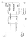
- Figure 3B is a schematic diagram, at a lower level than Figure 3A, of a Network Control Unit according to one embodiment of the present invention in which four coder / decoder or "codec's" are employed in connection with four analog POTS lines.
- Figure 3C is a functional block diagram of a single code which may accommodate the four lines, for instance, shown in Figure 3B as an alternative design for purely analog POTS lines.
- Figure 4 is a functional block diagram of one embodiment of a handset according to the present invention.
- FIG. 5 is a functional block diagram of one embodiment of a Wireless Access Unit according to the present invention.
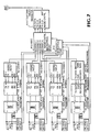
- Figure 6 is a functional block diagram of a Network Control Unit which is adapted to accommodate the ISDN standard, alone or in connection with other analog PSTN connections.
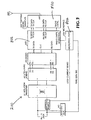
- Figure 7 is a functional block diagram of a Network Control Unit according to the present invention adapted to accommodate three analog and one digital PSTN connections.
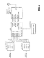
- Figure 8 is a functional block diagram of one embodiment of a digital Wireless Access Unit according to the present invention.
- Figures 9A and 9B are functional block diagrams as one embodiment of switching / processing circuitry contained in one embodiment of a Wireless Access Unit or handset according to the present invention.
- Figure 10 is a high level functional block diagram of transceiver circuitry which may be employed in the present invention if desired.
- Figure 11A is a simplified flow diagram illustrating one configuration sequence of the Network Control Unit of Figure 3.
- Figure 11B is a table showing configuration of the Network Control Unit of Figure 3 resulting from the configuration sequence shown in Figure 11A.
- Figure 12 is a schematic diagram showing operation of a communications web according to the present invention according to Example 1 discussed below.
- Figure 13 is a schematic diagram showing operation of another communications web according to the present invention according to Example 2 discussed below.
- FIG. 1 is a schematic hypothetical floor plan for a residence or business containing one simple embodiment of a communications web according to the present invention.
- the floor plan shows a Network Control Unit or "NCU" 100 which terminates four central office POTS lines or connections designated “CO1" through “CO4."
- the connections may occur other than in the so-called “local loop.” They may also occur in any medium, including wireline, coaxial, fiber, terrestrial radiofrequency link, satellite link.
- Each connection may supply any number and sort of communications channels, including analog or digital according to any present or future standard, format or protocol.
- the connections may also originate in or contain signals transported by telecommunications infrastructure or networks other than the PSTN, whether switched or non-switched, circuit based switched, packet based switched or otherwise.
- PSTN Public Switchetelecommunications network
- a number of Wireless Access Units or wireless jacks (“WAU's") 201 - 203 may be found throughout the floor plan, linked via RF link to the NCU. Additionally, a number of handsets and conventional telephones 300 - 304 whether portable or connected to a WAU may also be found throughout the floor plan. Other electronic devices such as a fax 400 may be included; fax 400 in Figure 1 is shown connected to a WAU 202.
- WAU's according to the present invention which may be RF linked to one or more NCUs for a particular location, can be adapted to accommodate any telecommunication, consumer electronic or other required standard, format or protocol, whether analog or digital and can be manufactured and sold individually for that purpose to render communications webs according to the present invention modular in nature with a mix of components to suit every reasonable taste and preference.
- a WAU may connect to, for instance, a "telephone", such as telephone instrument 300 in Figure 1, a conventional modem, directly to a personal computer via ISDN WAU, to a fax machine via fax WAU, or any other desired electronic device.
- FIG. 1 is simply a hypothetical floor plan in order to provide a modicum of topological perspective relative to NCUs, WAUs, handsets and other electronic devices as employed in communications webs of the present invention.
- FIGS 3A through 3C show, in functional block diagram format, embodiments and portions of embodiments of Network Control Units ("NCU's") according to the present invention.
- NCU 100 includes interface circuitry for interfacing with PSTN or other lines or connections from a switch or other component of the PSTN or other telecommunications transport infrastructure or network, whether analog or digital.
- This circuitry denominated "Network Interface” 650 as shown in Figure 3A, couples to switching (and, if desired, bridging and accessory) circuitry as shown with numeral 660 in Figure 3A.
- This discussion considers signals in a "downstream" or a PSTN to NCU to WAU direction, from which corresponding signal flow in the opposite direction is apparent.
- the Cross Connect Switch / Conference Bridge / Accessory Block (“CAB”) components couple signals from the Network Interface corresponding to incoming lines, in a predetermined and programmable manner, with additional functionality, if desired, to downstream circuitry for eventual RF transmission to WAU's and handsets.
- the switching and bridging components of the CAB are the portion of the Network Control Unit that allow the subscriber either remotely or locally to designate by programming into the NCU which of his or her telephone instruments, computers, fax machines, and other devices connect to various PSTN lines at particular times of day or under particular conditions. Either or both of the Bridging and Accessory circuits may be omitted, if desired, so that the CAB only performs the switching functionality.
- the signals being properly switched in the CAB as designated for the subscriber's devices are then delivered to the NCU's "Radio Multiplex Engine” as shown in Figure 3A with numeral 670.
- the RME multiplexes the signals as, for instance, by time division multiplex access, or according to any desired format, onto a number of predetermined channels for bandwidth and RF frequency conservation.
- the multiplexed signals are delivered to Radio Transceiver 680 where the signals may be conditioned, again multiplexed according to any desired format, and modulated onto an appropriate RF carrier or carriers in a programmable manner or as otherwise desired for transmission to WAUs 200, handsets 300 and other devices if desired.
- Multiplexing, modulation, and other processing in order to render signals at the CAB output compatible for RF transmission may occur in the same module or any desired combination of modules or circuits.
- An NCU Controller 690 connects to all circuits in the NCU and may be programmed via user interface on the NCU, via computer coupled to the Controller or other portions of the NCU, or remotely over one of the incoming lines 640.
- the Controller 690 may itself be networked to the PSTN or other telecommunications infrastructure signaling and control network, such as for remote or partially remote control by Advanced Intelligence Networks or other signaling and control networks.
- the Network Interface 650 of the NCU may be modular in design and contains the circuits that connect to the public switched telephone network for accommodating various media, including twisted pair, coax, fiber and wireless, and various modes, including analog, digital or a hybrid.
- a Network Interface may be modular and portions for all lines may be implemented in applications specific integrated circuitry ("ASIC") medium to accommodate analog circuits, or services requiring, among other interfaces, ISDN, T-1, CATV/COAX, ATM, micro-ATM, AMPS, N-AMPS, TDMA digital cellular, CDMA digital cellular, analog or digital SMR (Nextel), PCS, LEO satellite, geosychronous satellite, Internet protocol or any other present or future form of wireless or wireline local loop or other telecommunications infrastructure service.
- ASIC applications specific integrated circuitry
- the Network Interface for a system according to the present invention which accommodates four POTS lines, could take the form of a quad arrangement of independent Direct Access Arrangement ("DAA") circuits 690, each having appropriate transformer, isolator and line protection circuitry as required, a two to four wire hybrid 700, and a coder / decoder ("code") 10.
- the Network Interface circuitry is accordingly adapted for appropriate isolation, impedance matching, line protection, medium conversion (two wire to four wire) and analog-to-digital / digital-to-analog conversion in order for its output signal 720 to be coupled to CAB 660.
- the functionality in POTS versions of direct access arrangement circuits 690 comprises conventional components and is conventionally implemented.
- Figure 3C shows an alternative arrangement for a Network Interface adapted to accommodate four POTS lines.
- the line conditioning circuitry which can include hybrids 700 and other components cross-couples to a single code 710, instead of the requirement that a code be employed for each line 640.
- Output of the Network Interface may be on a bus 730 instead of individual outputs coupled to CAB 660, in order to couple Network Interface 650 to CAB 660 via a multiplexed connection for physical simplicity and logical implementation.
- the Network Interface may be the so-called "U-Interface" and associated 4-level dibit modem circuitry.
- Other digital services require a Network Interface especially adapted to interface to a particular medium, format and protocol.
- the Network Interface may be a wireless modem which includes a radio receiver or transceivers and appropriate modulation / demodulation, coding and decoding circuitry.
- the Network Interface is a wireless modem / Radio Transceiver
- the NCU 100 operates as a radio transponder or rebroadcast unit, communicating with the PSTN via one wireless protocol, and with the WAUs 200, handsets 300 and other components of systems according to the present invention via the same or perhaps different protocols.
- This aspect of the invention may be counterintuitive: If the connection to the PSTN is wireless, one approach is simply to connect directly to any location in the residence instead of relaying signals through the NCU 100.
- a handset 300 or a WAU 200 according to the present invention is a far simpler and less expensive device which need only accommodate the present invention's less stringent internal air interface standards, but nevertheless retain the functionality to provide corded quality and reliability for indoor / nearby outdoor service that is inexpensive, compact, lightweight, flexible and manufactured and sold, if desired, tailored to specific devices such as faxes or various digital standards which not every subscriber may wish to employ.
- Incoming connections to the Network Interface 650 could be physically separate twisted pairs as in the case of analog POTS lines where each line terminates from the PSTN via an independent twisted pair; alternatively, each incoming circuit can be multiplexed over a single pair, such as two digital circuits provided by a conventional, basic rate (2B + D) ISDN line.
- a 6 megabit per second micro-ATM fiber connection could provide digital voice service, MPEG-2 digital video and other services over a single optical fiber which could be de-multiplexed (multiplexed for outgoing or upstream information) in the Network Interface, and incoming lines could be virtual. That is, additional lines could be assigned on an as needed basis and charged accordingly. For example, a subscriber might have connection to one line from 10:00 p.m.
- the CAB 660 can be programmed to accommodate changes in the PSTN connections in real time in order to distribute bandwidth and service as desired among various WAUs 200, handsets 300 and the other end user interface devices.
- the NCU 100 may be capable of routing calls or sessions via the global information infrastructure, whether or not compressed (such as, for instance, using elemedia branded compression or other compression). Such an NCU 100 adapted for this purpose at present may employ NetPhone branded functionality, as one example of presently available suitable functionality. Successors will be equally suitable.
- Cross connect switch / conference bridge / accessory blocks may be, electronically or virtually, an n x m switch which is programmed to interconnect any incoming signal 720 from the Network Interface 650, (whether physical, virtual, multiplexed or wireless) to a number of output signals or interfaces which correspond to communications channels, according to one topology, or to combinations of the handsets, telephones, fax machines, computers or other devices serviced by WAU's 200 and/or handsets 300 of the present invention, according to another topology.
- the CAB 660 can, but need not, include functionality simply to bridge or conference these same circuits and/or remote devices, thus eliminating the need for further processing of the signals beyond CAB 660.
- a CAB may additionally contain a variety of decoders, generators, synthesizers and other circuits as desired.
- CAB 660 is preferably coupled to a local Control Processor and/or an external computer and/or network or server, if desired.
- the external connection may be directly by bus or synchronous connection, or via any of the PSTN lines 640.
- CABs 660, Control Processors 690 and other components may be coupled and/or networked among various NCUs and/or external / or server control capacity.
- the CAB shown in Figure 3A is under control of a local Control Processor 685 and personal computer 687.
- the CAB 660 may function similar to a central switchboard and conference bridge routing each line to one or more Wireless Access Units 200 and/or handsets 300 as programmed in Control Processors 685 and/or PC 687.
- Multiple lines 640, handsets 300, telephones connected to WAUs 200, and other devices may be conferenced to form any number of permutations and combinations of conferences.
- One wireless handset can call another without using any of external lines 640 simply using the allotted time slots, codes or RF channels involving the two handsets 300, or telephones connected to a WAU 200.
- a conference call of any two or more internal handset or telephone devices can similarly occur. Calls or conferences among multiple devices on multiple networked or shared NCU's can similarly occur.
- the CAB 660 can be implemented in analog circuits including relays, transistors, CMOS media or any other application specific or nonspecific analog components and/or integrated circuits, but preferably signals 720 arriving at CAB 660 are digital so that CAB 660 may be implemented entirely digitally.
- CABs 660 are adapted to route and direct data signals, such as, for example, when using external data services via Internet or internal networks within the subscriber's location.
- virtual circuits may be established for each call which can remain in place for the duration of a call.
- CSMA Carrier Since Multiple Access
- ATM Asynchronous Transfer Mode
- packet switching protocol can be employed, among other formats or protocols, in order to support a larger number of bursty devices.
- a combination of virtual data circuits and CSMA can be employed if desired.
- CABs 660 are also adapted to accommodate voice and data traffic simultaneously, routing traffic and managing resources as desired.
- Conference Bridge functionality in the CAB 660 is preferably implemented as a high quality digital bridge which maintains all connections at suitable and equal audio levels.
- the Conference Bridge functionality can be implemented in analog circuits, again it is preferably implemented digitally using logic or digital signal processing. Digital leveling and noise control may be used to maintain voice circuit quality regardless of the numbers of parties bridged together.
- the Conference Bridge may also be adapted to bridge in one or more outside lines onto an existing circuit, adding handsets 300 and/or WAUs 200 to the circuit.
- the Accessory Block functionality may contain features which add flexibility and additional levels of services to communications webs according to the present invention.
- the Accessory Block functionality may include, for instance, DTMF generator, DTMF decoder, speech synthesizer, speech recognizer, speech compression expander (ADCPM), digital speech interpolation (DSI), caller ID decoder, low or high speed telephone modem, fax modem capable of Group III or similar functions, real time clock / calendar digital telephone answering device (TAD) and other functionality as desired.
- Control Processor 685 and other portions of CAB 660 to implement capability such as autodialing, remote programmability, voice command features, digital voice prompting, voice store and forward, and other advanced functionality.
- Portions or all of the Accessory Block Functionality may be sited on board or remote to NCU 100 as desired for particular implementations. External connections can adapt the NCU to an existing external fax / modem unit, for instance.
- Functionality which may also be included in the NCU 100 includes intelligent call control.
- a CPT generator included in NCU 100 can generate simulated dial tone when off hook.
- the NCU 100 interprets touch-tone dialing inputs from a handset 300 or WAU 200, adds appropriate prefix or other signaling, or for instance, automatically adds new and changed area code signaling for dialing a number which the NCU 100 recognizes but whose area code or other call control information has changed.
- the NCU 100 can correct dialing errors in single digits of familiar numbers in order to prevent misdials and wrong numbers.
- Such functionality can be employed to add signaling so that the user need only dial a portion of the number, similar to automatic "fastfill" data entry in conventional software applications.
- Such signaling can also reflect intelligence within the device or based at least in part on information to which the NCU 100 connects, which provides least cost routing to different long distance carriers according to time, and station called, among other factors.
- Various other signaling capabilities can be implemented and automated as desired, including those such as automating the Internet Service Provider / Long Distance server.
- the NCU Switching, Bridging and Accessory Block functionality or any other software employed by NCU 100 may reside on board the NCU and may but need not be remotely programmable or upgradeable. It may also incorporate remotely accessed or pushed program and or data objects and/or applications as desired, including in the JAVA, Active/X, or other languages. It may also include any other desired application, including, for instance, voice / data encryption among the NCU 100, WAU 200 and handset 300 for privacy, network security, fraud protection and authentication.
- NCU's 100 preferably include a standard connector such as an RJ-11 connector which may be hardwired to a single line telephone or connected, for example, to existing in-home wiring.
- This connector permits the NCU 100 to manage the existing telephone or wiring as part of its network, perhaps permitting them to answer any ringing line.
- a POTS NCU 100 could have a drop out relay or FET circuit which may automatically switch the existing wiring over to this connector in the event of a power failure or a system failure. If the NCU 100 is equipped with backup batteries or other auxiliary power, it may continue to function either until mains power is restored or its batteries become exhausted in which case it drops off-line and switches to the emergency bypass routing to the external connector.
- Control Processor 685 commands switching, routing, RF, accessory and other functionality implemented in CAB 660, Radio Transceiver 680 and other circuits in NCU 100s according to the present invention.
- Control Processor 685 could be a small micro-controller chip, although more processing power may be required to accommodate ISDN and other digital interface NCUs 100.
- external PCS 687 and, if desired, servers may participate in the control functions.
- a very simple algorithm by which the Control Processor 685 governs CAB 660 for the topology shown in Figure 1 is shown in Figures 11A and 11B, in which, step-by-step, lines 640 are matched in the CAB 660 to various WAUs 200, handsets 300, and other devices.
- the control algorithms and programming itself may occur locally as by an interface 689 which may be implemented in buttons or a keyboard, by PC 687 or external connection, including network or telecommunications infrastructure.
- systems of the present invention are adapted to permit control of the NCU 100, including Control Processor 685 and CAB 660 from a remote service center so that a subscriber can call the service center in the event the subscriber feels technically short of the task of programming his or her NCU to accommodate various WAUs 200 and handsets 300.
- Configuration data could also be downloaded from a website.
- PC and other external connectivity leverages on higher intelligence of the PC, additional mass memory functionality for updates and databases and similar applications, the more convenient user interface, and more elaborate applications software such as, for instance, directory management, spreadsheets and database managers, PC based speech synthesis and recognition software.
- CAB output signals 750 are coupled to a radio multiplex engine 670 according to the present invention which can comprise a digital logic block that implements any of the following functionality: multiplexing / demultiplexing, preferably but not necessarily TDMA / TDD (Time Division Multiplex Access / Time Division Duplex), forward error control and general error management, speech compression if required, code division multiplex and demultiplexing, if any, hopset generation if any, and other critical timing, synchronization and coding functions critical to the operation of the systems according to the present invention.
- TDMA / TDD Time Division Multiplex Access / Time Division Duplex
- forward error control and general error management speech compression if required
- code division multiplex and demultiplexing if any, hopset generation if any, and other critical timing, synchronization and coding functions critical to the operation of the systems according to the present invention.
- RME's 670 generally but not necessarily operate at speeds sufficiently high to render Control Processor 685 management ineffective, although that need not be the case.
- RME signals 770 are coupled, in systems of the present invention, to wireless Radio Transceiver ("RT") circuitry 680 as shown in Figure 3A.
- the RT 680 may be a low cost multiplexed Radio Transceiver or set of transceivers which provides proper modulation onto RF carriers as desired with or without multiplexing and duplexing according to any of the following formats or others: TDMA / TDD, TDMA / FDD, CDMA / FDD, CDMA / TDD, FDMA / TDD, or FDMA / FDD, or any of these with frequency hopping or direct frequency spread spectrum.
- the primary function is to achieve transmission of multiple simultaneous independent data streams to WAUs 200 and handsets 300.
- Multiplexing is but one aspect of the larger issue of bandwidth conservation and resource sharing, which also includes duplexing and channelizing, among other things.
- multiplexing means methods of multiple remote units communicating simultaneously with a common NCU 100 for access to the PSTN.
- Duplexing means methods of simultaneous upstream and downstream communications, such as simultaneous communications from an NCU 100 to a given handset 300 and from the handset back to the NCU.
- Channelizing means methods of bandwidth sharing so that multiple systems, each consisting of an NCU, handsets and WAU's, which may happen to fall within radio range of one another, such as in an apartment building, for instance, can share the same band but not interfere with one another.
- Time division multiplexing and code division multiplexing are both acceptable forms of multiplexing, among others, for purposes of the present invention.
- carrier bandwidth is narrower than code division multiplexing access bandwidth, facilitating frequency-domain channelizing.
- CDMA could also be employed for channelizing, such as, for instance, the different NCU's using orthogonal spreading codes on the same RF carrier frequency, it is generally necessary to control transmit power levels very tightly so that the well-known near-far problem of direct sequency spread spectrum does not create difficulty. This means that it would be necessary to coordinate the transmit power levels from one NCU to the next and among the handsets as well. This could be a technically challenging problem.
- CDMA cellular and PCS systems that are in place as of this disclosure use frequency division duplexing (FDD) rather than time division duplexing (TDD) for bi-directional communications. It would not be practical to use CDMA for duplexing at present. Using TDD, it is possible to use the same RF channel for bi-directional communications. TDD also eliminates the need for the costly duplex filter that routes transmit energy to the antenna away from the receiver and vice versa, replacing it with a relatively compact, inexpensive duplex switch. TDMA/TDD with frequency-domain channelizing is therefore the preferred embodiment of duplexing as of this disclosure. Time division multiplexing is preferred over FDMA, at present, because FDMA would require the generation of a separate carrier for each of four or more independent communications links, which is expensive.
- FDD frequency division duplexing
- TDD time division duplexing
- DMT/TDD may offer some advantages in multipath fading environments over TDD, and may be considered. This option is economically imposing until DMT (also known as orthogonal discrete frequency modulation or ODFM), which requires rapid fast Fourier transform and inverse FFT calculations, becomes more tractable using conventional DSP engines.
- DMT also known as orthogonal discrete frequency modulation or ODFM
- ODFM orthogonal discrete frequency modulation
- the RT circuitry 680 need not conform to any error interface standard, since it communicates only with like equipment and usually does not interface to the PSTN or any other public network except via a separate, higher quality transceiver if any is implemented in the Network Interface 650 or connected to it.
- Systems according to the invention can be implemented with any number of modulation formats. Those include partial response, quadrature partial response (QPR), binary phase shift keying (BPSK), differential binary phase shift keying (DBPSK), quadrature phase shift keying (QPSK), differential quadrature phase shift keying (DQPSK), pi-over-four quadrature phase shift keying (pi/4QPSK), pi-over-four differential quadrature phase shift keying (pi/4DQPSK), frequency shift keying (FSK), four- or eight- level FM, discrete multitone (DMT) (or orthogonal discrete frequency modulation).
- QPR quadrature partial response
- BPSK binary phase shift keying
- DBPSK differential binary phase shift keying
- QPSK quadrature phase shift keying
- DQPSK differential quadrature phase shift keying
- pi/4QPSK differential quadrature phase shift keying
- pi/4DQPSK pi-over-four quadrature phase shift keying
- Any modulation format can be overlaid with spread spectrum.
- Frequency hopping can be used as a multiple access technique.
- Spread spectrum systems are afforded the advantage of higher transmit power under the radio rules governing unlicensed radio transmitters in some countries, including the U.S. and Canada.
- some direct sequence implementations have anti-multipath properties which can be exploited to provide more robust communications. Both techniques may offer some advantages with respect to mitigating interference from like or unlike systems operating within the same bandwidth. For these reasons, spread spectrum techniques may be employed in the preferred embodiment of the invention.
- the RT unit 680 can communicate with other NCUs 100 that fall within radio range.
- the NCUs 100 can share hopset data interference records, timing and usage information, all toward the end of avoiding one another's transmissions.
- the components of each system, NCUs 100, WAUs 200, handsets 300 all transmit at the lowest power necessary to provide reliable communications, using power management sensing and response to interference or other criteria. In this manner, each system minimizes its "radius of interference," the approximate circular area surrounding a given system within which it is capable of generating interference in other (like or unlike) systems operating in the same band.
- Wireless Access Units 200 may be of two general sorts: (1) analog for a wireless telephone jack function such as one that can accommodate a telephone or a conventional modem; or (2) digital, for a wireless computer or digital device connection (such as DB-25, USB, Ethernet, ISDN-ST, PCMCIA or similar serial or parallel data communications connection).
- analog for a wireless telephone jack function such as one that can accommodate a telephone or a conventional modem
- digital, for a wireless computer or digital device connection such as DB-25, USB, Ethernet, ISDN-ST, PCMCIA or similar serial or parallel data communications connection.
- FIG. 5 shows one form of analog WAU 200 according to the present invention.
- the analog WAU 200 may include a Radio Transceiver 800 which links WAU 200 via RF connection to NCU 100, a Radio Multiplex Engine 802, a Control Processor 804, and circuitry that provides basic subscriber loop functions of battery, over voltage protection, ringing, supervision (off hook sensing), code, hybrid and test functionality (so called borscht) functionality.
- the analog WAU 200 of Figure 5 may be implemented in a small unit which resembles a wall transformer with one or more RJ-11 jacks on the back or side, and it can, if desired, draw power from any AC outlet and provide an analog telephone type connection to a computer modem, a fax machine, a telephone answering device, a standard telephone or any other device that connects with a standard RJ-11 jack.
- the unit may but need not be transparent to caller ID information, passing it through from the PSTN. Similarly, the unit may pass through coded ringing and other custom signaling.
- Its power supply provides power for standard telephones which are line powered. Its high voltage ring generator rings telephones with the standard 90 volt rms., 20-Hz ring signal or other standards for foreign countries.
- this unit is typically though not necessarily “wired” to the AC power wiring and therefore is not totally “wireless,” the link between this unit and the incoming lines 640 connected to NCU 100 is wireless. It therefore eliminates the subscriber's need to place telephones where telephone outlets are located. Battery power, if employed, allows totally wireless operation, providing even more flexibility in location.
- a digital Wireless Access Unit 200 of one sort according to the present invention is shown in Figure 6.
- Such a Wireless Access Unit 200 can provide wireless connection to computers, computer peripherals, ISDN-ST telephone sets and other digital devices. Since the radio link used in systems according to the present invention is digital, the digital circuitry in the Wireless Access Unit 200 principally performs a buffering, error control, and protocol conversion function.
- the external digital interface can take many forms, including DB-25, the standard serial port connector; USB, Intel's new universal serial bus standard; parallel-port (printer) connection; Ethernet; 10-base-T; 100-base-T, Fast or Gigabit Ethernet; PCMCIA and others.
- the WAU 200 may be of the sort which is adapted to operate with an external fax / modem such as shown, for instance, in Fig. 13.
- Digital Wireless Access Unit 200 like analog Wireless Access Unit 200, may be mains or battery powered, so that they may provide untethered convenience to the user.
- Systems according to the present invention can also perform many control and monitoring functions at a subscriber's location for convenience and increased efficiency.
- a wireless doorbell accessory or WAU 200 can emit a coded ring in response to a ringing doorbell signal. The subscriber could then press an "intercom" soft key, placing the subscriber in full duplex communications with the front door visitor and possibly calling up his or her image on a display.
- Other wireless accessories can provide control over home lighting, garage door opening, and security monitoring.
- the handset or other interface device can control televisions, stereo equipment, heating, air conditioning and appliances. Baby monitoring via wireless audio monitor and other consumer electronics functionality are accommodated by the present system, whether or not via the CE-bus.
- the four main component parts of systems of the present invention are the Network Control Unit 100, Wireless Access Units 200, handsets 300 and Wireless Control / Monitoring Accessories 350. While each component may contain an onboard microcontroller which governs its basic functions, the NCU 100 alone or acting in concert with external controller capacity is preferably the principal controller and manager of the entire communications web. All remote components are preferably simple, reliable and preferably of limited intelligence / functionality for reduced costs and increased modularity and so that system performance and functions are principally determined by the NCU 100.
- the NCU 100 may contain on-line firmware and/or software upgrade capability as discussed above.
- the NCU 100 is the central part of the systems' star network topology. for the entire system, the NCU 100 selects RF channels, hop sequences if any, and spreading codes if any; it managers ID strings for the various remotes, and it performs the other functions related to network management, remote unit registration and authentication, and communications protocol management.
- the NCU 100 also controls the switching and interconnection of the CAB 660, and drives all the Accessory Block features of CAB 660.
- the following examples describe operation of two embodiments of the communications webs according to the present invention.
- a system according to the present invention is shown in Figure 12 with four incoming POTS lines, an NCU 100 in the basement or attic, a wireless handset; and three Wireless Access Units 200 which correspond to a telephone, a computer, and a fax machine.
- the system may be programmed as follows: POTS line 1 is programmed in the CAB 660 to ring through and connect to the LCD handset 300. POTS line 2 rings through and connects to Wireless Access Unit number 1 which is connected to a standard telephone via an RJ-11 jack. POTS line 3 connects to Wireless Access Unit number 2, which, in turn, accommodates a fax machine. POTS line 4 connects to Wireless Access Unit number 3 which connects via RS-232 interface to a personal computer.
- Signals from POTS lines 1-4 are coupled to Radio Multiplex Engine 670, multiplexed as in TDMA format and modulated onto an RF carrier in RT or digital radio modem 680 for transmission.
- Handset 300 receives the signal from the NCU 100, and demodulates, demultiplexes and processes the information intended for handset 300. That information is contained in a signal provided to the interfacing circuitry and coder / decoder 650 for delivery to the human interface. The signals are also provided to an LCD driver and screen. In an upstream direction, signals from the keypad and microphone are processed, multiplexed, modulated and forwarded to NCU 100 which ultimately demodulates, demultiplexes and processes the signals for delivery to POTS line 1.
- Wireless Access Units 1-3 operate generally in a similar manner as far as the RF and multiplexing circuitry are concerned.
- Wireless Access Unit number 1 contains interface circuitry adapted to accommodate a standard telephone, including, for example, coder / decoder circuitry, line interface, battery, supervision, and ring generator circuitry which interfaces to an RF-11 jack.
- Wireless Access Unit number 2 interface circuitry intended for a fax machine may be similar or identical to Wireless Access Unit number 1.
- Wireless Access Unit number 3 is configured with interface circuitry to accommodate a RS-232 port rather than an RF-11 analog jack. Accordingly, forward error correction, universal asynchronous receiver / transmitter and handshaking circuitry is included in connection with RS-232 serial port standards.
- POTS line 3 could be reprogrammed in the CAB 660 to accommodate Wireless Access Unit number 3 for computer communications while POTS line 2 is configured to ring through to Wireless Access Units 1 and 2 for the telephone and fax machine. Any other combination may be employed as desired, as the user desires new services or different services, or adds devices to the communications web with their attendant Wireless Access Units.
- POTS line 1 is programmed in CAB 660 of Network Control Unit 100 to ring through and connect to LCD handset 300.
- POTS line 2 is programmed to ring through and connect to Wireless Access Units number 1 and number 2, which in turn connect to the standard telephone and a fax machine, respectively.
- the ISDN line is programmed to connect to Wireless Access Unit number 3 and thus to a computer via a serial port Again, the lines may be programmed to connect to various handsets 300 and Wireless Access Units 200 as needed as the user desires new or additional services or adds other devices. With the existing devices shown in Fig.
- the user could program CAB 660 to connect POTS line 1 to handset 300 and Wireless Access Units 1 and 2 in order to eliminate the second POTS line.
- line 1 could be designated the voice line for connection to handset 300 and Wireless Access Unit number 1.
- Line 1 or Line 2 could also be wired in the Network Interface 650 or otherwise to connect directly through to existing wiring as shown in Figure 13.
Abstract
Description
- Demand for access to voice and data communications on the public switched telephone network ("PSTN") is growing exponentially. Not only is the subscriber base expanding logarithmically, but even more significantly, individual subscribers are beginning to require more than one connection and frequently multiple connections. In addition to cellular telephones, pagers, and other mobile devices, residence-based connectivity is a significant factor in this exponential growth of the PSTN. Subscribers have begun in recent times and in significant volume to require second and third connections as a matter of course, such as for Global Information Infrastructure (so-called "Internet") connectivity, facsimile and data communications and for children's' lines.
- Although it is conventional for a residence to contain standard telephone devices in various rooms supported by one line and perhaps a computer supported by another, the days of standard analog "plain old telephone service" or "POTS" are being overshadowed by the demand for connections with sufficient capacity to support graphics, video, interactive applications and devices, and the so-called "push technology." In 1995, for instance, the Regional Bell Operating Companies ("RBOC's") began transporting more data than voice communications. Accordingly, not only are subscribers employing more lines; the nature of the connection is also changing. The rate of change will only increase over time.
- The increased demand for residential subscriber connections, and the ever changing nature of those connections as new standards emerge for new and different services, confront a serious physical obstacle: the permanent physically limited nature of the residential wiring plant. Twisted pair is a small pipe. Standards such as ADSL aim to break through these physically-imposed limitations by delivering multiple channels on a single line and splitting analog and digital channels at the customer demarcation point in a manner that allows digital signals to be delivered to a nearby computer. Standards have also evolved, such as 100-base-T, to squeeze performance from the installed twisted pair plant, but limits dictated by the non-shielded nature of that medium will always exist. In any event, any physical wiring plant or medium, present or future, will suffer electrical and thus transport limitations due to wireline, coaxial, fiber or other medium physical properties and characteristics. Connectivity in the residence which avoids such physically-imposed pipe constrictions would therefore be beneficial.
- Inevitably, subscribers will require an ever increasing array of computers and other connected electronic devices throughout the residence. Such devices will include not only those which resemble computers or televisions in nature which require a large data pipe to support graphics, video and audio content. They may also be any electronic device one wishes to access remotely, many of which will tax the infrastructure in their own way with, for instance, new consumer electronics standards and interactive requirements. For example, the anticipated 128 bit Internet protocol address format can, it is estimated, support every lightbulb in the world, each with its own IP address. Residential connectivity must accordingly take into account not only the magnitude and nature of additional capacity demand imposed by each new device, but also the increasing volume of the new devices with which subscribers will inevitably populate their residences and small businesses.
- Presently, most residences feature only twisted pair wiring in the walls. Even at the time of this writing, that plant is often insufficient for the requirements imposed by certain conventional residence based computer equipment. Rewiring for additional lines throughout the house, whether via today's twisted pair or perhaps coax standard, is trouble and expense enough, as well as a great disincentive which constricts demand for increased residential bandwidth. As time passes and the rate of technology change increases, however, subscribers could find themselves needing to rewire every several years in order to accommodate changing standards and the need for an ever greater distribution pipe. Although fiber plants could theoretically provide a solution; cost considerations rule them out as a practical solution for most residences and small businesses.
- These factors create a need for connectivity in the residence between the PSTN customer demarcation point and an ever increasing array and volume of telephones, fax machines, bandwidth-intensive devices such as computers and televisions, and any other device which may be connected to the PSTN or feature an IP address. Such connectivity must suffice not only for today; it must alleviate the need to rewire the residence in order to accommodate new changes. It must accommodate new devices, formats, protocols and standards, whether analog or digital. It must be flexible and modular in design in order to accommodate a wide-ranging, ever changing, ever evolving set of needs and preferences among the subscriber base. It cannot afford to be constricted by the physically imposed limitations inherent in wireline, coaxial, fiber, or other physical residential plants. Yet it must be a reasonably priced solution in order to avoid imposing a constriction on growth and evolution of the telecommunications distribution infrastructure.
- Document US - A - 5 555 258 discloses a subscriber wireless telephone subsystem for coupling subscriber telephony equipment to a Public Switched Telephone Network (PSTN) comprising:-
- a) a network control unit adapted to be coupled to at least one PSTN line, the
network control unit including:-
- i) network interface units for transforming signals received from the or each PSTN line into first digital signals and for transforming other received digital signals into signals for coupling to the PSTN line or lines,
- ii) network transceiver units coupled to the network interface units for
transmitting the first digital signals and for receiving and coupling the other received
digital signals to the network interface units, the network transceiver units being
multiple channel, radio-frequency transceiver means arranged to respond to the first
digital signals by placing selected portions thereof into selected portions of a
multiplex frame,
and, - iii) programmable switching means provided for associating the or selected PSTN
lines and selected portions of the multiplex frame for connecting to subscriber
telephony equipment,
and, - b) at least one wireless access unit comprising :-
- i) remote transforming units for transforming signals received from the
subscriber telephony equipment into second digital signals and transform other
received digital signals into signals for the subscriber telephony equipment,
and, - ii) remote transceiver units being multiple channel, radio-frequency transceiver means arranged to respond to and place the second digital signals into selected portions of the multiplex frame and coupled to the remote transforming means for transmitting the second digital signals and for receiving and coupling other received digital signals to the remote interface units,
- c) the programmable switching means being adapted to be programmed with instructions from the subscriber to configure the network control unit so as to associate or dedicate at least one the subscriber telephony equipment to the or at least one of the PSTN lines and for any one of the subscriber telephony equipment to use the multiplex frame to communicate to any other one of the subscriber telephony equipment.
-
- According to the present invention a subscriber wireless telephone subsystem for coupling subscriber telephony equipment to a Public Switched Telephone Network (PSTN) as defined above and wherein the network control unit is networked to the PSTN or another telecommunications infrastructure signaling and control network and the programmable switching means includes an interface unit adapted to be remotely programmed either for subscriber control or control by a service bureau.
- According to a first embodiment of the present invention, at least one of the network interface units is analog or digital and or hybrid and at least a respective one of the wireless access units is analog or digital or hybrid.
- According to a second embodiment of the present invention, one item of subscriber telephony equipment is a handset comprising interface circuitry to receive downstream signals from the multiplex/demultiplex circuitry to analog and render the downstream signals compatible for use by the handset for at least a loudspeaker in the handset, and to receive upstream signals from a microphone in the handset, convert said upstream signals to digital and render the signals compatible for use by and delivery to the multiplex/demultiplex circuitry.
- According to a third embodiment of the present invention, the interface unit is programmed from an external source comprising a service bureau; or it is coupled to be programmed by a personal computer or a button or keyboard interface.
- According to a fourth embodiment of the present invention, the or each network control unit and the or each wireless access unit or the or each network control unit and the or each handset are adapted to control the level of power radiated by the transceiver circuitry in order to reduce interference between adjacent networks: or it or they are .
- According to a fifth embodiment of the present invention, the control processors of network control units of different subscribers are coupled and adapted to co-ordinate with one another to control the network transceiver units frequency use and radiated power level in order to minimize mutual interference.
- According to a sixth embodiment of the present invention, the network transceiver units are adapted to monitor radio-frequency transmissions radiated by other subsystems s and control its frequency use and radiated power level accordingly.
- According to a seventh embodiment of the present invention, the network control unit is adapted to be connected to four public switched telecommunication network (PSTN) lines and comprises four analog interfaces, each interface comprising its own analog/digital conversion circuitry or sharing a common analog/digital conversion circuitry.
- According to an eighth embodiment of the present invention,
- a. at least some of a plurality of network analog interfaces are adapted to:-
- convert analog signals to digital in the downstream direction,
- render the signals compatible with circuitry in the network control unit,
- convert digital signals to analog in the upstream direction for delivery to subscriber
telephony equipment,
and, - render the upstream signals compatible with the subscriber telephony equipment;
and, - b. at least one analog wireless access unit comprises interface circuitry adapted
to:-
- receive downstream signals from the multiplex/demultiplex circuitry,
- convert the downstream signals to analog,
- render the downstream signals compatible for use by subscriber telephony equipment for delivery to at least one interface to the subscriber telephony equipment,
- receive upstream signals from the subscriber telephony equipment from the or one of the interfaces,
- convert the upstream signals to digital,
and, - render the upstream signals compatible for use by and delivery to the multiplex/demultiplex circuitry.
-
- According to a ninth embodiment of the present invention, the switch is adapted to be controlled to couple communications among at least two of the group comprising the wireless access units of subscriber equipment, and incoming lines to the network control unit.
- Also according to the present invention, a process for connecting a plurality of lines of a switched telecommunications infrastructure in a communications web to subscriber equipment comprises the steps of:-
- a. coupling line signals to at least one output of a programmable switch;
- b. multiplexing the coupled signals;
- c. modulating the multiplexed line signals into at least one radio-frequency line signal;
- d. transmitting the radio-frequency line signal to a plurality of wireless access units;
- e. in each wireless access unit:-
- i. receiving the transmitted line signal,
- ii. demodulating and demultiplexing the received line signal,
- iii. identifying portions of the demultiplexed line signal intended for that wireless access unit, the identified portions corresponding to line signals programmed in the switch to be connected to subscriber equipment connected to that wireless access unit;
- iv. multiplexing and modulating signals from subscriber equipment into a
radio-frequency subscriber signal,
and - v. transmitting the radio-frequency subscriber signals;
- f. receiving the radio-frequency subscriber signals from the wireless access units;
- g. demodulating and demultiplexing the radio-frequency subscriber signals;
- h. programming the switching means with instructions from the subscriber to configure the network control unit so as to associate or dedicate at least one the subscriber telephony equipment to the or at least one of the PSTN lines and for any one of the subscriber telephony equipment to use the multiplex frame to communicate to any other one of the subscriber telephony equipment and,
- i. and networking the network control unit to the PSTN or another telecommunications infrastructure signaling and control network and programming an interface unit included in the programmable switching means either for subscriber control or control by a service bureau.
-
- According to a first embodiment of the process according to the present invention, at least one of the line signals is analog or digital or hybrid and at least a respective one of the wireless access units is analog or digital or hybrid.
- According to a second embodiment of the process according to the present invention, analog line signals are digitized and coupled to the programmable switch from wireless access unit and analog subscriber equipment signals are digitized and coupled to the wireless access unit.
- According to a third embodiment of the process according to the present invention, programming the switch is conducted remotely of the communications web via the telecommunications infrastructure or another signaling and control network; or it is conducted by a personal computer or a button or keyboard interface coupled to the switch.
- According to a fourth embodiment of the process according to the present invention, radio-frequency transmissions from other communications webs are detected and the power and frequency of radio-frequency transmissions in the communications web is adjusted according to the other radio-frequency transmissions.
- Systems according to the present invention feature a Network Control Unit or Web Control Unit ("NCU") which interfaces to any desired number of PSTN connections. Where the connections are analog, a Network Interface in the NCU digitizes the signals and otherwise renders them compatible for delivery to a crossconnect switch, which may be internal. The switch may be programmed in the connect switch, which may be internal. The switch may be programmed in the residence or remotely to connect signals from each PSTN connection via radiofrequency link efficiently and in a frequency spectrum-conservative manner to any number and combination of wireless jacks or wireless access units. These wireless access units accompany and connect to the subscriber's telephones, computers, fax machines, and other electronic devices in the residence or small business. Subscribers can, therefore, configure their communications webs to accommodate their own communications needs by programming the switch based on the number and nature of their PSTN connections, their present and future telephones, computers, fax machines and other devices, and their personal preferences about, for instance, what lines should ring and be connected where in the residence.
- Handsets and/or Wireless Access Units or wireless jacks employed in communications webs of the present invention may comprise relatively simple and inexpensive electronics to receive and process the radiofrequency link based signals and connect them to the subscriber equipment. The handsets include a transceiver, multiplex / demultiplex circuits, analog / digital conversion circuits such as so-called "codec's" and control circuitry with a combination of, for instance, microphone and earphone for voice communications, and perhaps a jack for data communications.
- Wireless Access Units contain circuitry similar to the handset in analog environments, plus additional circuitry for delivery of the signal to a standard interface such as an RJ-11 jack. Such Wireless Access Units can be made available, according to the present invention, to accommodate any physical and electrical interface standard, such as Wireless Access Units for ISDN interfaces and any other desired digital services. When a subscriber decides to connect a new computer to the PSTN via an ISDN line, for example, the subscriber can simply buy a new, relatively inexpensive digital Wireless Access Unit with
RS 232 port, connect that unit to the computer, reprogram the Network Control Unit to connect the new ISDN connection and new Wireless Access Unit, and thereby be connected via an efficient RF link rather than needing to call a contractor to tear the walls out. - The PSTN connections may therefore terminate in the residence at a Network Control Unit which may be physically small and innocuous in appearance, perhaps placed on a table or counter or mounted on a wall and, if desired, coupled to a nearby electrical outlet and to a controller such as a personal computer or other interface if the user desires control other than by interfaces on the Network Control Unit itself. The unit may feature a stub antenna, enclosed planar antenna or other desired antenna. Throughout the residence, any device desired to connect to the PSTN can connect to or contain its own Wireless Access Unit which may be battery powered and connect to the NCU via the RF link. No additional physical medium need be planted.
- The present invention accordingly makes possible wireless, efficient, flexible and modular connectivity between any desired device and the PSTN (or other telecommunications infrastructure) within the residence or small business. The Network Control Unit itself may be modular in design to accommodate various circuit boards for various changing and evolving standards and protocols. Multiple NCU's may be employed, or multiple NCU functionality may be incorporated into a unit, in order to accommodate objectives such as, for instance, diversity, hand-off capability and additional capacity. New Wireless Access Units may be purchased for whatever particular devices a particular subscriber desires, and he or she may update the system with new circuit boards and new Wireless Access Units and perhaps new handsets as time passes, new devices and services evolve, and standards change.
- The Network Control Unit may be programmed by the subscriber using an interface on the unit. It may be connected via network or PSTN link to a remote programming source, either for the subscriber's control or control by a service bureau. Such programming of the Network Control Unit, and other control and signaling, may occur via connectivity to the PSTN signaling and control infrastructure, including the so-called "Advanced Intelligence Networks."
- It is accordingly a feature of the present invention to provide a flexible, modular system which provides connectivity between the PSTN or other telecommunications infrastructure and any desired electronic devices a subscriber wishes to connect, via RF link.
- It is an additional feature of the present invention to provide business and residential wireless connectivity between the PSTN and computers, handsets, and other devices which eliminates the need to rewire businesses and residences in order to accommodate new standards and services.
- It is an additional feature of the present invention to provide RF-based connectivity between any number of PSTN lines and any number of now existing or future electronic devices, in a modular and flexible manner.
- Other features and advantages of the present invention will become apparent with respect to the remainder of this document.
- Figure 1 is a schematic view of a residence which features one embodiment of a system according to the present invention.
- Figure 2 is a schematic, greatly simplified, representation of a Time Division Multiplex Access ("TDMA") frame having eight slots supporting four bi-directional channels in accordance with one embodiment of the present invention.
- Figure 3A is a high level functional block diagram of a Network Control Unit according to one embodiment of the present invention.
- Figure 3B is a schematic diagram, at a lower level than Figure 3A, of a Network Control Unit according to one embodiment of the present invention in which four coder / decoder or "codec's" are employed in connection with four analog POTS lines.
- Figure 3C is a functional block diagram of a single code which may accommodate the four lines, for instance, shown in Figure 3B as an alternative design for purely analog POTS lines.
- Figure 4 is a functional block diagram of one embodiment of a handset according to the present invention.
- Figure 5 is a functional block diagram of one embodiment of a Wireless Access Unit according to the present invention.
- Figure 6 is a functional block diagram of a Network Control Unit which is adapted to accommodate the ISDN standard, alone or in connection with other analog PSTN connections.
- Figure 7 is a functional block diagram of a Network Control Unit according to the present invention adapted to accommodate three analog and one digital PSTN connections.
- Figure 8 is a functional block diagram of one embodiment of a digital Wireless Access Unit according to the present invention.
- Figures 9A and 9B are functional block diagrams as one embodiment of switching / processing circuitry contained in one embodiment of a Wireless Access Unit or handset according to the present invention.
- Figure 10 is a high level functional block diagram of transceiver circuitry which may be employed in the present invention if desired.
- Figure 11A is a simplified flow diagram illustrating one configuration sequence of the Network Control Unit of Figure 3.
- Figure 11B is a table showing configuration of the Network Control Unit of Figure 3 resulting from the configuration sequence shown in Figure 11A.
- Figure 12 is a schematic diagram showing operation of a communications web according to the present invention according to Example 1 discussed below.
- Figure 13 is a schematic diagram showing operation of another communications web according to the present invention according to Example 2 discussed below.
- Figure 1 is a schematic hypothetical floor plan for a residence or business containing one simple embodiment of a communications web according to the present invention. The floor plan shows a Network Control Unit or "NCU" 100 which terminates four central office POTS lines or connections designated "CO1" through "CO4." In embodiments other than the particular one shown in Figure 1, the connections may occur other than in the so-called "local loop." They may also occur in any medium, including wireline, coaxial, fiber, terrestrial radiofrequency link, satellite link. Each connection may supply any number and sort of communications channels, including analog or digital according to any present or future standard, format or protocol. The connections may also originate in or contain signals transported by telecommunications infrastructure or networks other than the PSTN, whether switched or non-switched, circuit based switched, packet based switched or otherwise. For convenience in disclosing structure and operation of communications webs according to the present invention, however, reference will be made to the PSTN, but in a non-limiting fashion.
- A number of Wireless Access Units or wireless jacks ("WAU's") 201 - 203 may be found throughout the floor plan, linked via RF link to the NCU. Additionally, a number of handsets and conventional telephones 300 - 304 whether portable or connected to a WAU may also be found throughout the floor plan. Other electronic devices such as a
fax 400 may be included; fax 400 in Figure 1 is shown connected to aWAU 202. - Any number of connections may terminate in one or more NCUs for a particular location according to the present invention. Similarly, WAU's according to the present invention, which may be RF linked to one or more NCUs for a particular location, can be adapted to accommodate any telecommunication, consumer electronic or other required standard, format or protocol, whether analog or digital and can be manufactured and sold individually for that purpose to render communications webs according to the present invention modular in nature with a mix of components to suit every reasonable taste and preference. A WAU may connect to, for instance, a "telephone", such as
telephone instrument 300 in Figure 1, a conventional modem, directly to a personal computer via ISDN WAU, to a fax machine via fax WAU, or any other desired electronic device. A number of WAUs and handsets may be employed according to the present invention to accommodate any particular combination of electronic devices the subscriber desires to have connected to the PSTN. Figure 1 is simply a hypothetical floor plan in order to provide a modicum of topological perspective relative to NCUs, WAUs, handsets and other electronic devices as employed in communications webs of the present invention. - Figures 3A through 3C show, in functional block diagram format, embodiments and portions of embodiments of Network Control Units ("NCU's") according to the present invention. According to a preferred embodiment of the present invention,
NCU 100 includes interface circuitry for interfacing with PSTN or other lines or connections from a switch or other component of the PSTN or other telecommunications transport infrastructure or network, whether analog or digital. This circuitry, denominated "Network Interface" 650 as shown in Figure 3A, couples to switching (and, if desired, bridging and accessory) circuitry as shown with numeral 660 in Figure 3A. This discussion considers signals in a "downstream" or a PSTN to NCU to WAU direction, from which corresponding signal flow in the opposite direction is apparent. - The Cross Connect Switch / Conference Bridge / Accessory Block ("CAB") components couple signals from the Network Interface corresponding to incoming lines, in a predetermined and programmable manner, with additional functionality, if desired, to downstream circuitry for eventual RF transmission to WAU's and handsets. The switching and bridging components of the CAB are the portion of the Network Control Unit that allow the subscriber either remotely or locally to designate by programming into the NCU which of his or her telephone instruments, computers, fax machines, and other devices connect to various PSTN lines at particular times of day or under particular conditions. Either or both of the Bridging and Accessory circuits may be omitted, if desired, so that the CAB only performs the switching functionality.
- The signals being properly switched in the CAB as designated for the subscriber's devices are then delivered to the NCU's "Radio Multiplex Engine" as shown in Figure 3A with
numeral 670. The RME multiplexes the signals as, for instance, by time division multiplex access, or according to any desired format, onto a number of predetermined channels for bandwidth and RF frequency conservation. The multiplexed signals are delivered toRadio Transceiver 680 where the signals may be conditioned, again multiplexed according to any desired format, and modulated onto an appropriate RF carrier or carriers in a programmable manner or as otherwise desired for transmission toWAUs 200,handsets 300 and other devices if desired. Multiplexing, modulation, and other processing in order to render signals at the CAB output compatible for RF transmission, may occur in the same module or any desired combination of modules or circuits. - An
NCU Controller 690 connects to all circuits in the NCU and may be programmed via user interface on the NCU, via computer coupled to the Controller or other portions of the NCU, or remotely over one of theincoming lines 640. TheController 690 may itself be networked to the PSTN or other telecommunications infrastructure signaling and control network, such as for remote or partially remote control by Advanced Intelligence Networks or other signaling and control networks. - In greater detail, the
Network Interface 650 of the NCU may be modular in design and contains the circuits that connect to the public switched telephone network for accommodating various media, including twisted pair, coax, fiber and wireless, and various modes, including analog, digital or a hybrid. A Network Interface may be modular and portions for all lines may be implemented in applications specific integrated circuitry ("ASIC") medium to accommodate analog circuits, or services requiring, among other interfaces, ISDN, T-1, CATV/COAX, ATM, micro-ATM, AMPS, N-AMPS, TDMA digital cellular, CDMA digital cellular, analog or digital SMR (Nextel), PCS, LEO satellite, geosychronous satellite, Internet protocol or any other present or future form of wireless or wireline local loop or other telecommunications infrastructure service. As shown in Figure 3B, the Network Interface for a system according to the present invention which accommodates four POTS lines, could take the form of a quad arrangement of independent Direct Access Arrangement ("DAA")circuits 690, each having appropriate transformer, isolator and line protection circuitry as required, a two to fourwire hybrid 700, and a coder / decoder ("code") 10. The Network Interface circuitry is accordingly adapted for appropriate isolation, impedance matching, line protection, medium conversion (two wire to four wire) and analog-to-digital / digital-to-analog conversion in order for itsoutput signal 720 to be coupled toCAB 660. (The functionality in POTS versions of directaccess arrangement circuits 690 comprises conventional components and is conventionally implemented.) - Figure 3C shows an alternative arrangement for a Network Interface adapted to accommodate four POTS lines. There, the line conditioning circuitry which can include
hybrids 700 and other components cross-couples to asingle code 710, instead of the requirement that a code be employed for eachline 640. Output of the Network Interface may be on a bus 730 instead of individual outputs coupled toCAB 660, in order to coupleNetwork Interface 650 toCAB 660 via a multiplexed connection for physical simplicity and logical implementation. For ISDN, the Network Interface may be the so-called "U-Interface" and associated 4-level dibit modem circuitry. Other digital services require a Network Interface especially adapted to interface to a particular medium, format and protocol. - For any of the wireless local loop or so called fixed wireless services including satellite, the Network Interface may be a wireless modem which includes a radio receiver or transceivers and appropriate modulation / demodulation, coding and decoding circuitry. When the Network Interface is a wireless modem / Radio Transceiver, the
NCU 100 operates as a radio transponder or rebroadcast unit, communicating with the PSTN via one wireless protocol, and with theWAUs 200,handsets 300 and other components of systems according to the present invention via the same or perhaps different protocols. This aspect of the invention may be counterintuitive: If the connection to the PSTN is wireless, one approach is simply to connect directly to any location in the residence instead of relaying signals through theNCU 100. However, systems according to the present invention address a problem this approach would present, because Radio Transceivers that interface to the PSTN typically must comply with elaborate air interface standards having precise frequency control, well-defined RF bandwidth, higher transmit power (to accommodate the greater distance to a cell tower or PCS antenna), better receiver sensitivity, higher battery drain and shorter battery life, and increase complexity and expense. Ahandset 300 or aWAU 200 according to the present invention, however, is a far simpler and less expensive device which need only accommodate the present invention's less stringent internal air interface standards, but nevertheless retain the functionality to provide corded quality and reliability for indoor / nearby outdoor service that is inexpensive, compact, lightweight, flexible and manufactured and sold, if desired, tailored to specific devices such as faxes or various digital standards which not every subscriber may wish to employ. - Incoming connections to the
Network Interface 650 could be physically separate twisted pairs as in the case of analog POTS lines where each line terminates from the PSTN via an independent twisted pair; alternatively, each incoming circuit can be multiplexed over a single pair, such as two digital circuits provided by a conventional, basic rate (2B + D) ISDN line. A 6 megabit per second micro-ATM fiber connection could provide digital voice service, MPEG-2 digital video and other services over a single optical fiber which could be de-multiplexed (multiplexed for outgoing or upstream information) in the Network Interface, and incoming lines could be virtual. That is, additional lines could be assigned on an as needed basis and charged accordingly. For example, a subscriber might have connection to one line from 10:00 p.m. to 7:00 a.m., two lines from 7:00 a.m. to 9:00 a.m. and four lines from 9:00 a.m. to 7:00 p.m. and be billed accordingly for the partial use. As discussed below, theCAB 660 can be programmed to accommodate changes in the PSTN connections in real time in order to distribute bandwidth and service as desired amongvarious WAUs 200,handsets 300 and the other end user interface devices. - The
NCU 100 may be capable of routing calls or sessions via the global information infrastructure, whether or not compressed (such as, for instance, using elemedia branded compression or other compression). Such anNCU 100 adapted for this purpose at present may employ NetPhone branded functionality, as one example of presently available suitable functionality. Successors will be equally suitable. - Cross connect switch / conference bridge / accessory blocks ("CAB's") according to the present invention may be, electronically or virtually, an n x m switch which is programmed to interconnect any
incoming signal 720 from theNetwork Interface 650, (whether physical, virtual, multiplexed or wireless) to a number of output signals or interfaces which correspond to communications channels, according to one topology, or to combinations of the handsets, telephones, fax machines, computers or other devices serviced by WAU's 200 and/orhandsets 300 of the present invention, according to another topology. TheCAB 660 can, but need not, include functionality simply to bridge or conference these same circuits and/or remote devices, thus eliminating the need for further processing of the signals beyondCAB 660. A CAB may additionally contain a variety of decoders, generators, synthesizers and other circuits as desired. -
CAB 660 is preferably coupled to a local Control Processor and/or an external computer and/or network or server, if desired. The external connection may be directly by bus or synchronous connection, or via any of the PSTN lines 640. In systems according to the present invention having multiple NCUs,CABs 660,Control Processors 690 and other components may be coupled and/or networked among various NCUs and/or external / or server control capacity. - The CAB shown in Figure 3A is under control of a
local Control Processor 685 andpersonal computer 687. For voice services, theCAB 660 may function similar to a central switchboard and conference bridge routing each line to one or moreWireless Access Units 200 and/orhandsets 300 as programmed inControl Processors 685 and/orPC 687.Multiple lines 640,handsets 300, telephones connected toWAUs 200, and other devices may be conferenced to form any number of permutations and combinations of conferences. One wireless handset can call another without using any ofexternal lines 640 simply using the allotted time slots, codes or RF channels involving the twohandsets 300, or telephones connected to aWAU 200. A conference call of any two or more internal handset or telephone devices can similarly occur. Calls or conferences among multiple devices on multiple networked or shared NCU's can similarly occur. - The
CAB 660, like other components in the NCU, the WAU's and the handsets, can be implemented in analog circuits including relays, transistors, CMOS media or any other application specific or nonspecific analog components and/or integrated circuits, but preferably signals 720 arriving atCAB 660 are digital so thatCAB 660 may be implemented entirely digitally. -
CABs 660, according to the present invention, are adapted to route and direct data signals, such as, for example, when using external data services via Internet or internal networks within the subscriber's location. In the voice case, virtual circuits may be established for each call which can remain in place for the duration of a call. In the data case, a Carrier Since Multiple Access ("CSMA"), Asynchronous Transfer Mode ("ATM") or packet switching protocol can be employed, among other formats or protocols, in order to support a larger number of bursty devices. A combination of virtual data circuits and CSMA can be employed if desired. In similar fashion,CABs 660, according to the present invention, are also adapted to accommodate voice and data traffic simultaneously, routing traffic and managing resources as desired. - Conference Bridge functionality in the
CAB 660 is preferably implemented as a high quality digital bridge which maintains all connections at suitable and equal audio levels. Although the Conference Bridge functionality can be implemented in analog circuits, again it is preferably implemented digitally using logic or digital signal processing. Digital leveling and noise control may be used to maintain voice circuit quality regardless of the numbers of parties bridged together. The Conference Bridge may also be adapted to bridge in one or more outside lines onto an existing circuit, addinghandsets 300 and/orWAUs 200 to the circuit. - The Accessory Block functionality, which may, but need not, form a portion of
CABs 660 according to the present invention, may contain features which add flexibility and additional levels of services to communications webs according to the present invention. The Accessory Block functionality may include, for instance, DTMF generator, DTMF decoder, speech synthesizer, speech recognizer, speech compression expander (ADCPM), digital speech interpolation (DSI), caller ID decoder, low or high speed telephone modem, fax modem capable of Group III or similar functions, real time clock / calendar digital telephone answering device (TAD) and other functionality as desired. These functions are provided in conjunction with theControl Processor 685 and other portions ofCAB 660 to implement capability such as autodialing, remote programmability, voice command features, digital voice prompting, voice store and forward, and other advanced functionality. Portions or all of the Accessory Block Functionality may be sited on board or remote toNCU 100 as desired for particular implementations. External connections can adapt the NCU to an existing external fax / modem unit, for instance. - Functionality which may also be included in the
NCU 100 includes intelligent call control. For instance, a CPT generator included inNCU 100 can generate simulated dial tone when off hook. TheNCU 100 interprets touch-tone dialing inputs from ahandset 300 orWAU 200, adds appropriate prefix or other signaling, or for instance, automatically adds new and changed area code signaling for dialing a number which theNCU 100 recognizes but whose area code or other call control information has changed. Likewise, theNCU 100 can correct dialing errors in single digits of familiar numbers in order to prevent misdials and wrong numbers. Such functionality can be employed to add signaling so that the user need only dial a portion of the number, similar to automatic "fastfill" data entry in conventional software applications. Such signaling can also reflect intelligence within the device or based at least in part on information to which theNCU 100 connects, which provides least cost routing to different long distance carriers according to time, and station called, among other factors. Various other signaling capabilities can be implemented and automated as desired, including those such as automating the Internet Service Provider / Long Distance server. - The NCU Switching, Bridging and Accessory Block functionality or any other software employed by
NCU 100 may reside on board the NCU and may but need not be remotely programmable or upgradeable. It may also incorporate remotely accessed or pushed program and or data objects and/or applications as desired, including in the JAVA, Active/X, or other languages. It may also include any other desired application, including, for instance, voice / data encryption among theNCU 100,WAU 200 andhandset 300 for privacy, network security, fraud protection and authentication. - NCU's 100 according to the present invention preferably include a standard connector such as an RJ-11 connector which may be hardwired to a single line telephone or connected, for example, to existing in-home wiring. This connector permits the
NCU 100 to manage the existing telephone or wiring as part of its network, perhaps permitting them to answer any ringing line. Alternatively, aPOTS NCU 100 could have a drop out relay or FET circuit which may automatically switch the existing wiring over to this connector in the event of a power failure or a system failure. If theNCU 100 is equipped with backup batteries or other auxiliary power, it may continue to function either until mains power is restored or its batteries become exhausted in which case it drops off-line and switches to the emergency bypass routing to the external connector. -
Control Processor 685 according to the present invention commands switching, routing, RF, accessory and other functionality implemented inCAB 660,Radio Transceiver 680 and other circuits in NCU 100s according to the present invention.Control Processor 685 could be a small micro-controller chip, although more processing power may be required to accommodate ISDN and otherdigital interface NCUs 100. Then,external PCS 687 and, if desired, servers, may participate in the control functions. A very simple algorithm by which theControl Processor 685 governsCAB 660 for the topology shown in Figure 1 is shown in Figures 11A and 11B, in which, step-by-step,lines 640 are matched in theCAB 660 tovarious WAUs 200,handsets 300, and other devices. The control algorithms and programming itself may occur locally as by aninterface 689 which may be implemented in buttons or a keyboard, byPC 687 or external connection, including network or telecommunications infrastructure. - Alternatively, systems of the present invention are adapted to permit control of the
NCU 100, includingControl Processor 685 andCAB 660 from a remote service center so that a subscriber can call the service center in the event the subscriber feels technically short of the task of programming his or her NCU to accommodate various WAUs 200 andhandsets 300. Configuration data could also be downloaded from a website. - PC and other external connectivity leverages on higher intelligence of the PC, additional mass memory functionality for updates and databases and similar applications, the more convenient user interface, and more elaborate applications software such as, for instance, directory management, spreadsheets and database managers, PC based speech synthesis and recognition software.
- CAB output signals 750 are coupled to a
radio multiplex engine 670 according to the present invention which can comprise a digital logic block that implements any of the following functionality: multiplexing / demultiplexing, preferably but not necessarily TDMA / TDD (Time Division Multiplex Access / Time Division Duplex), forward error control and general error management, speech compression if required, code division multiplex and demultiplexing, if any, hopset generation if any, and other critical timing, synchronization and coding functions critical to the operation of the systems according to the present invention. - RME's 670 according to the present invention generally but not necessarily operate at speeds sufficiently high to render
Control Processor 685 management ineffective, although that need not be the case. - RME signals 770 are coupled, in systems of the present invention, to wireless Radio Transceiver ("RT")
circuitry 680 as shown in Figure 3A. TheRT 680 may be a low cost multiplexed Radio Transceiver or set of transceivers which provides proper modulation onto RF carriers as desired with or without multiplexing and duplexing according to any of the following formats or others: TDMA / TDD, TDMA / FDD, CDMA / FDD, CDMA / TDD, FDMA / TDD, or FDMA / FDD, or any of these with frequency hopping or direct frequency spread spectrum. The primary function is to achieve transmission of multiple simultaneous independent data streams to WAUs 200 andhandsets 300. - Multiplexing is but one aspect of the larger issue of bandwidth conservation and resource sharing, which also includes duplexing and channelizing, among other things. For purposes of this disclosure, multiplexing means methods of multiple remote units communicating simultaneously with a
common NCU 100 for access to the PSTN. Duplexing means methods of simultaneous upstream and downstream communications, such as simultaneous communications from anNCU 100 to a givenhandset 300 and from the handset back to the NCU. Channelizing means methods of bandwidth sharing so that multiple systems, each consisting of an NCU, handsets and WAU's, which may happen to fall within radio range of one another, such as in an apartment building, for instance, can share the same band but not interfere with one another. - Time division multiplexing and code division multiplexing are both acceptable forms of multiplexing, among others, for purposes of the present invention. With time division multiplexing, carrier bandwidth is narrower than code division multiplexing access bandwidth, facilitating frequency-domain channelizing. While CDMA could also be employed for channelizing, such as, for instance, the different NCU's using orthogonal spreading codes on the same RF carrier frequency, it is generally necessary to control transmit power levels very tightly so that the well-known near-far problem of direct sequency spread spectrum does not create difficulty. This means that it would be necessary to coordinate the transmit power levels from one NCU to the next and among the handsets as well. This could be a technically challenging problem.
- Most CDMA cellular and PCS systems that are in place as of this disclosure use frequency division duplexing (FDD) rather than time division duplexing (TDD) for bi-directional communications. It would not be practical to use CDMA for duplexing at present. Using TDD, it is possible to use the same RF channel for bi-directional communications. TDD also eliminates the need for the costly duplex filter that routes transmit energy to the antenna away from the receiver and vice versa, replacing it with a relatively compact, inexpensive duplex switch. TDMA/TDD with frequency-domain channelizing is therefore the preferred embodiment of duplexing as of this disclosure. Time division multiplexing is preferred over FDMA, at present, because FDMA would require the generation of a separate carrier for each of four or more independent communications links, which is expensive.
- Discrete multitone or DMT/TDD may offer some advantages in multipath fading environments over TDD, and may be considered. This option is economically imposing until DMT (also known as orthogonal discrete frequency modulation or ODFM), which requires rapid fast Fourier transform and inverse FFT calculations, becomes more tractable using conventional DSP engines.
- Conveniently, the
RT circuitry 680 need not conform to any error interface standard, since it communicates only with like equipment and usually does not interface to the PSTN or any other public network except via a separate, higher quality transceiver if any is implemented in theNetwork Interface 650 or connected to it. - Systems according to the invention can be implemented with any number of modulation formats. Those include partial response, quadrature partial response (QPR), binary phase shift keying (BPSK), differential binary phase shift keying (DBPSK), quadrature phase shift keying (QPSK), differential quadrature phase shift keying (DQPSK), pi-over-four quadrature phase shift keying (pi/4QPSK), pi-over-four differential quadrature phase shift keying (pi/4DQPSK), frequency shift keying (FSK), four- or eight- level FM, discrete multitone (DMT) (or orthogonal discrete frequency modulation). The particular modulation format chosen depends in large degree on the radio regulations to be complied with, which may vary from jurisdiction to jurisdiction. Proper operation of systems of the present invention may be accomplished using practically any modulation format, and none is considered essential to the invention. QPSK or a variation of it may represent a good tradeoff between economy, bandwidth efficiency and sensitivity to multipath fading at present, however, and is accordingly as of the date of this filing the preferred modulation format.
- Any modulation format can be overlaid with spread spectrum. Frequency hopping can be used as a multiple access technique. Spread spectrum systems are afforded the advantage of higher transmit power under the radio rules governing unlicensed radio transmitters in some countries, including the U.S. and Canada. In addition, some direct sequence implementations have anti-multipath properties which can be exploited to provide more robust communications. Both techniques may offer some advantages with respect to mitigating interference from like or unlike systems operating within the same bandwidth. For these reasons, spread spectrum techniques may be employed in the preferred embodiment of the invention.
- Via an independent communications protocol, the
RT unit 680 can communicate withother NCUs 100 that fall within radio range. TheNCUs 100 can share hopset data interference records, timing and usage information, all toward the end of avoiding one another's transmissions. In like manner, the components of each system,NCUs 100,WAUs 200,handsets 300 all transmit at the lowest power necessary to provide reliable communications, using power management sensing and response to interference or other criteria. In this manner, each system minimizes its "radius of interference," the approximate circular area surrounding a given system within which it is capable of generating interference in other (like or unlike) systems operating in the same band. -
Wireless Access Units 200 according to the present invention may be of two general sorts: (1) analog for a wireless telephone jack function such as one that can accommodate a telephone or a conventional modem; or (2) digital, for a wireless computer or digital device connection (such as DB-25, USB, Ethernet, ISDN-ST, PCMCIA or similar serial or parallel data communications connection). - Figure 5 shows one form of
analog WAU 200 according to the present invention. Theanalog WAU 200 may include aRadio Transceiver 800 which linksWAU 200 via RF connection toNCU 100, aRadio Multiplex Engine 802, aControl Processor 804, and circuitry that provides basic subscriber loop functions of battery, over voltage protection, ringing, supervision (off hook sensing), code, hybrid and test functionality (so called borscht) functionality. Theanalog WAU 200 of Figure 5 may be implemented in a small unit which resembles a wall transformer with one or more RJ-11 jacks on the back or side, and it can, if desired, draw power from any AC outlet and provide an analog telephone type connection to a computer modem, a fax machine, a telephone answering device, a standard telephone or any other device that connects with a standard RJ-11 jack. The unit may but need not be transparent to caller ID information, passing it through from the PSTN. Similarly, the unit may pass through coded ringing and other custom signaling. Its power supply provides power for standard telephones which are line powered. Its high voltage ring generator rings telephones with the standard 90 volt rms., 20-Hz ring signal or other standards for foreign countries. Note that while this unit is typically though not necessarily "wired" to the AC power wiring and therefore is not totally "wireless," the link between this unit and theincoming lines 640 connected toNCU 100 is wireless. It therefore eliminates the subscriber's need to place telephones where telephone outlets are located. Battery power, if employed, allows totally wireless operation, providing even more flexibility in location. - A digital
Wireless Access Unit 200 of one sort according to the present invention is shown in Figure 6. Such aWireless Access Unit 200 can provide wireless connection to computers, computer peripherals, ISDN-ST telephone sets and other digital devices. Since the radio link used in systems according to the present invention is digital, the digital circuitry in theWireless Access Unit 200 principally performs a buffering, error control, and protocol conversion function. The external digital interface can take many forms, including DB-25, the standard serial port connector; USB, Intel's new universal serial bus standard; parallel-port (printer) connection; Ethernet; 10-base-T; 100-base-T, Fast or Gigabit Ethernet; PCMCIA and others. Again, theWAU 200 may be of the sort which is adapted to operate with an external fax / modem such as shown, for instance, in Fig. 13. DigitalWireless Access Unit 200, like analogWireless Access Unit 200, may be mains or battery powered, so that they may provide untethered convenience to the user. - Systems according to the present invention can also perform many control and monitoring functions at a subscriber's location for convenience and increased efficiency. For instance, a wireless doorbell accessory or
WAU 200 can emit a coded ring in response to a ringing doorbell signal. The subscriber could then press an "intercom" soft key, placing the subscriber in full duplex communications with the front door visitor and possibly calling up his or her image on a display. Other wireless accessories can provide control over home lighting, garage door opening, and security monitoring. Likewise, via appropriate soft key, the handset or other interface device can control televisions, stereo equipment, heating, air conditioning and appliances. Baby monitoring via wireless audio monitor and other consumer electronics functionality are accommodated by the present system, whether or not via the CE-bus. - The four main component parts of systems of the present invention, as disclosed above, are the
Network Control Unit 100,Wireless Access Units 200,handsets 300 and Wireless Control /Monitoring Accessories 350. While each component may contain an onboard microcontroller which governs its basic functions, theNCU 100 alone or acting in concert with external controller capacity is preferably the principal controller and manager of the entire communications web. All remote components are preferably simple, reliable and preferably of limited intelligence / functionality for reduced costs and increased modularity and so that system performance and functions are principally determined by theNCU 100. TheNCU 100 may contain on-line firmware and/or software upgrade capability as discussed above. Through this capacity and the centralized intelligence architecture of the systems according to present invention, functioning of the entire system can be upgraded, new features added, software bugs repaired and hardware bugs patched, all by downloading new firmware into thenew NCU 100. The majority of the NCU's computer program code is preferably maintained in flash, reprogrammable memory. Firmware in remote units are preferably implemented in ROM memory, although not necessarily. - The
NCU 100 is the central part of the systems' star network topology. for the entire system, theNCU 100 selects RF channels, hop sequences if any, and spreading codes if any; it managers ID strings for the various remotes, and it performs the other functions related to network management, remote unit registration and authentication, and communications protocol management. TheNCU 100 also controls the switching and interconnection of theCAB 660, and drives all the Accessory Block features ofCAB 660. The following examples describe operation of two embodiments of the communications webs according to the present invention. - A system according to the present invention is shown in Figure 12 with four incoming POTS lines, an
NCU 100 in the basement or attic, a wireless handset; and threeWireless Access Units 200 which correspond to a telephone, a computer, and a fax machine. The system may be programmed as follows:POTS line 1 is programmed in theCAB 660 to ring through and connect to theLCD handset 300.POTS line 2 rings through and connects to WirelessAccess Unit number 1 which is connected to a standard telephone via an RJ-11 jack.POTS line 3 connects to WirelessAccess Unit number 2, which, in turn, accommodates a fax machine.POTS line 4 connects to WirelessAccess Unit number 3 which connects via RS-232 interface to a personal computer. - Signals from POTS lines 1-4 are coupled to
Radio Multiplex Engine 670, multiplexed as in TDMA format and modulated onto an RF carrier in RT ordigital radio modem 680 for transmission.Handset 300 receives the signal from theNCU 100, and demodulates, demultiplexes and processes the information intended forhandset 300. That information is contained in a signal provided to the interfacing circuitry and coder /decoder 650 for delivery to the human interface. The signals are also provided to an LCD driver and screen. In an upstream direction, signals from the keypad and microphone are processed, multiplexed, modulated and forwarded toNCU 100 which ultimately demodulates, demultiplexes and processes the signals for delivery toPOTS line 1. Wireless Access Units 1-3 operate generally in a similar manner as far as the RF and multiplexing circuitry are concerned. However, WirelessAccess Unit number 1 contains interface circuitry adapted to accommodate a standard telephone, including, for example, coder / decoder circuitry, line interface, battery, supervision, and ring generator circuitry which interfaces to an RF-11 jack. WirelessAccess Unit number 2 interface circuitry intended for a fax machine may be similar or identical to WirelessAccess Unit number 1. - Wireless
Access Unit number 3 is configured with interface circuitry to accommodate a RS-232 port rather than an RF-11 analog jack. Accordingly, forward error correction, universal asynchronous receiver / transmitter and handshaking circuitry is included in connection with RS-232 serial port standards. - If the subscriber desires to eliminate
POTS line 4, for example, or only to subscribe to it for a portion of the day,POTS line 3 could be reprogrammed in theCAB 660 to accommodate WirelessAccess Unit number 3 for computer communications while POTS line 2 is configured to ring through toWireless Access Units - Another system according to the present invention is shown in Figure 13 with two incoming POTS lines and an ISDN line.
POTS line 1 is programmed inCAB 660 ofNetwork Control Unit 100 to ring through and connect toLCD handset 300.POTS line 2 is programmed to ring through and connect to WirelessAccess Units number 1 andnumber 2, which in turn connect to the standard telephone and a fax machine, respectively. The ISDN line is programmed to connect to WirelessAccess Unit number 3 and thus to a computer via a serial port Again, the lines may be programmed to connect tovarious handsets 300 andWireless Access Units 200 as needed as the user desires new or additional services or adds other devices. With the existing devices shown in Fig. 13, for instance, the user could programCAB 660 to connectPOTS line 1 tohandset 300 andWireless Access Units line 1 could be designated the voice line for connection tohandset 300 and WirelessAccess Unit number 1.Line 1 orLine 2 could also be wired in theNetwork Interface 650 or otherwise to connect directly through to existing wiring as shown in Figure 13. - The foregoing has been provided for purposes of disclosing various embodiments of the present invention. Communications webs according to the present invention and their components and processes may contain various modifications and adaptations, including those which employ new standards and modes of implementation, without departing from the scope of the present invention.
Claims (17)
- A subscriber wireless telephone subsystem for coupling subscriber telephony equipment to a Public Switched Telephone Network (PSTN) comprising:-a) a network control unit (100) adapted to be coupled to at least one PSTN line (640), the network control unit including:-i) network interface units (650) for transforming signals received from the or each PSTN line into first digital signals and for transforming other received digital signals into signals for coupling to the PSTN line or lines,ii) network transceiver units (670) coupled to the network interface units for transmitting the first digital signals and for receiving and coupling the other received digital signals to the network interface units, the network transceiver units being multiple channel, radio-frequency transceiver means arranged to respond to the first digital signals by placing selected portions thereof into selected portions of a multiplex frame, and,iii) programmable switching means (660) provided for associating the or selected PSTN lines and selected portions of the multiplex frame for connecting to subscriber telephony equipment (300, 350, 400),
and,b) at least one wireless access unit (200) comprising :-characterised in thati) remote transforming units for transforming signals received from the subscriber telephony equipment into second digital signals and transform other received digital signals into signals for the subscriber telephony equipment,
and,ii) remote transceiver units being multiple channel, radio-frequency transceiver means arranged to respond to and place the second digital signals into selected portions of the multiplex frame and coupled to the remote transforming means for transmitting the second digital signals and for receiving and coupling other received digital signals to the remote interface units,c) the programmable switching means (660) being adapted to be programmed with instructions from the subscriber to configure the network control unit so as to associate or dedicate at least one the subscriber telephony equipment to the or at least one of the PSTN lines and for any one of the subscriber telephony equipment to use the multiplex frame to communicate to any other one of the subscriber telephony equipment
the network control unit (100) is networked to the PSTN or another telecommunications infrastructure signaling and control network and the programmable switching means (660) includes an interface unit (685) adapted to be remotely programmed either for subscriber control or control by a service bureau. - A subscriber wireless telephone subsystem as claimed in claim 1 and further characterised in that at least one of the network interface units (650) is analog or digital and or hybrid and at least a respective one of the wireless access units (200) is analog or digital or hybrid.
- A subscriber wireless telephone subsystem as claimed in claim 1 or claim 2 and further characterised in that one item of subscriber telephony equipment is a handset (301-304) comprising interface circuitry (A4CODEC) to receive downstream signals from the multiplex/demultiplex circuitry (A23ASIC) to analog and render the downstream signals compatible for use by the handset for at least a loudspeaker (LS7) in the handset, and to receive upstream signals from a microphone (X7) in the handset, convert said upstream signals to digital and render the signals compatible for use by and delivery to the multiplex/demultiplex circuitry.
- A subscriber wireless telephone subsystem as claimed in any of claims 1 to 3 and further characterised in that the interface unit (685) is programmed from an external source comprising a service bureau (689); or it is coupled to be programmed by a personal computer (687) or a button or keyboard interface (689).
- A subscriber wireless telephone subsystem as claimed in any of claims 3 and 4 and further characterised in that the or each network control unit (100) and the or each wireless access unit (200) or the or each network control unit (100) and the or each handset (301-303) are adapted to control the level of power radiated by the transceiver circuitry (680) in order to reduce interference between adjacent networks: or it or they are .
- A subscriber wireless telephone subsystem as claimed in claim 4 or claim 5 and further characterised in that the control processors (685) of network control units (100) of different subscribers are coupled and adapted to co-ordinate with one another to control the network transceiver units (670) frequency use and radiated power level in order to minimize mutual interference.
- A subscriber wireless telephone subsystem as claimed in any of claims 1 to 6 and further characterised in that the network transceiver units (670) are adapted to monitor radio-frequency transmissions radiated by other subsystems s and control its frequency use and radiated power level accordingly.
- A subscriber wireless subsystem as claimed in claim 2 and further characterised in that the network control unit (100) is adapted to be connected to four public switched telecommunication network (PSTN) lines (CO1,CO2,CO3,CO4) and comprises four analog interfaces (690), each interface comprising its own analog/digital conversion circuitry (710) or sharing a common analog/digital conversion circuitry.
- A subscriber wireless subsystem as claimed in claim 8 as dependent upon claim 2 and further characterised in that:-a. at least some of a plurality of network analog interfaces (650) are adapted to:-and,convert analog signals to digital in the downstream direction,render the signals compatible with circuitry in the network control unit (100),convert digital signals to analog in the upstream direction for delivery to subscriber telephony equipment,
and,render the upstream signals compatible with the subscriber telephony equipment;b. at least one analog wireless access unit (200) comprises interface circuitry adapted to:-receive downstream signals from the multiplex/demultiplex circuitry,convert the downstream signals to analog,render the downstream signals compatible for use by subscriber telephony equipment for delivery to at least one interface to the subscriber telephony equipment,receive upstream signals from the subscriber telephony equipment from the or one of the interfaces,convert the upstream signals to digital,
and,render the upstream signals compatible for use by and delivery to the multiplex/demultiplex circuitry. - A communications web as claimed in claim 9 and further characterised in that the switch (660) is adapted to be controlled to couple communications among at least two of the group comprising the wireless access units (200) of subscriber equipment (300, 350, 400), handsets (300-304) and incoming lines (640) to the network control unit (100).
- A subscriber wireless subsystem as claimed in claim 10 and further characterised in that the programmable switching means (660) is a crossconnect switch/conference bridge/accessory block in the form of an electronic or virtual n x m switch coupled to the interface unit (685) and programmed to interconnect any incoming physical, virtual, multiplexed or wireless signal (720) from the network interface (650) to a number of output signals (750) or interfaces which correspond to communications channels or to combinations of handsets (301-304), telephones (300), fax machines (400), computer modems or the like subscriber equipment (350) serviced by wireless access units (200).
- A subscriber wireless subsystem as claimed in any of claims 1 to 11 and further characterised in that subscriber telephony equipment (300, 350, 400) and/or handsets (301-304)is adapted to detect and emit electronic signals corresponding to at least one condition in a subscriber's residence or business, said condition being susceptible of being reported via subscriber telephony equipment or the handset over the subsystem.
- A process for connecting a plurality of lines (CO1,CO2,CO3,CO4) of a switched telecommunications infrastructure in a communications web (10) to subscriber equipment (300, 301-304, 350, 400) comprising the steps of:-characterised bya. coupling line signals (640) to at least one output of a programmable switch (660);b. multiplexing the coupled signals;c. modulating the multiplexed line signals into at least one radio-frequency line signal;d. transmitting the radio-frequency line signal to a plurality of wireless access units (200);e. in each wireless access unit:-i. receiving the transmitted line signal,ii. demodulating and demultiplexing the received line signal,iii. identifying portions of the demultiplexed line signal intended for that wireless access unit, the identified portions corresponding to line signals programmed in the switch to be connected to subscriber equipment connected to that wireless access unit;iv. multiplexing and modulating signals from subscriber equipment into a radio-frequency subscriber signal,and v. transmitting the radio-frequency subscriber signals;f. receiving the radio-frequency subscriber signals from the wireless access units;g. demodulating and demultiplexing the radio-frequency subscriber signals;
and,h. programming the switching means (660) instructions from the subscriber to configure the network control unit so as to associate or dedicate at least one the subscriber telephony equipment to the or at least one of the PSTN lines and for any one of the subscriber telephony equipment to use the multiplex frame to communicate to any other one of the subscriber telephony equipment
networking the network control unit (100) to the PSTN or another telecommunications infrastructure signaling and control network and programming an interface unit included in the programmable switching means either for subscriber control or control by a service bureau. - A process as claimed in claim 13 and further characterised in that at least one of the line signals (640) is analog or digital or hybrid and at least a respective one of the wireless access units (200) is analog or digital or hybrid.
- A process as claimed in claim 13 or claim 14 and further characterised in that analog line signals (640) are digitized and coupled to the programmable switch (660) and analog subscriber equipment (300) signals are digitized and coupled to the wireless access unit (200).
- A process as claimed in any of claims 13 to 15 and further characterised in that at least one item of subscriber equipment is a telephony device (300-304).
- A process as claimed in any of claims 13 to 16 and further characterised in that radio-frequency transmissions from other communications webs are detected and the power and frequency of radio-frequency transmissions in the communications web (10) is adjusted according to the other radio-frequency transmissions.
Priority Applications (1)
| Application Number | Priority Date | Filing Date | Title |
|---|---|---|---|
| EP00117222A EP1049342A3 (en) | 1997-04-16 | 1998-03-04 | Communications webs for PSTN subcribers |
Applications Claiming Priority (3)
| Application Number | Priority Date | Filing Date | Title |
|---|---|---|---|
| US843700 | 1997-04-16 | ||
| US08/843,700 US6058104A (en) | 1994-06-17 | 1997-04-16 | Communications webs for PSTN subscribers |
| PCT/US1998/004175 WO1998049850A1 (en) | 1997-04-16 | 1998-03-04 | Communications webs for pstn subscribers |
Related Child Applications (1)
| Application Number | Title | Priority Date | Filing Date |
|---|---|---|---|
| EP00117222A Division EP1049342A3 (en) | 1997-04-16 | 1998-03-04 | Communications webs for PSTN subcribers |
Publications (2)
| Publication Number | Publication Date |
|---|---|
| EP0909521A1 EP0909521A1 (en) | 1999-04-21 |
| EP0909521B1 true EP0909521B1 (en) | 2001-02-14 |
Family
ID=25290771
Family Applications (2)
| Application Number | Title | Priority Date | Filing Date |
|---|---|---|---|
| EP00117222A Withdrawn EP1049342A3 (en) | 1997-04-16 | 1998-03-04 | Communications webs for PSTN subcribers |
| EP98908903A Expired - Lifetime EP0909521B1 (en) | 1997-04-16 | 1998-03-04 | Communications webs for pstn subscribers |
Family Applications Before (1)
| Application Number | Title | Priority Date | Filing Date |
|---|---|---|---|
| EP00117222A Withdrawn EP1049342A3 (en) | 1997-04-16 | 1998-03-04 | Communications webs for PSTN subcribers |
Country Status (13)
| Country | Link |
|---|---|
| US (1) | US6058104A (en) |
| EP (2) | EP1049342A3 (en) |
| JP (1) | JP2000514634A (en) |
| KR (1) | KR20000016683A (en) |
| CN (1) | CN1223060A (en) |
| AR (1) | AR012446A1 (en) |
| AU (1) | AU730683B2 (en) |
| BR (1) | BR9804867A (en) |
| CA (1) | CA2255596A1 (en) |
| DE (1) | DE69800527T2 (en) |
| ES (1) | ES2154076T3 (en) |
| TW (1) | TW411687B (en) |
| WO (1) | WO1998049850A1 (en) |
Families Citing this family (64)
| Publication number | Priority date | Publication date | Assignee | Title |
|---|---|---|---|---|
| US6418131B1 (en) * | 1994-06-17 | 2002-07-09 | Lake Communications Limited | Spectrum monitoring for PSTN subscribers |
| US6404761B1 (en) * | 1994-06-17 | 2002-06-11 | Home Wireless Networks, Inc. | Communications webs with personal communications links for PSTN subscribers |
| US7630895B2 (en) * | 2000-01-21 | 2009-12-08 | At&T Intellectual Property I, L.P. | Speaker verification method |
| US6542481B2 (en) | 1998-06-01 | 2003-04-01 | Tantivy Communications, Inc. | Dynamic bandwidth allocation for multiple access communication using session queues |
| US6081536A (en) | 1997-06-20 | 2000-06-27 | Tantivy Communications, Inc. | Dynamic bandwidth allocation to transmit a wireless protocol across a code division multiple access (CDMA) radio link |
| US6151332A (en) * | 1997-06-20 | 2000-11-21 | Tantivy Communications, Inc. | Protocol conversion and bandwidth reduction technique providing multiple nB+D ISDN basic rate interface links over a wireless code division multiple access communication system |
| JPH1174992A (en) * | 1997-06-23 | 1999-03-16 | Canon Inc | Radio communication device |
| DE69739331D1 (en) | 1997-12-10 | 2009-05-07 | Mitsubishi Electric Corp | Transmission power and data rate based communication control method in a mobile radio system |
| US9525923B2 (en) | 1997-12-17 | 2016-12-20 | Intel Corporation | Multi-detection of heartbeat to reduce error probability |
| US6222832B1 (en) | 1998-06-01 | 2001-04-24 | Tantivy Communications, Inc. | Fast Acquisition of traffic channels for a highly variable data rate reverse link of a CDMA wireless communication system |
| US7394791B2 (en) | 1997-12-17 | 2008-07-01 | Interdigital Technology Corporation | Multi-detection of heartbeat to reduce error probability |
| WO1999034339A2 (en) | 1997-12-29 | 1999-07-08 | Ameritech Corporation | System and method for home automation and security |
| US7349682B1 (en) * | 1998-06-12 | 2008-03-25 | Sbc Properties, L.P. | Home gateway system for automation and security |
| US6711160B2 (en) * | 1998-03-31 | 2004-03-23 | International Business Machines Corporation | Packet network telephone interface system for POTS |
| US9294629B2 (en) * | 1998-04-16 | 2016-03-22 | At&T Intellectual Property I, L.P. | Home gateway system with telephony functions and method |
| US6230133B1 (en) * | 1998-06-24 | 2001-05-08 | Ameritech, Inc. | Home office communication system and method |
| US6266540B1 (en) * | 1998-11-30 | 2001-07-24 | Qualcomm Inc | Control interface protocol for telephone sets for a satellite telephone system |
| US6633583B1 (en) * | 1998-12-18 | 2003-10-14 | Intel Corporation | Wireless universal serial bus receiver |
| CA2359452A1 (en) * | 1999-01-12 | 2000-07-20 | Home Wireless Networks, Inc. | Wireless communications gateway for a home or small office |
| US7123624B1 (en) * | 1999-01-14 | 2006-10-17 | Cape Range Wireless, Ltd. | System and method for single-point to fixed-multipoint data communication |
| US7035897B1 (en) * | 1999-01-15 | 2006-04-25 | California Institute Of Technology | Wireless augmented reality communication system |
| CA2364468A1 (en) * | 1999-03-06 | 2000-09-14 | Coppercom, Inc. | System and method for administrating call and call feature set-up in a telecommunications network |
| JP2000286812A (en) * | 1999-03-30 | 2000-10-13 | Alps Electric Co Ltd | Tdma/tdd system data transmitter |
| US7212518B2 (en) * | 1999-07-14 | 2007-05-01 | Ericsson Inc. | Combining narrowband applications with broadband transport |
| US6782245B1 (en) * | 1999-09-10 | 2004-08-24 | Logitech Europe S.A. | Wireless peripheral interface with universal serial bus port |
| US6526034B1 (en) | 1999-09-21 | 2003-02-25 | Tantivy Communications, Inc. | Dual mode subscriber unit for short range, high rate and long range, lower rate data communications |
| US20020049036A1 (en) * | 1999-10-13 | 2002-04-25 | Scott R. Bullock | Wireless phone/data jack using 49 mhz rf technology |
| AU1202801A (en) * | 1999-10-13 | 2001-04-23 | Phonex Broadband Corporation | Wireless data jack for set top boxes |
| US7149474B1 (en) | 1999-11-02 | 2006-12-12 | Broadcom Corporation | Wireless cable replacement system |
| AU1464201A (en) * | 1999-11-02 | 2001-05-14 | Broadcom Corporation | Wireless cable replacement system |
| US20030214933A1 (en) * | 2000-01-13 | 2003-11-20 | Cape Range Wireless Malaysia Sdn | System and method for single-point to fixed-multipoint data communication |
| AU2001253043A1 (en) * | 2000-03-31 | 2001-10-15 | Coppercom, Inc. | Telecommunications system and methods |
| WO2002025901A2 (en) * | 2000-09-18 | 2002-03-28 | International Business Machines Corporation | Telephone network node device |
| US7466978B1 (en) | 2000-09-18 | 2008-12-16 | International Business Machines Corporation | Telephone network node device |
| US6704567B1 (en) * | 2000-09-18 | 2004-03-09 | International Business Machines Corporation | Wireless communications device and method |
| US20020095662A1 (en) * | 2000-10-25 | 2002-07-18 | Ashlock Robert L. | Utilizing powerline networking as a general purpose transport for a variety of signals |
| US6728804B1 (en) | 2000-10-27 | 2004-04-27 | Emware, Inc. | Remotely reprogrammable communications adapter for providing access to an electronic device |
| US6954850B1 (en) | 2000-10-30 | 2005-10-11 | Matsushita Electric Works, Ltd. | Electronic device that uses a pager network for remote reprogramming of the device |
| ES2187274B1 (en) * | 2001-05-17 | 2004-08-16 | Diseño De Sistemas En Silicio, S.A. | AUTOMATIC GAIN CONTROL SYSTEM FOR MULTI USER DIGITAL TRANSMISSION SYSTEM ON ELECTRICAL NETWORK. |
| US6804538B2 (en) | 2001-10-31 | 2004-10-12 | Siemens Information & Communication Mobile, Llc | System and method for interfacing a wireless telephone to a personal computer |
| US7133829B2 (en) * | 2001-10-31 | 2006-11-07 | Dictaphone Corporation | Dynamic insertion of a speech recognition engine within a distributed speech recognition system |
| US7146321B2 (en) * | 2001-10-31 | 2006-12-05 | Dictaphone Corporation | Distributed speech recognition system |
| US6785654B2 (en) | 2001-11-30 | 2004-08-31 | Dictaphone Corporation | Distributed speech recognition system with speech recognition engines offering multiple functionalities |
| US20030128856A1 (en) * | 2002-01-08 | 2003-07-10 | Boor Steven E. | Digitally programmable gain amplifier |
| KR100539530B1 (en) * | 2002-02-01 | 2005-12-30 | 엘지전자 주식회사 | One piece type Wireless Local Loop system |
| US20030165154A1 (en) * | 2002-03-04 | 2003-09-04 | Lindsey Steven R. | Digital media networking and arbitration system and method |
| US7236931B2 (en) | 2002-05-01 | 2007-06-26 | Usb Ag, Stamford Branch | Systems and methods for automatic acoustic speaker adaptation in computer-assisted transcription systems |
| US7292975B2 (en) * | 2002-05-01 | 2007-11-06 | Nuance Communications, Inc. | Systems and methods for evaluating speaker suitability for automatic speech recognition aided transcription |
| KR100475439B1 (en) * | 2003-01-30 | 2005-03-10 | 삼성전자주식회사 | method for IDLC subscriber batch registration using Program Loaded Data of exchange and Element Management System server for the method |
| US7739493B2 (en) * | 2003-05-08 | 2010-06-15 | Panasonic Electric Works Co., Ltd. | Systems and methods for facilitating secure remote access to sensitive data from an embedded device |
| KR100547148B1 (en) * | 2003-10-18 | 2006-01-26 | 삼성전자주식회사 | Communication terminal device adapted to physical characteristics of telecommunications network and method for adapting communication terminal device to physical characteristics of telecommunications network |
| US7856091B2 (en) * | 2003-12-18 | 2010-12-21 | Siemens Enterprise Communications, Inc. | Telephone system responsive to call control protocol |
| US8116447B2 (en) * | 2003-12-18 | 2012-02-14 | Siemens Enterprise Communications, Inc. | Networkable telephone system |
| US7502456B2 (en) * | 2003-12-18 | 2009-03-10 | Siemens Communications, Inc. | Computer-implemented telephone call conferencing system |
| US7912200B2 (en) * | 2003-12-18 | 2011-03-22 | Siemens Enterprise Communications, Inc. | Computer-based telephone call signaling |
| US7907964B2 (en) * | 2003-12-18 | 2011-03-15 | Siemens Enterprise Communications, Inc. | Networked telephone system |
| US7907706B2 (en) * | 2003-12-18 | 2011-03-15 | Siemens Enterprise Communications, Inc. | Telephone network/computer network gateway |
| US8654936B1 (en) | 2004-02-24 | 2014-02-18 | At&T Intellectual Property I, L.P. | Home control, monitoring and communication system using remote voice commands |
| KR20060108848A (en) * | 2005-04-14 | 2006-10-18 | 엘지전자 주식회사 | Cleaning robot having function of wireless controlling and remote controlling system for thereof |
| US8032372B1 (en) | 2005-09-13 | 2011-10-04 | Escription, Inc. | Dictation selection |
| TWI455567B (en) * | 2011-12-29 | 2014-10-01 | Quanta Comp Inc | Communication system having common ground mechanism |
| TWI601071B (en) * | 2016-09-30 | 2017-10-01 | 亞旭電腦股份有限公司 | Method, electronic device and computer with non-volatile storage device for inputting voice signal of phone set to smart device |
| EP3737007B8 (en) | 2019-05-06 | 2023-11-15 | Rohde & Schwarz GmbH & Co. KG | Mobile radio testing device and method for protocol testing |
| CN112991099B (en) * | 2021-02-05 | 2022-12-16 | 支付宝(杭州)信息技术有限公司 | Method, apparatus, device and medium for generating credit witness data |
Citations (1)
| Publication number | Priority date | Publication date | Assignee | Title |
|---|---|---|---|---|
| US5555258A (en) * | 1994-06-17 | 1996-09-10 | P. Stuckey McIntosh | Home personal communication system |
Family Cites Families (53)
| Publication number | Priority date | Publication date | Assignee | Title |
|---|---|---|---|---|
| US3949172A (en) * | 1974-02-08 | 1976-04-06 | Brown William M | Telephone extension system utilizing power line carrier signals |
| US4058678A (en) * | 1976-04-07 | 1977-11-15 | Astech, Inc. | Remote signalling to a telephone line utilizing power line carrier signals |
| US4479033A (en) * | 1982-03-29 | 1984-10-23 | Astech, Inc. | Telephone extension system utilizing power line carrier signals |
| US4456793A (en) * | 1982-06-09 | 1984-06-26 | Bell Telephone Laboratories, Incorporated | Cordless telephone system |
| US4475193A (en) * | 1982-09-30 | 1984-10-02 | Astech, Inc. | Power line carrier multi telephone extension system for full duplex conferencing between telephones |
| US4523307A (en) * | 1982-11-30 | 1985-06-11 | Astech, Inc. | Power line carrier multi telephone extension system for full duplex conferencing and intercom between telephones |
| US4514594A (en) * | 1982-09-30 | 1985-04-30 | Astech, Inc. | Power line carrier telephone extension system for full duplex conferencing between telephones and having telephone call hold capability |
| US4658096A (en) * | 1984-09-18 | 1987-04-14 | Metrofone, Inc. | System for interfacing a standard telephone set with a radio transceiver |
| US4737975A (en) * | 1984-09-18 | 1988-04-12 | Metrofone, Inc. | Programmable system for interfacing a standard telephone set with a radio transceiver |
| US4775997A (en) * | 1984-09-18 | 1988-10-04 | Metrofone, Inc. | System for interfacing a standard telephone set with a radio transceiver |
| US4675863A (en) * | 1985-03-20 | 1987-06-23 | International Mobile Machines Corp. | Subscriber RF telephone system for providing multiple speech and/or data signals simultaneously over either a single or a plurality of RF channels |
| JPS6248131A (en) * | 1985-08-27 | 1987-03-02 | Nippon Telegr & Teleph Corp <Ntt> | Radiotelephony system |
| US4825448A (en) * | 1986-08-07 | 1989-04-25 | International Mobile Machines Corporation | Subscriber unit for wireless digital telephone system |
| US5168507A (en) * | 1986-08-07 | 1992-12-01 | International Mobile Machines Corporation | Automatic adaptive equalizer |
| US4779262A (en) * | 1986-10-21 | 1988-10-18 | International Mobile Machines Corp. | Connection of subscriber communication network base station to external information network |
| US4792946A (en) * | 1987-04-07 | 1988-12-20 | Spectrum Electronics, Inc. | Wireless local area network for use in neighborhoods |
| US4922517A (en) * | 1987-04-08 | 1990-05-01 | Metrofone, Inc. | System for interfacing a standard telephone set with a radio transceiver |
| US4785450B1 (en) * | 1987-08-06 | 1999-10-12 | Interdigital Tech Corp | Apparatus and method for obtaining frequency agility in digital communication system |
| JPS6457860A (en) * | 1987-08-28 | 1989-03-06 | Omron Tateisi Electronics Co | Telephone system |
| JPH01309531A (en) * | 1988-06-08 | 1989-12-13 | Toshiba Corp | Radio telephone system |
| JPH01309530A (en) * | 1988-06-08 | 1989-12-13 | Victor Co Of Japan Ltd | Premises radio telephone system |
| JPH0234047A (en) * | 1988-07-25 | 1990-02-05 | Toshiba Corp | Radio telephone system |
| JP2635703B2 (en) * | 1988-07-25 | 1997-07-30 | 株式会社東芝 | Wireless telephone system |
| JPH0813063B2 (en) * | 1988-08-30 | 1996-02-07 | アイホン株式会社 | Cordless home telephone system |
| US5072308A (en) * | 1989-06-21 | 1991-12-10 | International Mobile Machines Corporation | Communication signal compression system and method |
| US5008900A (en) * | 1989-08-14 | 1991-04-16 | International Mobile Machines Corporation | Subscriber unit for wireless digital subscriber communication system |
| US5146473A (en) * | 1989-08-14 | 1992-09-08 | International Mobile Machines Corporation | Subscriber unit for wireless digital subscriber communication system |
| JPH03179957A (en) * | 1989-12-08 | 1991-08-05 | Sekisui Chem Co Ltd | Telephone system |
| US5384826A (en) * | 1990-10-01 | 1995-01-24 | At&T Bell Laboratories | Distributed packetized switching cellular radio telephone communication system with handoff |
| US5260941A (en) * | 1990-10-31 | 1993-11-09 | Rose Communications, Inc. | Digital radio telephone system |
| US5299226A (en) * | 1990-11-16 | 1994-03-29 | Interdigital Technology Corporation | Adaptive power control for a spread spectrum communications system and method |
| US5263045A (en) * | 1990-12-05 | 1993-11-16 | Interdigital Technology Corporation | Spread spectrum conference call system and method |
| US5228056A (en) * | 1990-12-14 | 1993-07-13 | Interdigital Technology Corporation | Synchronous spread-spectrum communications system and method |
| US5224120A (en) * | 1990-12-05 | 1993-06-29 | Interdigital Technology Corporation | Dynamic capacity allocation CDMA spread spectrum communications |
| US5274665A (en) * | 1990-12-14 | 1993-12-28 | Interdigital Technology Corporation | Polyopoly overlapping spread spectrum communication system and method |
| US5228053A (en) * | 1991-05-15 | 1993-07-13 | Interdigital Technology Corporation | Spread spectrum cellular overlay CDMA communications system |
| US5289497A (en) * | 1991-05-23 | 1994-02-22 | Interdigital Technology Corporation | Broadcast synchronized communication system |
| US5212830A (en) * | 1991-05-31 | 1993-05-18 | International Mobile Machines Corporation | Radio frequency communications system |
| CA2053776C (en) * | 1991-10-22 | 2000-05-23 | Rolf G. Meier | Cov wireless interface |
| JP3200891B2 (en) * | 1991-11-26 | 2001-08-20 | 松下電器産業株式会社 | Wireless telephone equipment |
| US5276703A (en) * | 1992-01-13 | 1994-01-04 | Windata, Inc. | Wireless local area network communications system |
| US5260967A (en) * | 1992-01-13 | 1993-11-09 | Interdigital Technology Corporation | CDMA/TDMA spread-spectrum communications system and method |
| US5307399A (en) * | 1992-03-06 | 1994-04-26 | Glenayre Electronics, Inc. | Paging system that allows caller/subscriber interconnection |
| US5416778A (en) * | 1992-06-26 | 1995-05-16 | U.S. Philips Corporation | Digital radio communication system and primary and secondary station for use in such a system |
| US5361294A (en) * | 1992-12-23 | 1994-11-01 | Motorola, Inc. | Method and apparatus for noise quieting during resynchronization of a digital communication system |
| SE516173C2 (en) * | 1993-02-16 | 2001-11-26 | Ericsson Telefon Ab L M | Device for telecommunications |
| US5381446A (en) * | 1993-06-25 | 1995-01-10 | Digital Wireless Corp. | Digital implementation of spread spectrum communications system |
| US5881131A (en) * | 1993-11-16 | 1999-03-09 | Bell Atlantic Network Services, Inc. | Analysis and validation system for provisioning network related facilities |
| SE9304119D0 (en) * | 1993-12-10 | 1993-12-10 | Ericsson Ge Mobile Communicat | Devices and mobile stations for providing packaged data communication in digital TDMA cellular systems |
| US5497373A (en) * | 1994-03-22 | 1996-03-05 | Ericsson Messaging Systems Inc. | Multi-media interface |
| US5805582B1 (en) * | 1994-06-17 | 1999-11-09 | Home Wireless Networks Inc | Home personal communications system |
| US5610912A (en) * | 1994-08-01 | 1997-03-11 | British Telecommunications Public Limited Company | Switching in a telecommunications service node |
| US5737706A (en) * | 1995-08-03 | 1998-04-07 | Bell Atlantic Network Services, Inc. | Power system supporting CDPD operation |
-
1997
- 1997-04-16 US US08/843,700 patent/US6058104A/en not_active Expired - Lifetime
-
1998
- 1998-03-04 KR KR1019980710283A patent/KR20000016683A/en not_active Application Discontinuation
- 1998-03-04 ES ES98908903T patent/ES2154076T3/en not_active Expired - Lifetime
- 1998-03-04 EP EP00117222A patent/EP1049342A3/en not_active Withdrawn
- 1998-03-04 DE DE69800527T patent/DE69800527T2/en not_active Expired - Lifetime
- 1998-03-04 JP JP10546955A patent/JP2000514634A/en active Pending
- 1998-03-04 CA CA002255596A patent/CA2255596A1/en not_active Abandoned
- 1998-03-04 CN CN98800475A patent/CN1223060A/en active Pending
- 1998-03-04 BR BR9804867A patent/BR9804867A/en not_active IP Right Cessation
- 1998-03-04 AU AU66821/98A patent/AU730683B2/en not_active Ceased
- 1998-03-04 WO PCT/US1998/004175 patent/WO1998049850A1/en active IP Right Grant
- 1998-03-04 EP EP98908903A patent/EP0909521B1/en not_active Expired - Lifetime
- 1998-04-01 TW TW087104921A patent/TW411687B/en not_active IP Right Cessation
- 1998-04-16 AR ARP980101753A patent/AR012446A1/en not_active Application Discontinuation
Patent Citations (1)
| Publication number | Priority date | Publication date | Assignee | Title |
|---|---|---|---|---|
| US5555258A (en) * | 1994-06-17 | 1996-09-10 | P. Stuckey McIntosh | Home personal communication system |
Also Published As
| Publication number | Publication date |
|---|---|
| WO1998049850A1 (en) | 1998-11-05 |
| BR9804867A (en) | 1999-08-24 |
| EP1049342A2 (en) | 2000-11-02 |
| EP1049342A3 (en) | 2000-12-27 |
| DE69800527D1 (en) | 2001-03-22 |
| CN1223060A (en) | 1999-07-14 |
| ES2154076T3 (en) | 2001-03-16 |
| AU730683B2 (en) | 2001-03-08 |
| JP2000514634A (en) | 2000-10-31 |
| CA2255596A1 (en) | 1998-11-05 |
| AR012446A1 (en) | 2000-10-18 |
| DE69800527T2 (en) | 2001-06-21 |
| KR20000016683A (en) | 2000-03-25 |
| TW411687B (en) | 2000-11-11 |
| AU6682198A (en) | 1998-11-24 |
| US6058104A (en) | 2000-05-02 |
| EP0909521A1 (en) | 1999-04-21 |
Similar Documents
| Publication | Publication Date | Title |
|---|---|---|
| EP0909521B1 (en) | Communications webs for pstn subscribers | |
| US6404761B1 (en) | Communications webs with personal communications links for PSTN subscribers | |
| US6418131B1 (en) | Spectrum monitoring for PSTN subscribers | |
| EP1031211B1 (en) | System and method for distributing voice and data information over wireless and wireline networks | |
| WO2002009363A2 (en) | Wireless communications gateway for a home or small office | |
| EP1142382A2 (en) | Wireless communications gateway for a home or small office | |
| EP0894394A1 (en) | Telephone system | |
| WO1999062241A1 (en) | Communications web for pstn subscribers | |
| US20020064183A1 (en) | Arrangement and method relating to data-, and telecommunication | |
| MXPA98010426A (en) | Communications webs for pstn subscribers | |
| WO2002037818A1 (en) | Arrangement and method for providing broadband data communication access and narrowband telecommunication access through a pstn/isdn |
Legal Events
| Date | Code | Title | Description |
|---|---|---|---|
| PUAI | Public reference made under article 153(3) epc to a published international application that has entered the european phase |
Free format text: ORIGINAL CODE: 0009012 |
|
| 17P | Request for examination filed |
Effective date: 19990112 |
|
| AK | Designated contracting states |
Kind code of ref document: A1 Designated state(s): DE ES FR GB IT |
|
| 17Q | First examination report despatched |
Effective date: 19990719 |
|
| GRAG | Despatch of communication of intention to grant |
Free format text: ORIGINAL CODE: EPIDOS AGRA |
|
| GRAG | Despatch of communication of intention to grant |
Free format text: ORIGINAL CODE: EPIDOS AGRA |
|
| GRAG | Despatch of communication of intention to grant |
Free format text: ORIGINAL CODE: EPIDOS AGRA |
|
| GRAH | Despatch of communication of intention to grant a patent |
Free format text: ORIGINAL CODE: EPIDOS IGRA |
|
| GRAH | Despatch of communication of intention to grant a patent |
Free format text: ORIGINAL CODE: EPIDOS IGRA |
|
| GRAA | (expected) grant |
Free format text: ORIGINAL CODE: 0009210 |
|
| AK | Designated contracting states |
Kind code of ref document: B1 Designated state(s): DE ES FR GB IT |
|
| PG25 | Lapsed in a contracting state [announced via postgrant information from national office to epo] |
Ref country code: IT Free format text: LAPSE BECAUSE OF FAILURE TO SUBMIT A TRANSLATION OF THE DESCRIPTION OR TO PAY THE FEE WITHIN THE PRESCRIBED TIME-LIMIT;WARNING: LAPSES OF ITALIAN PATENTS WITH EFFECTIVE DATE BEFORE 2007 MAY HAVE OCCURRED AT ANY TIME BEFORE 2007. THE CORRECT EFFECTIVE DATE MAY BE DIFFERENT FROM THE ONE RECORDED. Effective date: 20010214 |
|
| REG | Reference to a national code |
Ref country code: ES Ref legal event code: FG2A Ref document number: 2154076 Country of ref document: ES Kind code of ref document: T3 |
|
| REF | Corresponds to: |
Ref document number: 69800527 Country of ref document: DE Date of ref document: 20010322 |
|
| PGFP | Annual fee paid to national office [announced via postgrant information from national office to epo] |
Ref country code: ES Payment date: 20010406 Year of fee payment: 4 |
|
| ET | Fr: translation filed | ||
| PLBE | No opposition filed within time limit |
Free format text: ORIGINAL CODE: 0009261 |
|
| STAA | Information on the status of an ep patent application or granted ep patent |
Free format text: STATUS: NO OPPOSITION FILED WITHIN TIME LIMIT |
|
| REG | Reference to a national code |
Ref country code: GB Ref legal event code: IF02 |
|
| 26N | No opposition filed | ||
| PG25 | Lapsed in a contracting state [announced via postgrant information from national office to epo] |
Ref country code: ES Free format text: LAPSE BECAUSE OF NON-PAYMENT OF DUE FEES Effective date: 20020305 |
|
| PGFP | Annual fee paid to national office [announced via postgrant information from national office to epo] |
Ref country code: GB Payment date: 20040302 Year of fee payment: 7 |
|
| PGFP | Annual fee paid to national office [announced via postgrant information from national office to epo] |
Ref country code: FR Payment date: 20040323 Year of fee payment: 7 |
|
| REG | Reference to a national code |
Ref country code: ES Ref legal event code: FD2A Effective date: 20030410 |
|
| PGFP | Annual fee paid to national office [announced via postgrant information from national office to epo] |
Ref country code: DE Payment date: 20040527 Year of fee payment: 7 |
|
| PG25 | Lapsed in a contracting state [announced via postgrant information from national office to epo] |
Ref country code: DE Free format text: LAPSE BECAUSE OF THE APPLICANT RENOUNCES Effective date: 20041124 |
|
| PG25 | Lapsed in a contracting state [announced via postgrant information from national office to epo] |
Ref country code: GB Free format text: LAPSE BECAUSE OF NON-PAYMENT OF DUE FEES Effective date: 20050304 |
|
| GBPC | Gb: european patent ceased through non-payment of renewal fee |
Effective date: 20050304 |
|
| PG25 | Lapsed in a contracting state [announced via postgrant information from national office to epo] |
Ref country code: FR Free format text: LAPSE BECAUSE OF NON-PAYMENT OF DUE FEES Effective date: 20051130 |
|
| REG | Reference to a national code |
Ref country code: FR Ref legal event code: ST Effective date: 20051130 |