EP0909189B1 - Sicherheitsspritze - Google Patents
Sicherheitsspritze Download PDFInfo
- Publication number
- EP0909189B1 EP0909189B1 EP95933756A EP95933756A EP0909189B1 EP 0909189 B1 EP0909189 B1 EP 0909189B1 EP 95933756 A EP95933756 A EP 95933756A EP 95933756 A EP95933756 A EP 95933756A EP 0909189 B1 EP0909189 B1 EP 0909189B1
- Authority
- EP
- European Patent Office
- Prior art keywords
- barrel
- needle
- connector
- sleeve
- detent
- Prior art date
- Legal status (The legal status is an assumption and is not a legal conclusion. Google has not performed a legal analysis and makes no representation as to the accuracy of the status listed.)
- Expired - Lifetime
Links
Images



Classifications
-
- A—HUMAN NECESSITIES
- A61—MEDICAL OR VETERINARY SCIENCE; HYGIENE
- A61M—DEVICES FOR INTRODUCING MEDIA INTO, OR ONTO, THE BODY; DEVICES FOR TRANSDUCING BODY MEDIA OR FOR TAKING MEDIA FROM THE BODY; DEVICES FOR PRODUCING OR ENDING SLEEP OR STUPOR
- A61M5/00—Devices for bringing media into the body in a subcutaneous, intra-vascular or intramuscular way; Accessories therefor, e.g. filling or cleaning devices, arm rests
- A61M5/178—Syringes
- A61M5/31—Details
- A61M5/32—Needles; Details of needles pertaining to their connection with syringe or hub; Accessories for bringing the needle into, or holding the needle on, the body; Devices for protection of needles
- A61M5/3205—Apparatus for removing or disposing of used needles or syringes, e.g. containers; Means for protection against accidental injuries from used needles
- A61M5/321—Means for protection against accidental injuries by used needles
- A61M5/3243—Means for protection against accidental injuries by used needles being axially-extensible, e.g. protective sleeves coaxially slidable on the syringe barrel
- A61M5/3257—Semi-automatic sleeve extension, i.e. in which triggering of the sleeve extension requires a deliberate action by the user, e.g. manual release of spring-biased extension means
-
- A—HUMAN NECESSITIES
- A61—MEDICAL OR VETERINARY SCIENCE; HYGIENE
- A61M—DEVICES FOR INTRODUCING MEDIA INTO, OR ONTO, THE BODY; DEVICES FOR TRANSDUCING BODY MEDIA OR FOR TAKING MEDIA FROM THE BODY; DEVICES FOR PRODUCING OR ENDING SLEEP OR STUPOR
- A61M5/00—Devices for bringing media into the body in a subcutaneous, intra-vascular or intramuscular way; Accessories therefor, e.g. filling or cleaning devices, arm rests
- A61M5/178—Syringes
- A61M5/31—Details
- A61M5/315—Pistons; Piston-rods; Guiding, blocking or restricting the movement of the rod or piston; Appliances on the rod for facilitating dosing ; Dosing mechanisms
- A61M5/31511—Piston or piston-rod constructions, e.g. connection of piston with piston-rod
- A61M2005/31516—Piston or piston-rod constructions, e.g. connection of piston with piston-rod reducing dead-space in the syringe barrel after delivery
-
- A—HUMAN NECESSITIES
- A61—MEDICAL OR VETERINARY SCIENCE; HYGIENE
- A61M—DEVICES FOR INTRODUCING MEDIA INTO, OR ONTO, THE BODY; DEVICES FOR TRANSDUCING BODY MEDIA OR FOR TAKING MEDIA FROM THE BODY; DEVICES FOR PRODUCING OR ENDING SLEEP OR STUPOR
- A61M5/00—Devices for bringing media into the body in a subcutaneous, intra-vascular or intramuscular way; Accessories therefor, e.g. filling or cleaning devices, arm rests
- A61M5/178—Syringes
- A61M5/31—Details
- A61M5/32—Needles; Details of needles pertaining to their connection with syringe or hub; Accessories for bringing the needle into, or holding the needle on, the body; Devices for protection of needles
- A61M5/3205—Apparatus for removing or disposing of used needles or syringes, e.g. containers; Means for protection against accidental injuries from used needles
- A61M5/321—Means for protection against accidental injuries by used needles
- A61M5/3243—Means for protection against accidental injuries by used needles being axially-extensible, e.g. protective sleeves coaxially slidable on the syringe barrel
- A61M5/3245—Constructional features thereof, e.g. to improve manipulation or functioning
- A61M2005/3247—Means to impede repositioning of protection sleeve from needle covering to needle uncovering position
-
- A—HUMAN NECESSITIES
- A61—MEDICAL OR VETERINARY SCIENCE; HYGIENE
- A61M—DEVICES FOR INTRODUCING MEDIA INTO, OR ONTO, THE BODY; DEVICES FOR TRANSDUCING BODY MEDIA OR FOR TAKING MEDIA FROM THE BODY; DEVICES FOR PRODUCING OR ENDING SLEEP OR STUPOR
- A61M5/00—Devices for bringing media into the body in a subcutaneous, intra-vascular or intramuscular way; Accessories therefor, e.g. filling or cleaning devices, arm rests
- A61M5/178—Syringes
- A61M5/31—Details
- A61M5/32—Needles; Details of needles pertaining to their connection with syringe or hub; Accessories for bringing the needle into, or holding the needle on, the body; Devices for protection of needles
- A61M5/3205—Apparatus for removing or disposing of used needles or syringes, e.g. containers; Means for protection against accidental injuries from used needles
- A61M5/321—Means for protection against accidental injuries by used needles
- A61M5/3243—Means for protection against accidental injuries by used needles being axially-extensible, e.g. protective sleeves coaxially slidable on the syringe barrel
- A61M5/326—Fully automatic sleeve extension, i.e. in which triggering of the sleeve does not require a deliberate action by the user
- A61M2005/3265—Degree of extension of sleeve to its needle covering position is progressively established by the degree of piston insertion into the syringe barrel
Definitions
- This invention relates, generally, to syringes, and particularly, syringes designed for shielding the needle of the syringe so as to prevent accidental sticks.
- syringes In the medical field, prevention of accidental sticks by used needles is a constant concern. Countless injections using syringes are made every day in a variety of settings. As with all medical procedures, prevention of infection is a primary concern. Syringes are typically packaged with a protective cover over the needle. The operator removes this cover prior to administering the injection.
- the operator will draw up the medication, which is in fluid form, into the syringe.
- the fluid is drawn into the syringe by inserting the needle into the container of medication fluid.
- the syringe plunger is pulled away from the needle end of the syringe barrel, creating a vacuum in the syringe.
- the vacuum causes the medication to be drawn into the syringe through the needle.
- the operator observes the position of the syringe plunger in relation to volume marks found on the syringe body.
- the operator When the plunger has reached the desired mark corresponding to the correct dosage, the operator removes the needle from the container and holds the syringe, needle end up, so that all air in the syringe will go to the needle. The operator then pushes in the plunger slightly, sometimes tapping the side of the syringe, until any air in the syringe has been purged out through the needle.
- the operator sets the syringe aside and prepares the injection site. Once the injection site is prepared, the operator inserts the needle into the patient and pushes in the plunger, injecting the medication into the patient. When the plunger has been fully depressed into the syringe body, the operator removes the needle from the patient.
- Dirty needle sticks can occur during this time for any number of reasons.
- patient may be fighting the treatment, and may push the used needle into the operator or other medical professionals around the patient.
- Children or even some adults become frightened by the pain of a shot and may react, involuntarily or voluntarily, by jerking or some other motion which can cause an accidental stick.
- Other factors not attributable to the patient include fatigue of the operator, poor lighting conditions (e.g. at night in a patient's dark room), and simple lapses in following procedures. Some of these conditions may cause the operator to stick themselves when simply replacing the cover on the needle.
- U.S. Patent No. 4,973,316 to Dysarz discloses a syringe in which a compressed spring assembly within the syringe barrel is used in combination with a trigger assembly.
- the device in Dysarz retracts the needle after the injection is given.
- the device in Dysarz requires the use of numerous moving parts and an internal spring in the syringe body.
- the device in Dysarz also requires separate manipulation of the syringe by the operator after giving the injection.
- Dysarz does not disclose automatic shielding of the needle with the administration of the injection.
- a syringe which will automatically cover the needle upon the administering of the injection.
- An ideal syringe would cover the needle without the operator having to use a second hand and would cover the needle simultaneously with the giving of the injection.
- the automatic covering feature should not interfere with the syringe's ability to perform all the functions of a conventional syringe, to include the ability to draw up medications and purge air from the medication.
- U.S. Patent 5 151 088 discloses a syringe according to the preamble of claim 1.
- the present invention provides a safety syringe as defined in Claim 1.
- the syringe may include the features of any one or more of dependent Claims 2 to 14.
- An object of the present invention is to provide a syringe which will automatically cover the needle upon the administering of the injection to the patient.
- Another object of the present invention is to provide a syringe which will perform the automatic covering of the needle without the operator having to use a second hand.
- Another object of the present invention may be to provide a device which is compatible with current medication packaging, specifically, the syringe must be able to draw up medications and purge air from the drawn up medication.
- Another object of the present invention may be to provide a device which is relatively easy and inexpensive to manufacture and which is simple in operation.
- a safety syringe is disclosed.
- the syringe includes a syringe barrel, a plunger, a needle sleeve, and a pushrod.
- the pushrod is attached to the needle sleeve at one end while the other end protrudes slightly into the needle end of the syringe barrel.
- the plunger moves the pushrod.
- the pushrod in turn moves the sleeve to a position in which the sleeve covers the needle.
- An advantage of the invention is that it automatically covers the pointed end of the needle of the syringe as the operator administers the injection.
- a further advantage of the invention is that the cover is automatically locked over the pointed end of the needle of the syringe as the operator administers the injection.
- a further advantage of the invention is that the operator does not have to use a second hand to cover the needle or lock the cover in position.
- a further advantage of the invention is that the syringe can still be used in the conventional manner for drawing up medications.
- a further advantage of the invention is that it is relatively inexpensive and easy to manufacture and is very simplistic in its operation.
- Safety syringe 100 is shown with the sleeve in the exposed position.
- Safety syringe 100 would probably be shipped and packaged with a removable cover (not shown).
- the principle components of safety syringe 100 are barrel 101, plunger 105, needle 108, sleeve 111, and connector 114.
- Barrel 101 is an elongated hollow cylindrical member made of a rigid or semi-rigid material such as molded plastic. Barrel 101 is transparent or translucent so that the operator can see the medication in barrel 101.
- Barrel 101 has plunger end 102 which is open for receipt of plunger 105 and needle end 103.
- Needle end 103 is like the needle end on conventional syringes known in the art except it has connector aperture 104.
- Connector aperture 104 can be of any shape so long as its shape matches with the cross-sectional shape of connector 114 so that when connector 114 is inserted into connector aperture 104 a fluid-tight seal is formed.
- connector aperture 104 is a cylindrical shaped hole whose long axis is parallel with the long axis of barrel 101.
- Plunger 105 has thumb end 106 and washer end 107.
- Plunger 105 is an elongated rigid or semi-rigid member whose length is adapted so that the operator can fully insert plunger 105 into barrel 101 by pushing on thumb end 106.
- Plunger 105 will typically be constructed of molded plastic.
- Washer end 107 is adapted so that when washer end 107 is inserted into barrel 101 a fluid-tight seal is formed between washer end 104 and barrel 101.
- Washer end may be constructed with an optional washer or plurality of washers to form this fluid-tight seal.
- washer end 104 may be constructed with no washers, a configuration in which washer end is sized to correspond with the inner dimensions of barrel 101.
- Needle 108 is a hollow rigid elongated member typically constructed from a strong metal such as stainless steel. Needle 108 has pointed end 109 which will_ make the puncture into the patient. Opposite pointed end 109 is syringe end 110 of needle 108 which is rigidly connected to needle end 103 of syringe 101. Syringe end 110 can be affixed to barrel 101 by any conventional method known in the art such as gluing or making syringe end 110 with a tab which is perpendicular to needle 108 and locked into needle end 103 of barrel 101.
- Safety syringe 100 includes sleeve 111 which is an elongated hollow semi-rigid member slidably positionable over needle 108.
- Sleeve 111 has a point-covering end 112 and connecting end 113.
- Sleeve 111 can be moved along needle 108. between two positions - an exposed position depicted in FIG. 1 in which sleeve 111 covers substantially all of needle 108 except a small portion of needle 108 at pointed end 109, and a safe position depicted in FIG. 2 in which sleeve 111 covers substantially all of needle 108 including pointed end 109. Insertion of connector 114 into connector aperture 104 prevents rotation of sleeve 111 about needle 108.
- Connector 114 is an elongated rigid or semi-rigid member having sleeve end 115 and barrel end 116.
- Barrel end 116 is adapted to have the same cross-sectional shape as connector aperture 104 so that barrel end 115 is slidably inserted through connector aperture 104.
- barrel end 115 protrudes into barrel 101 a pre-determined distance.
- this pre-determined distance is approximately one-fourth of an inch. However, one skilled in the art could practice the invention with this distance being greater and lesser than one-fourth of an inch.
- Sleeve end 115 of connector 114 is connected to sleeve 111 so that as plunger 105 is depressed into barrel 101, washer end 107 will contact connector 114 which will cause sleeve 111 to move to the safe position.
- connector 114 and sleeve 111 form a unitary member, but one skilled in the art could practice the invention with sleeve 111 and connector 114 being separate members.
- sleeve 111 is made of Teflon and connector 114 is made of molded plastic, one could use any semi-rigid material for sleeve 111 and any rigid or semi-rigid material for connector 114. Additionally, although the embodiment depicted shows only one connector 114, one could practice the invention with two or more connectors.
- Connector 114 and connector aperture 104 are adapted such that they form a fluid-tight seal while still allowing connector 114 to be slidable within and through connector aperture 104.
- this fluid tight seal is achieved by using grommet 120 which will fit between connector 114 and connector aperture 104.
- grommet 120 One skilled in the art could also practice the invention without grommet 120. Without grommet 120 the fluid-tight seal would be achieved by appropriately sizing connector 114 and connector aperture 104.
- Connector 114 includes catch 121 at barrel end 116.
- Catch 121 prevents connector 114 and sleeve 111 from being pulled out of barrel 101 when safety syringe is removed from the patient.
- catch 121 is a small tab integral to connector 114 but one skilled in the art could practice the invention with catch 121 being a lip around completely surrounding connector 114 or using any conventional means to prevent connector 114 from passing completely out of connector aperture 104.
- one or more stop means 118 are fixably attached to interior wall 117 of barrel 101. Stop means 118 are positioned intermediate needle end 103 and plunger end 102 of barrel 101. Stop means 118 are adapted so that stop means 118 engage washer end 107 so as to prevent plunger 105 from traveling past stop means 118 and moving connector 114. Stop means are also adapted such that if the operator applies sufficient force washer 107 can travel beyond stop means 118 and move connector 114 which in turn moves sleeve 111 from the exposed position to the safe position.
- stop means 118 are one or more nibs 119.
- Nibs 119 are deformable plastic members which protrude from interior wall 117 a sufficient distance so as to engage washer end 107.
- nibs 119 deform and bend, thereby allowing washer end 107 to travel all the way to needle end 103 of barrel 101, causing sleeve 101 to move to the safe position.
- stop means 118 are nibs 119
- one skilled in the art could make stop means 118 by making barrel 101 of smaller diameter at needle end 103 and making washer end 107 with deformable members two diameters.
- Stop means 118 could also be a sliding tab, perpendicular to the long axis of barrel 101, the tab being adapted such that the operator could push it into or pull it out of the barrel, or any other conventional means of selectively stopping the travel of a syringe plunger in a syringe barrel.
- Stop means 118 is positioned a sufficient distance away from needle end 103 of barrel 101 so as to allow connector 114 to protrude into barrel 101 without being moved by washer end 107. Because of this spacing, there will be some air already in safety syringe 100 when fluid is drawn into safety syringe 100. The operator must then purge the air from safety syringe 100 using the conventional method of holding safety syringe vertically with needle 108 pointing upward and depressing plunger 105 into barrel 101 until the air is expelled from needle 108. Stop means 119 cannot be positioned so far back from needle end 103 of barrel 101 that an inordinate amount of air will be disposed in safety syringe 100 after drawing medication. The air must be able to be expelled by moving plunger 105 toward said plunger end 102 of barrel 101 without moving washer end 107 beyond stop means 118.
- Safety syringe 100 will have volume marks 201 along barrel 101 which will indicate the amount of fluid which has been drawn into barrel 101.
- Volume marks 201 will include zero mark 203 and at least one unit mark 202. The zero mark will be aligned with stop means 118. In the embodiment depicted one could eliminate zero mark 203 and use nibs 119 as zero mark 203.
- Zero mark 203 and unit marks 202 can be make by lines painted or etched on barrel 101.
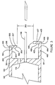
- a pair of locking arms is attached to the needle end of the barrel 103.
- the first arm 300 has a barrel end 301 and a needle end 302.
- the first arm 300 also has a an inner surface 303 and an outer surface 304.
- the longitudinal axis of the first arm 300 is substantially parallel to the longitudinal axis of the barrel 101.
- the second arm 400 has a barrel end 401 and a needle end 402.
- the second arm 400 also has an inner surface 403 and an outer surface 404.
- the second arm 400 is longer than the first arm 300. Arms 300 and 400 will typically be composed of molded plastic and be integrally attached to the barrel 101.
- a first detent 305 is attached to the needle end 302 of the first arm 300.
- the first detent 305 extends inward from the needle end 302 of the first arm 300 towards needle 108, and the longitudinal axis of the first detent 300 is substantially perpendicular to the longitudinal axis of the barrel 101.
- the first detent 305 has a barrel surface 306 and a needle surface 307.
- the first detent 305 also has an arm end 308 and a free end 309. The free end 309 of the first detent 305 is beveled so that the barrel surface 306 of the first detent 305 is shorter than the needle surface 307 of the first detent 305.
- a second detent 405 is attached to the needle end 402 of the second arm 400.
- the second detent 405 extends inward from the needle end 402 of the second arm 400 towards the needle 108, and the longitudinal axis of the second detent 405 is substantially perpendicular to the longitudinal axis of the barrel 101.
- the second detent 405 has a barrel surface 406 and a needle surface 407.
- the second detent 405 also has an arm end 408 and a free end 409.
- Detents 305 and 405 will typically be composed of molded plastic and be integrally attached to the arms 300 and 400, one to each arm.
- the free end 409 of the second detent 405 and the free end 309 of the first detent 305 define a detent gap 350.
- the distance from the needle end of the barrel 103 to the first detent 305 must be greater than or equal to the distance the sleeve 111 must move to reach the safe position.
- the difference between the distance from the second detent 405 to the needle end of the barrel 103 and the distance from the first detent 305 to the needle end of the barrel 103 must be at least the thickness of the lip unit 133 but may not be so great as to allow the sleeve 111 to slip off the pointed end 109 of the needle 108.
- a resilient base 130 is integrally attached to the connecting end 113 of the sleeve 111.
- the base 130 is conical in the embodiment shown; however, other geometrical designs may be substituted.
- the base 130 has a connecting end 131 and a sleeve end 132.
- a lip unit 133 integral with the base 130, extends from the connecting end 113 of the base 130.
- the lip unit 133 forms a ring, lip ring 134.
- Other obvious shapes for the lip unit 133 may be substituted for the ring shape.
- the lip unit 133 has a base edge 135 a free edge 136.
- the diameter of the lip ring 134 measured from the free edge 136 is greater than the width of the detent gap 350 but less than or equal to the distance between the inner surface 303 of the first arm 300 and the inner surface 404 of the second arm 400.
- the distance separating the elements comprising the lip unit 133 must conform to the requirements given here regarding diameter.
- the width of the lip unit 133 may be reduced so that the lip unit 133 may be passed through the detent gap 350 as the sleeve 111 is slidably positioned over the needle 108. At this point, the lip unit 133 is positioned between the needle end of the barrel 103 and the first detent 305.
- the connector 114 moves the sleeve 111 forward, it will move the base 130 and the lip unit 133 forward as well.
- the lip unit 133 will engage the barrel surface 306 of the first detent 305. Because the free end 309 of the first detent 305 is beveled, it will allow the lip unit 133 to pass. After the lip unit 133 has passed the first detent 305, the needle surface 307 of the first detent 305 will not allow the lip unit 133 to retreat. The barrel surface 406 of the second detent 405 will not allow the lip unit 133 to advance past it.
- the lip unit 133 is, thereby, locked between the first detent 305 and the second detent 405. Because the lip unit 133 is integrally attached to the base 130 which in turn is integrally attached to sleeve 111, the sleeve 111 is locked in the safe position.
- Safety syringe 100 is shipped in sterile packaging and normally will have a removable cover (not shown) over needle 108 and sleeve 111.
- the operator removes the removable cover and inserts needle 108 into a container of medication fluid.
- the operator pulls plunger 105 in a direction away from needle 108 so that the fluid is drawn into barrel 101 until washer end 107 is in alignment with the appropriate unit marks 202.
- the operator withdraws needle 108 from the container.
- the operator pushes the needle into the injection site on the patient. Once the needle is appropriately positioned in the patient, the operator pushes on thumb end 106 of plunger 105, applying enough force to move washer end 107 of plunger 105 past stop means 118 to needle end 103 of barrel 101.
- This movement causes sleeve 111 to move from the exposed position to the safe position while pointed end 109 of needle 108 is still in the patient.
- the operator removes safety syringe 100 from the patient and disposes of safety syringe 100.
- the operation for covering pointed end 109 of needle 108 is thus automatic with the administration of the injection and is a one-handed operation.
Landscapes
- Health & Medical Sciences (AREA)
- Engineering & Computer Science (AREA)
- Heart & Thoracic Surgery (AREA)
- Vascular Medicine (AREA)
- Anesthesiology (AREA)
- Biomedical Technology (AREA)
- Environmental & Geological Engineering (AREA)
- Hematology (AREA)
- Life Sciences & Earth Sciences (AREA)
- Animal Behavior & Ethology (AREA)
- General Health & Medical Sciences (AREA)
- Public Health (AREA)
- Veterinary Medicine (AREA)
- Infusion, Injection, And Reservoir Apparatuses (AREA)
Claims (14)
- Sicherheitsspritze (100) mit: einem hohlen Zylinder (101) mit einem Nadelende (103) und einem Stößelende (102), wobei sich ein Stößel (105) aus dem Zylinder erstreckt, der Stößel ein Daumenende (106) und ein Scheibenende (107) aufweist, wobei das Scheibenende so konfiguriert ist, daß es eine im wesentlichen fluiddichte Abdichtung zwischen dem Scheibenende und der Innenwand des Zylinders schafft, wobei sich eine Nadel (108) von dem Nadelende des Zylinders erstreckt und die Nadel ein spitzes Ende (109) und ein Zylinderende (110) aufweist, wobei eine Hülse (111) um die Nadel positioniert ist, wobei die Hülse entlang der Nadel zwischen einer Position, in der das spitze Ende der Nadel freiliegt, und einer Position, in der das spitze Ende abgedeckt ist, verschiebbar ist, und wobei die Spritze ferner einen Verbinder (114) mit einem Hülsenende und einem Zylinderende umfaßt und das Hülsenende des Verbinders mit einem Verbinderende der Hülse verbunden ist, wobei das Zylinderende des Verbinders verschiebbar durch eine Verbinderöffnung (104) am Nadelende (103) des Zylinders einsetzbar ist, wobei der Verbinder (114) und die Verbinderöffnung (104) so eingerichtet sind, daß ein Abschnitt des Verbinder-Zylinderendes in den Zylinder vorsteht, wobei der Verbinder und die Hülse so eingerichtet sind, daß der Verbinder (114), wenn sich das Scheibenende (107) des Stößels zu dem Nadelende (103) des Zylinders bewegt, die Hülse (111) von der freiliegenden Position zu der abgedeckten Position bewegt, wobei die Spritze dadurch gekennzeichnet ist, dass die Hülse durch Vorwärtsbewegen des Stößels bei der Verabreichung einer Injektion vor dem Entfernen der Nadel aus dem Patienten von der freiliegenden Position in die abgedeckten Position bewegt werden kann.
- Spritze nach Anspruch 1, wobei der Verbinder ein Rastelement aufweist, das sich an dem Verbinder-Zylinderende zwischen dem Scheibenende des Stößels und dem Zylinder-Nadelende befindet, um zu verhindern, daß der Verbinder (114) und die Hülse (111) aus dem Zylinder (101) gezogen werden.
- Spritze nach Anspruch 1, wobei das Rastelement eine Lippe an dem Verbinder-Zylinderende ist.
- Spritze nach Anspruch 2 oder 3, wobei das Rastelement eine Lippe ist, welche den Verbinder (114) vollständig umgibt.
- Spritze nach einem der vorangehenden Ansprüche, wobei der Verbinder aus einem länglichen starren oder halb-starren Material hergestellt ist.
- Spritze nach einem der vorangehenden Ansprüche, wobei die Spritze zwei Verbinder umfaßt.
- Spritze nach einem der Ansprüche 1 bis 5, wobei die Spritze drei oder mehr Verbinder umfaßt.
- Spritze nach einem der vorangehenden Ansprüche, wobei die Hülse (111) ein einheitliches Element mit einem Verbinder (114) bildet, so daß ein Niederdrücken des Stößels (105) auf den Verbinder (114) einwirkt, um die Hülse zu der abgedeckten Position zu bewegen.
- Spritze nach einem der vorangehenden Ansprüche, ferner mit einem Rastelement (121) an dem Zylinderende (116) des Verbinders (114), wobei das Rastelement so eingerichtet ist, daß das Rastelement mit dem Nadelende (103) des Zylinders (101) in Eingriff kommt, wenn sich der Stößel (105) zu dem Nadelende des Zylinders hin bewegt.
- Spritze nach einem der vorangehenden Ansprüche, ferner mit einer Durchgangstülle bzw. Durchführungsdichtung (120) zwischen dem Verbinder (114) und der Verbinderöffnung (104), wobei die Durchführungsdichtung, der Verbinder und die Verbinderöffnung so eingerichtet sind, daß sie eine fluiddichte Dichtung bilden.
- Spritze nach einem der vorangehenden Ansprüche, ferner mit einem oder mehreren Anschlagmittel(n) (118), das/die an der Innenwand (117) nahe dem Nadelende (103) des Zylinders (101) und zwischen dem Nadelende und dem Stößelende des Zylinders angebracht ist/sind, wobei das/die Anschlagmittel so eingerichtet ist/sind, dass es/sie mit dem Scheibenende in Eingriff kommen und dessen Bewegung zu dem Nadelende des Zylinders hin anhalten kann/können, wobei das/die Anschlagmittel ferner so eingerichtet ist/sind, daß das Scheibenende (101) bei Aufbringung einer ausreichenden Kraft auf den Stößel (105) durch die Bedienungsperson an dem/den Anschlagmitteln vorbeibewegt werden kann.
- Spritze nach Anspruch 11, wobei die Anschlagmittel (118) so positioniert sind, daß eine Bedienungsperson durch Bewegen des Stößels (105) zum Stößelende des Zylinders (101) hin Fluid in den Zylinder (101) ansaugen und Luft aus dem Fluid austreiben kann, indem der Stößel zu dem Nadelende des Zylinders gedrückt wird, ohne das Scheibenende (107) des Stößels über die Anschlagmittel hinaus zu bewegen.
- Spritze nach Anspruch 11, wobei der Zylinder (101) ferner Volumenmarkierungen zum Angeben der Fluidmenge, die in den Zylinder gesaugt worden ist, aufweist, wobei die Volumenmarkierungen eine Nullmarke und mindestens eine Einheitenmarke umfassen und die Nullmarke mit dem/den Anschlagmittel(n) ausgerichtet ist.
- Sicherheitsspritze nach Anspruch 1, mit
einem sich von dem Nadelende (103) des Zylinders (101) erstreckenden ersten Arm (300), wobei die Longitudinalachse des ersten Arms im wesentlichen parallel zu der Longitudinalachse des Zylinders ist und der erste Arm ein Zylinderende (301) und ein Nadelende (302) aufweist, und der erste Arm auch eine Innenfläche und eine Außenfläche aufweist,
einer ersten Arretierung (305), die sich von dem Nadelende des ersten Arms zu der Nadel hin nach innen erstreckt, wobei die Longitudinalachse der ersten Arretierung im wesentlichen senkrecht zu der Longitudinalachse des Zylinders ist,
wobei die erste Arretierung eine Zylinderfläche (306) und eine Nadelfläche (307) aufweist, und die erste Arretierung auch ein Armende (308) und ein freies Ende (309) aufweist, wobei das freie Ende der ersten Arretierung derart konisch bzw. abgeschrägt geformt ist, daß die Zylinderfläche der ersten Arretierung kürzer als die Nadelfläche der ersten Arretierung ist,
einem zweiten Arm (400), der sich von dem Nadelende des Zylinders erstreckt, wobei die Longitudinalachse des zweiten Arms im wesentlichen parallel zu der Longitudinalachse des Zylinders ist und der zweite Arm ein Zylinderende (401) und ein Nadelende (402) aufweist, der zweite Arm auch eine Innenfläche (403) und eine Außenfläche (404) aufweist, der zweite Arm länger als der erste Arm ist, und das Zylinderende des zweiten Arms an bzw. auf dem Nadelende des Zylinders derart positioniert ist, daß sich die Verbinderöffnung zwischen dem Zylinderende des zweiten Arms und dem Zylinderende des ersten Arms befindet,
einer zweiten Arretierung (405), die sich von dem Nadelende des zweiten Arms zu der Nadel nach innen erstreckt, wobei die Longitudinalachse der zweiten Arretierung im wesentlichen senkrecht zu der Longitudinalachse des Zylinders ist, die zweite Arretierung eine Zylinderfläche (406) und eine Nadelfläche (407) aufweist, die zweite Arretierung auch ein Armende (408) und ein freies Ende (409) aufweist und das freie Ende der zweiten Arretierung zusammen mit dem freien Ende der ersten Arretierung einen Arretierungsspalt festlegt,
einer elastischen Basis (130), die sich von dem Verbinderende der Hülse erstreckt, wobei die Basis ein Verbindungsende (131) und ein Hülsenende (132) aufweist,
einer Lippe, die sich von dem Verbindungsende der Basis im wesentlichen senkrecht zu der Longitudinalachse der Hülse nach außen erstreckt, wodurch eine Lippeneinheit (133) gebildet wird, wobei die Lippeneinheit einen Basisrand (135) und einen freien Rand (136) aufweist und die Lippeneinheit so eingerichtet ist, daß die Lippeneinheit durch Aufbringen eines einwärts gerichteten Drucks auf die elastische Basis durch den Arretierungsspalt passieren kann, wenn die Hülse verschiebbar über der Nadel positioniert ist bzw. wird, wodurch die Lippeneinheit zwischen der ersten Arretierung und dem Nadelende des Zylinders positioniert werden kann,
einem Verbinder (114) mit einem Hülsenende und einem Zylinderende, wobei das Hülsenende des Verbinders funktionsmäßig mit dem Verbindungsende der Hülse und der Basis verbunden ist, wobei das Zylinderende des Verbinders verschiebbar durch die Verbinderöffnung einsetzbar ist, wobei der Verbinder und die Verbinderöffnung so eingerichtet sind, daß ein Abschnitt des Zylinderendes des Verbinders in den Zylinder hineinsteht, wobei der Verbinder und die Hülse so eingerichtet sind, daß, wenn sich das Scheibenende des Stößels zu dem Nadelende des Zylinders bewegt, der Verbinder die Hülse von der freiliegenden Position zu der sicheren Position bewegt, und wobei der Verbinder, die Hülse, die Basis und die Lippeneinheit ferner so eingerichtet sind, daß, nachdem der Verbinder die Hülse in die sichere Position bewegt hat, der Verbinder die sich von der Basis erstreckende Lippeneinheit an dem konischen bzw. abgeschrägten freien Ende der ersten Arretierung vorbei bewegt, wodurch die Lippeneinheit zwischen der Nadeloberfläche der ersten Arretierung und der Zylinderfläche der zweiten Arretierung verriegelt, wodurch die Hülse in der sicheren Position verriegelt ist bzw. wird.
Applications Claiming Priority (3)
| Application Number | Priority Date | Filing Date | Title |
|---|---|---|---|
| US301541 | 1994-09-06 | ||
| US08/301,541 US5460611A (en) | 1994-09-06 | 1994-09-06 | Safety syringe |
| PCT/US1995/011426 WO1996007439A1 (en) | 1994-09-06 | 1995-09-06 | A safety syringe |
Publications (3)
| Publication Number | Publication Date |
|---|---|
| EP0909189A4 EP0909189A4 (de) | 1999-04-21 |
| EP0909189A1 EP0909189A1 (de) | 1999-04-21 |
| EP0909189B1 true EP0909189B1 (de) | 2004-04-07 |
Family
ID=23163826
Family Applications (1)
| Application Number | Title | Priority Date | Filing Date |
|---|---|---|---|
| EP95933756A Expired - Lifetime EP0909189B1 (de) | 1994-09-06 | 1995-09-06 | Sicherheitsspritze |
Country Status (6)
| Country | Link |
|---|---|
| US (2) | US5460611A (de) |
| EP (1) | EP0909189B1 (de) |
| AU (1) | AU3628495A (de) |
| CA (1) | CA2199176A1 (de) |
| DE (1) | DE69532869T2 (de) |
| WO (1) | WO1996007439A1 (de) |
Families Citing this family (37)
| Publication number | Priority date | Publication date | Assignee | Title |
|---|---|---|---|---|
| FR2736553B1 (fr) * | 1995-07-12 | 1998-01-09 | Soc Et Et D Applic Tech Sedat | Seringue d'injection, notamment de produits medicaux liquides, a protecteur d'aiguille mobile |
| US5785662A (en) * | 1996-05-30 | 1998-07-28 | Medisys Technologies, Inc. | Blood collection assembly with plurality of vials |
| SE513823C2 (sv) * | 1996-05-31 | 2000-11-13 | Wiklund Ernst S G F | Spetsskydd för punktionsnålar |
| US5846228A (en) * | 1996-11-14 | 1998-12-08 | Medisys Technologies, Inc. | Safety syringe for fluid collection |
| US5951520A (en) | 1996-12-19 | 1999-09-14 | Bio-Plexus, Inc. | Self-blunting needle medical devices and methods of manufacture thereof |
| US6059758A (en) * | 1997-10-15 | 2000-05-09 | Merit Medical Systems, Inc. | Prophylactic sheath for protecting and storing different types of medical needles |
| IE970782A1 (en) * | 1997-10-22 | 1999-05-05 | Elan Corp | An improved automatic syringe |
| US5993418A (en) * | 1998-02-24 | 1999-11-30 | Medisys Technologies, Inc. | Safety syringe |
| DE29822031U1 (de) * | 1998-12-10 | 1999-04-01 | Dräger Sicherheitstechnik GmbH, 23560 Lübeck | Vorrichtung zur Wischprobenahme und Probenverdünnung |
| US6832992B2 (en) * | 2000-03-07 | 2004-12-21 | Becton, Dickinson And Company | Passive safety device for needle of blood collection set |
| FR2816216B1 (fr) * | 2000-11-03 | 2003-09-05 | Sedat | Seringue d'injection a protecteur d'aiguille deplacable |
| US6626863B1 (en) * | 2000-11-22 | 2003-09-30 | Nusaf, L.L.C. | Safety syringe |
| MXPA03005518A (es) | 2000-12-22 | 2004-10-14 | Nicodel S A | Dispositivo medico y mecanismo de trabamiento para el mismo. |
| US20030050608A1 (en) * | 2001-09-12 | 2003-03-13 | Robert Brown | Passive fluid collection device |
| US7354422B2 (en) * | 2001-09-26 | 2008-04-08 | B. Braun Melsungen Ag | Spring launched needle safety clip |
| US6623458B2 (en) * | 2001-09-26 | 2003-09-23 | B. Braun Melsungen, Ag | Spring launched needle safety clip |
| US6984223B2 (en) | 2001-11-13 | 2006-01-10 | Becton, Dickinson And Company | Needle safety device |
| UA53537C2 (en) * | 2002-07-15 | 2005-01-17 | Amtech Ltd Ukrainian German Jo | Injection syringe |
| US7338474B2 (en) * | 2003-02-18 | 2008-03-04 | Tribute Technologies, Llc | Luer attachment for syringe safety |
| US20050015048A1 (en) * | 2003-03-12 | 2005-01-20 | Chiu Jessica G. | Infusion treatment agents, catheters, filter devices, and occlusion devices, and use thereof |
| US7250041B2 (en) | 2003-03-12 | 2007-07-31 | Abbott Cardiovascular Systems Inc. | Retrograde pressure regulated infusion |
| US20050027255A1 (en) | 2003-07-31 | 2005-02-03 | Sid Technologies, Llc | Automatic injector |
| IL157981A (en) | 2003-09-17 | 2014-01-30 | Elcam Medical Agricultural Cooperative Ass Ltd | Auto-injector |
| IL160891A0 (en) | 2004-03-16 | 2004-08-31 | Auto-mix needle | |
| EP1791583A4 (de) * | 2004-07-16 | 2016-08-17 | Unitract Syringe Pty Ltd | Spritzennadelhülle |
| CN100544784C (zh) * | 2005-04-26 | 2009-09-30 | 刘文杰 | 针头回缩式注射器的筒式推杆及针头回缩可控式注射器 |
| US20070016145A1 (en) * | 2005-06-09 | 2007-01-18 | Devon Safety Products, Inc. | Needle assembly for multiple syringe barrels |
| US20070016140A1 (en) * | 2005-06-09 | 2007-01-18 | Devon Safety Products, Inc. | Exchangeable safety needle assembly |
| US7798994B2 (en) * | 2005-11-15 | 2010-09-21 | Becton, Dickinson And Company | Needle shield to septum interconnect |
| US8057431B2 (en) | 2006-12-21 | 2011-11-15 | B. Braun Melsungen Ag | Hinged cap for needle device |
| US8439870B2 (en) | 2008-09-10 | 2013-05-14 | B. Braun Medical Inc. | Safety needle assembly and methods |
| GB2529621B (en) | 2014-08-21 | 2016-12-07 | Owen Mumford Ltd | Safety syringe |
| US10980950B2 (en) * | 2018-10-25 | 2021-04-20 | Sharps Technology Inc. | Ultra-low waste needle and syringe system that automatically and passively renders a needle safe during the injection process |
| US11154663B2 (en) | 2018-10-25 | 2021-10-26 | Sharps Technology Inc. | Pre-filled safety needle and syringe system |
| US12544516B2 (en) | 2019-06-27 | 2026-02-10 | Plasto Technology Group Llc | Ultra-low waste disposable syringe with self-adjusting integrated safety features |
| US11497860B2 (en) | 2019-06-27 | 2022-11-15 | Sharps Technology, Inc. | Ultra-low waste disposable safety syringe for low dose injections |
| US12589211B2 (en) | 2021-01-29 | 2026-03-31 | Plasto Technology Group Llc | Needle and syringe system with automatic safety shield that renders a needle safe |
Family Cites Families (59)
| Publication number | Priority date | Publication date | Assignee | Title |
|---|---|---|---|---|
| US3094122A (en) * | 1961-01-18 | 1963-06-18 | Theophile E Gauthier | Flexible cannula and intravenous needle combined |
| US4197846A (en) * | 1974-10-09 | 1980-04-15 | Louis Bucalo | Method for structure for situating in a living body agents for treating the body |
| US4026287A (en) * | 1975-12-10 | 1977-05-31 | Irene Haller | Syringe with retractable cannula |
| US4464171A (en) * | 1982-03-29 | 1984-08-07 | Garwin Mark J | Intravascular insertion apparatus and method |
| US4425120A (en) * | 1982-04-15 | 1984-01-10 | Sampson Norma A | Shielded hypodermic syringe |
| US4636202A (en) * | 1984-07-27 | 1987-01-13 | Syntex (U.S.A.) Inc. | Medicament applicator with plunger assembly and automatically-openable closure therefor |
| US4581021A (en) * | 1985-01-28 | 1986-04-08 | Ergomed | Squeeze-actuated syringe |
| EP0201611A1 (de) * | 1985-05-10 | 1986-11-20 | B. Braun-SSC AG | Zwei-Kanülen-Spritze |
| JPH0613052B2 (ja) * | 1985-11-08 | 1994-02-23 | デイゼトロニツク アクチエンゲゼルシヤフト | 注射装置 |
| US4702738A (en) * | 1986-05-22 | 1987-10-27 | Spencer Treesa A | Disposable hypodermic syringe and needle combination having retractable, accident preventing sheath |
| DE3680919D1 (de) * | 1986-10-09 | 1991-09-19 | Hakko Electric Machine Works C | Doppelnadel-set zum injizieren eines fluessigen medikaments. |
| FR2609885B1 (fr) * | 1987-01-22 | 1989-04-14 | Cassou Robert | Instrument pour l'insemination artificielle, le transfert d'embryons ou le prelevement de liquides folliculaires chez les mammiferes |
| JPS648468A (en) * | 1987-06-30 | 1989-01-12 | Keyence Co Ltd | Address specification system |
| CH673775A5 (de) * | 1987-07-10 | 1990-04-12 | Jacques Verlier | |
| US4976701A (en) * | 1987-09-25 | 1990-12-11 | Nordisk Gentofte A/S | Injection apparatus |
| US4874382A (en) * | 1987-10-15 | 1989-10-17 | Servetus Partnership | Safety syringe |
| US4892107A (en) * | 1988-01-05 | 1990-01-09 | Habley Medical Technology Corp. | Single use, safety blood collection device |
| US4863434A (en) * | 1988-01-29 | 1989-09-05 | Bayless William B | Automatic needle sheath for disposable syringe |
| US4820277A (en) * | 1988-02-16 | 1989-04-11 | Norelli Robert A | Safety cover for syringe needles |
| US4935016A (en) * | 1988-02-17 | 1990-06-19 | Deleo John | Syringe |
| US4850996A (en) * | 1988-02-22 | 1989-07-25 | Cree Ian C | Safety needle |
| US4923445A (en) * | 1988-03-01 | 1990-05-08 | Ryan Medical, Inc. | Safety needled medical devices |
| US4875895A (en) * | 1988-03-16 | 1989-10-24 | Minnesota Mining And Manufcturing | Buffing apparatus for book-fold carton; and method |
| US4935014A (en) * | 1988-06-24 | 1990-06-19 | Habley Medical Technology Corporation | Combination retractable needle cannual and cannual lock for a medication carpule |
| US4978344A (en) * | 1988-08-11 | 1990-12-18 | Dombrowski Mitchell P | Needle and catheter assembly |
| US4883471A (en) * | 1988-08-16 | 1989-11-28 | Braginetz Paul A | Disposable shielded medical syringe |
| US4863435A (en) * | 1988-08-24 | 1989-09-05 | Sturman Martin F | Safety hypodermic syringe |
| US4875896A (en) * | 1988-08-29 | 1989-10-24 | Kurtz Sharon L | Needle disposal device and method for preventing accidental contact with a needle |
| CA1315166C (en) * | 1988-10-05 | 1993-03-30 | John S. Parry | Injection devices |
| US4969877A (en) * | 1988-10-19 | 1990-11-13 | The Pascall Medical Corporation | Syringe |
| US4929237A (en) * | 1988-11-07 | 1990-05-29 | David Medway | Hypodermic needle protection device |
| US4894055A (en) * | 1988-12-28 | 1990-01-16 | Sudnak Paul J | Needle guard assembly for use with hypodermic syringes and the like |
| US5032117A (en) * | 1989-01-30 | 1991-07-16 | Motta Louis J | Tandem syringe |
| US4944723A (en) * | 1989-02-02 | 1990-07-31 | Habley Medical Technology Corporation | Universal disposable safety syringe system |
| US4966593A (en) * | 1989-03-06 | 1990-10-30 | Design Specialties Laboratories | Disposable hypodermic syringe with retractable needle |
| US4966592A (en) * | 1989-05-05 | 1990-10-30 | Burns Cameron A | Protective sleeve for hypodermic needle |
| US4973317A (en) * | 1989-07-14 | 1990-11-27 | Bobrove Arthur M | Automatic sheath protection of hypodermic needle |
| US5205825A (en) * | 1989-08-07 | 1993-04-27 | Allison Alan C | Insertable element for preventing reuse of plastic syringes |
| US4986819A (en) * | 1989-09-26 | 1991-01-22 | Daniel Sobel | Pressure sensitive needle guard |
| US4973316A (en) * | 1990-01-16 | 1990-11-27 | Dysarz Edward D | One handed retractable safety syringe |
| US5015240A (en) * | 1990-05-01 | 1991-05-14 | Ian Campbell Cree | Hypodermic needle shield |
| US5135507A (en) * | 1990-05-10 | 1992-08-04 | Habley Medical Technology Corporation | One-piece syringe |
| US4982842A (en) * | 1990-06-04 | 1991-01-08 | Concord/Portex | Safety needle container |
| US5026353A (en) * | 1990-06-25 | 1991-06-25 | Bartman Thomas F | Multi-chamber safety syringe |
| US5051109A (en) * | 1990-07-16 | 1991-09-24 | Simon Alexander Z | Protector for catheter needle |
| US5067942A (en) * | 1990-12-20 | 1991-11-26 | The Board Of Trustees Of The Leland Stanford Junior University | Single use hypodermic needle |
| US5092851A (en) * | 1991-01-04 | 1992-03-03 | Ragner & Staab Associates | Safety needle with spring-loaded shield |
| US5098401A (en) * | 1991-01-04 | 1992-03-24 | Lange Andries G De | Disposable automatic needle cover assembly with safety lock |
| US5122123A (en) * | 1991-01-30 | 1992-06-16 | Vaillancourt Vincent L | Closed system connector assembly |
| US5092852A (en) * | 1991-02-15 | 1992-03-03 | Edward Poling | Safety syringe for single use |
| US5306258A (en) * | 1991-04-03 | 1994-04-26 | Fuente Ricardo L De | Safety syringe and method of using same |
| US5370628A (en) * | 1991-07-31 | 1994-12-06 | Allison; Alan C. | Safety needle and syringe |
| US5151088A (en) * | 1991-07-31 | 1992-09-29 | The Board Of Trustees Of The Leland Stanford Junior University | Safety needle and syringe assembly |
| FR2687578B1 (fr) * | 1992-02-26 | 1994-04-15 | Daniel Dutartre | Dispositif pour augmenter la precision des seringues. |
| US5282792A (en) * | 1992-07-21 | 1994-02-01 | Becton, Dickinson And Company | Syringe having two component barrel |
| US5385555A (en) * | 1993-01-08 | 1995-01-31 | Becton, Dickinson And Company | Lockable safety shield for hypodermic syringe |
| US5342320A (en) * | 1993-01-15 | 1994-08-30 | Cameron Robert W | Hypodermic syringe having shielding to prevent accidental injury following use |
| US5314503A (en) * | 1993-03-23 | 1994-05-24 | Rasor Associates, Inc. | Automatic sheath protection of hypodermic needle |
| US5300038A (en) * | 1993-04-30 | 1994-04-05 | Habley Medical Technology Corporation | Safety syringe with off-axis needle cannula |
-
1994
- 1994-09-06 US US08/301,541 patent/US5460611A/en not_active Expired - Fee Related
-
1995
- 1995-09-06 WO PCT/US1995/011426 patent/WO1996007439A1/en not_active Ceased
- 1995-09-06 DE DE69532869T patent/DE69532869T2/de not_active Expired - Fee Related
- 1995-09-06 CA CA002199176A patent/CA2199176A1/en not_active Abandoned
- 1995-09-06 EP EP95933756A patent/EP0909189B1/de not_active Expired - Lifetime
- 1995-09-06 AU AU36284/95A patent/AU3628495A/en not_active Abandoned
-
1996
- 1996-10-08 US US08/727,756 patent/US5720727A/en not_active Expired - Fee Related
Also Published As
| Publication number | Publication date |
|---|---|
| US5720727A (en) | 1998-02-24 |
| DE69532869D1 (de) | 2004-05-13 |
| MX9701608A (es) | 1998-05-31 |
| EP0909189A4 (de) | 1999-04-21 |
| US5460611A (en) | 1995-10-24 |
| AU3628495A (en) | 1996-03-27 |
| WO1996007439A1 (en) | 1996-03-14 |
| CA2199176A1 (en) | 1996-03-14 |
| DE69532869T2 (de) | 2005-03-03 |
| EP0909189A1 (de) | 1999-04-21 |
Similar Documents
| Publication | Publication Date | Title |
|---|---|---|
| US5460611A (en) | Safety syringe | |
| US20230330387A1 (en) | Retractable needle catheter insertion device | |
| US6004296A (en) | Lockable safety shield assembly for a prefillable syringe | |
| US7060055B2 (en) | Forward shielding safety device | |
| US5697908A (en) | Lockable safety shield for a prefillable syringe | |
| EP1654021B1 (de) | Pen-anordnung zur arzneiabgabe mit nadelarretierendem sicherheitsschutz | |
| US7422573B2 (en) | Forward blunting wingset with leaf spring driven shield | |
| CN105592876B (zh) | 安全针设备 | |
| JP2739840B2 (ja) | 片手で操作可能な針バリヤを有する針組立体 | |
| US4946447A (en) | Protective cover for hypodermic needle | |
| US6626864B2 (en) | Safety shield system for prefilled syringes | |
| US5176656A (en) | Automatically positioned needle sheath for a disposable hypodermic syringe | |
| US8313470B2 (en) | Autoinjector | |
| EP1362608B1 (de) | Nadelschutzvorrichtung | |
| US5476106A (en) | Method of destroying and storing used cannulas | |
| US7201740B2 (en) | Forward-shielding blood collection set | |
| US8109905B2 (en) | Retractable needle assembly | |
| KR910008024B1 (ko) | 한손으로 조정가능한 안전바늘 의료 장치 | |
| EP1449560A1 (de) | Medizinisches Gerät mit Schirm und zurückziehbarer Nadel | |
| US5360409A (en) | Syringe holder with retractable needle assembly | |
| JPH10127767A (ja) | 片手操作可能な針バリアーを備えた針アセンブリ | |
| WO2014077831A1 (en) | Passive double drive member activated safety blood collection device | |
| CN112292079A (zh) | 挤压致动的血液收集套件 | |
| MXPA97001608A (en) | A syringe of seguri |
Legal Events
| Date | Code | Title | Description |
|---|---|---|---|
| PUAI | Public reference made under article 153(3) epc to a published international application that has entered the european phase |
Free format text: ORIGINAL CODE: 0009012 |
|
| 17P | Request for examination filed |
Effective date: 19970404 |
|
| A4 | Supplementary search report drawn up and despatched |
Effective date: 19980327 |
|
| AK | Designated contracting states |
Kind code of ref document: A4 Designated state(s): DE FR GB IT Kind code of ref document: A1 Designated state(s): DE FR GB IT |
|
| 17Q | First examination report despatched |
Effective date: 20011008 |
|
| GRAH | Despatch of communication of intention to grant a patent |
Free format text: ORIGINAL CODE: EPIDOS IGRA |
|
| GRAS | Grant fee paid |
Free format text: ORIGINAL CODE: EPIDOSNIGR3 |
|
| GRAA | (expected) grant |
Free format text: ORIGINAL CODE: 0009210 |
|
| AK | Designated contracting states |
Kind code of ref document: B1 Designated state(s): DE FR GB IT |
|
| REG | Reference to a national code |
Ref country code: GB Ref legal event code: FG4D |
|
| RAP2 | Party data changed (patent owner data changed or rights of a patent transferred) |
Owner name: NUSAF, L.L.C. |
|
| RIN2 | Information on inventor provided after grant (corrected) |
Inventor name: NUSAF, L.L.C. |
|
| REF | Corresponds to: |
Ref document number: 69532869 Country of ref document: DE Date of ref document: 20040513 Kind code of ref document: P |
|
| ET | Fr: translation filed | ||
| PLBE | No opposition filed within time limit |
Free format text: ORIGINAL CODE: 0009261 |
|
| STAA | Information on the status of an ep patent application or granted ep patent |
Free format text: STATUS: NO OPPOSITION FILED WITHIN TIME LIMIT |
|
| 26N | No opposition filed |
Effective date: 20050110 |
|
| PGFP | Annual fee paid to national office [announced via postgrant information from national office to epo] |
Ref country code: FR Payment date: 20050823 Year of fee payment: 11 |
|
| PGFP | Annual fee paid to national office [announced via postgrant information from national office to epo] |
Ref country code: DE Payment date: 20060331 Year of fee payment: 11 |
|
| PGFP | Annual fee paid to national office [announced via postgrant information from national office to epo] |
Ref country code: IT Payment date: 20060930 Year of fee payment: 12 |
|
| PG25 | Lapsed in a contracting state [announced via postgrant information from national office to epo] |
Ref country code: DE Free format text: LAPSE BECAUSE OF NON-PAYMENT OF DUE FEES Effective date: 20070403 |
|
| GBPC | Gb: european patent ceased through non-payment of renewal fee |
Effective date: 20060906 |
|
| REG | Reference to a national code |
Ref country code: FR Ref legal event code: ST Effective date: 20070531 |
|
| PG25 | Lapsed in a contracting state [announced via postgrant information from national office to epo] |
Ref country code: GB Free format text: LAPSE BECAUSE OF NON-PAYMENT OF DUE FEES Effective date: 20060906 |
|
| PG25 | Lapsed in a contracting state [announced via postgrant information from national office to epo] |
Ref country code: FR Free format text: LAPSE BECAUSE OF NON-PAYMENT OF DUE FEES Effective date: 20061002 |
|
| PGFP | Annual fee paid to national office [announced via postgrant information from national office to epo] |
Ref country code: GB Payment date: 20060330 Year of fee payment: 11 |
|
| PG25 | Lapsed in a contracting state [announced via postgrant information from national office to epo] |
Ref country code: IT Free format text: LAPSE BECAUSE OF NON-PAYMENT OF DUE FEES Effective date: 20070906 |