EP0909098A2 - Vorrichtung zur Bewegungsvektordetektion - Google Patents
Vorrichtung zur Bewegungsvektordetektion Download PDFInfo
- Publication number
- EP0909098A2 EP0909098A2 EP98118474A EP98118474A EP0909098A2 EP 0909098 A2 EP0909098 A2 EP 0909098A2 EP 98118474 A EP98118474 A EP 98118474A EP 98118474 A EP98118474 A EP 98118474A EP 0909098 A2 EP0909098 A2 EP 0909098A2
- Authority
- EP
- European Patent Office
- Prior art keywords
- motion vector
- block
- search area
- blocks
- vector detecting
- Prior art date
- Legal status (The legal status is an assumption and is not a legal conclusion. Google has not performed a legal analysis and makes no representation as to the accuracy of the status listed.)
- Granted
Links
Images





Classifications
-
- H—ELECTRICITY
- H04—ELECTRIC COMMUNICATION TECHNIQUE
- H04N—PICTORIAL COMMUNICATION, e.g. TELEVISION
- H04N19/00—Methods or arrangements for coding, decoding, compressing or decompressing digital video signals
- H04N19/50—Methods or arrangements for coding, decoding, compressing or decompressing digital video signals using predictive coding
- H04N19/503—Methods or arrangements for coding, decoding, compressing or decompressing digital video signals using predictive coding involving temporal prediction
- H04N19/51—Motion estimation or motion compensation
Definitions
- the present invention relates to a motion vector detecting device used for motion picture encoding.
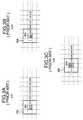
- Detection of motion vectors is accomplished by using block matching operation in motion picture compression techniques such as MPEG. This involves block matching between a block 103 in an object frame 101 to be encoded (hereinafter referred to as object block) and a block in a search area 104 in the other reference frame 102, both blocks being separated from each other with respect to time and detecting the relative position of the blocks having the highest correlation as a motion vector 105 as shown in Fig. 1.
- search area the necessary range of reference pixels
- AEk denotes the evaluation value.
- the values are determined in the search area.
- the position of block which assumes the minimum value among the values is determined as a motion vector.
- Encoding of frame is conducted by sequentially performing such processing for the object block.
- Fig. 2 is a block diagram showing the prior art.
- the pixels of an object are input from 201 and are temporarily stored in an object peel memory 202.
- the pixels of a reference frame are input from 203 and are stored in reference pixel memories 204 through 205.
- n denotes the number of ME circuits.
- Vector detection is carried out by providing the pixel data to motion vector detecting circuits (hereinafter abbreviated as "ME circuit") 206 to 207 according to a predetermined sequence.
- ME circuit motion vector detecting circuits
- the minimum value of AE is ultimately determined as a motion vector by a vector selecting circuit 208 and is output from 209.
- each of the ME circuits be capable of conducting vector detection in a search area of 3m by 3m pixels for a block of m by m pixels.
- a half tone dotted block in Fig. 3 denotes an object block and the area which is encircled by a solid line around the object block is a search area.
- Motion vector detection is conducted by controlling the device to apply the object block data and the search area data to the ME circuit 206.
- the motion vector for the object block 301 in position i is detected at its periphery 302.
- the motion vector for the object block 303 in position i+1 is detected in its peripheral search area 304 as shown in Fig. 3B.
- motion vectors will be successively determined for blocks in position i+2, i+3, .... so on.
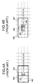
- the object block is a netted block 401 as is similarly to the former case.
- the search area is widened by assign the search area to each of two ME circuits.
- the whole search area 202 is divided into sub-search areas 403 and 404.
- the respective data are separately applied to ME circuits 206 and 207 from the reference pixel memories 204 and 205 in Fig. 2, respectively.
- the data of the object block 401 is simultaneously applied to both ME circuits from the object pixel memory 202.
- Motion vectors of difference search areas can be determined by respective circuits.
- the motion vectors and the evaluation values of the block matching are input to the vector selecting circuit 208 and a motion vector having less evaluation value is ultimately output from 209.
- the above-mentioned operation allows the motion vector to be detected from a search area having 5m by 3m pixels for the object block of m by m pixels.
- the search areas 403 and 404 partially overlap with each other. It is seemed that an area which is wider by one block width could be covered if the search areas are assigned so that they do not overlap with each other as shown in Fig. 4B. Such assignment is impossible since motion vector detection can not be performed for a candidate block in position 409.
- the right end position of the candidate block in the left sub-search area 405 is a position in 406 and the left end position of the candidate block in the right sub-search area 407 is a position 408 and thus detection of motion vector would not performed for either sub-search area, for example, for the candidate block in position 409.
- Motion vectors can be detected from a wider search area than that in Figs. 3A to 3C by successively repeating the above-mentioned operation for each object block as is similarly to Figs. 3A to 3C.
- a motion vector detecting device which is based upon the above-mentioned concept is disclosed in Japanese laid-Open Patent Publication No. 7-288818.
- widening of search area is achieved by dividing the search area into four sub-areas, applying respective data on the sub-areas to respective different ME circuits and applying data on object blocks to respective ME circuits while delaying them appropriately, resulting in reduction in hardware.
- the memory capacity increases in proportion with the search area since it is necessary to store all pixel data of the search areas in memories. Since a longer period of time is taken for the pixel data to be transferred to a reference pixel memory, longer period of time for processing is required.
- It is an object of the present invention to provide with a motion vector detecting device comprising an object pixel memory for holding pixels of an object block to be encoded; a reference pixel memory for holding pixels of a search area of a reference frame; a plurality of motion vector detecting circuit having a predetermined search area; and a motion vector selecting circuit for selecting an optimal motion vector from the outputs from said motion vector detecting circuits, and characterized in that the pixel data of different object block are applied to the plurality of vector detecting circuits from said object pixel memory, in that the pixel data of the predetermined search area are commonly applied to all motion vector detecting circuit from said reference pixel memory, whereby a motion vector can be detected in a wider area by selecting/comparing output from the plurality of motion vector detecting circuits by said motion vector selecting circuit in an appropriate timing relationship.
- the mode of embodying the invention will be described.
- An embodiment in which the object block comprises m by m pixels, and the range of the search area comprising 3m by 3m pixels as is similarly to the prior art is detected by one ME circuit will be described.
- Fig. 5 is a block diagram showing a first embodiment of the present invention.
- the pixels of an object block which are input from an object pixel input 501 are stored in an object pixel memory 502.
- Reference pixels of search area which are input from a reference pixel input 503 are stored in a reference pixel memory 504.
- the appropriately necessary pixel data are applied to ME circuits 507 to 508 from these pixel memories and the detected motion vectors and the block matching evaluation values are input to a vector selecting circuit 505 and the least evaluation value is output as a final result from a motion vector output 506.
- widening of the search area is achieved by simultaneously applying the same reference pixel data of the search area stored in the reference pixel memory 504 to respective ME circuits and applying data in different block positions to respective ME circuits as pixel data of an object block.
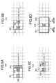
- FIG. 6A to 6C The relation between the object block and the search area and its changes with time is shown in Figs. 6A to 6C.
- a search area for one object block (block i+2) is shown in Fig. 6D.
- halftone dotted block (except 613) is the object block and a square surrounding the object block which is represented by a solid line is the search area.
- the search area for an object block has the dimension 5m by 3m (610) in Fig. 6D which is divided into two sub-search areas 611 and 612, each having 3m by 3m, which partially overlap. Motion vector detection for respective sub-search areas is conducted at different times in different ME circuits.
- sequential operation comprises simultaneously applying pixel data of sub-search areas, each having 3m by 3m to respective ME circuits and then applying pixel data in position of halftone dotted object block to separately to respective ME circuits.
- motion vector detection in the same range of the left sub-search area 601 of the object block 603 is conducted in the ME circuit 508 for the object block 603 in position i+2.
- motion vector detection is conducted in position at which both object block and sub-search area is shifted rightward by one block.
- Motion vector detection in the range of right sub-search area 604 for the object block 605 is conducted in ME circuit 507 for the object block 605 in position i+1.
- Motion vector detection in the same range of left sub-search area 604 for the object block 606 is conducted in ME circuit 508 for the object block 606 in position i+3.
- the pixel data of the sub-search area which is newly necessary when the sub-search area is shifted rightward by one block is only that at area 613. Accordingly, the pixel data which is to be newly input to the reference pixel memory 504 is only 3 by (m by m).
- Motion vector detection in the range of right sub-search area 607 for the object block 608 is conducted in ME circuit 507 for the object block 608 in position i+2.
- Motion vector detection in the range of left sub-search area 607 for the object block 609 is conducted in ME circuit 508 for the object block 609 in position i+4.
- Fig. 7 shows which object block the motion vector detection is conducted for in each ME circuit at respective times.
- t(701) denotes the time which is taken to process one block.
- An object block i+2 will be considered.
- the motion vector detection in the left sub-search area is performed by ME circuit 508.
- the motion vector detection at the right sub-search area is performed in ME circuit 507.
- comparison between the block matching evaluation value which is a result of the ME circuit 508 and the block matching evaluation value which is a result of the ME circuit 507 determines which or the motion vectors of the ME circuits should be output as an ultimate result.
- the vector selecting circuit may comprise an input 801, to which the motion vector from the ME circuit 507 and the block matching evaluation value are input, an input 802 to which the motion vector from the ME circuit 508 and the block matching evaluation value are input, a delay 803 for delaying the motion vector and the block matching evaluation value, a comparing and determining circuit 804 which compares the block matching evaluation values with each other to select the motion vector having less value and a motion vector output 805.
- the reason why the delay 803 is provided is that the time when the motion vector detection is performed is different between the right and left sub-search areas for a given object block as mentioned above.
- Delaying the motion vector and the block matching evaluation value by the time of 2t by this delay enables the results of the motion vector detection of right and left search areas for the same object block to be compared with each other.
- present embodiment intends to widen the search area in a horizontal direction, widening of the search area in a vertical direction is made possible by making the delay 2t into 2tH.
- Designation tH denotes a period of time which is taken to process one column of the object block in a horizontal direction.
- Fig. 9 shows the configuration of the second embodiment.
- the configuration is identical with that in Fig. 5 except that the number of ME circuits increases to 4. Thus, description of each component will be omitted.
- the search area is widened vertically or horizontally by using four ME circuits.
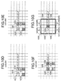
- Figs. 10A to 10G show the relation between the object block and the search area its sequential changes and the search areas for a given block.
- Designation tH denotes a period of time which is taken to process one column of the object block in a horizontal direction.
- An object block 1031 in position i+2 in the present embodiment will be considered.
- the search area 1032 has a dimension of 5m by 5m.
- the search area is divided into four sub-search areas 1033, 1034, 1035 and 1036, the motion vectors of which are detected by respective different ME circuits at different times.
- the sub-search area 1033 is suffixed with UL since it is in the upper and left area as viewed from the object block and 1034, 1035 and 1036 are suffixed with UR, DL and DR since they are in the upper and right area, lower and left area, and lower and right area, respectively.
- Figs. 10A to 10F Sequential operation is illustrated in Figs. 10A to 10F.
- the pixel data of the sub-search area 1001 is simultaneously provided to ME circuits 907 to 910 from the reference pixel memory 904.
- the pixel data of the object block are provided to ME circuit from the object pixel memory 902.
- the pixel data of the object block 1002 are provided to the ME circuit 909 and the sub-search area 1001 is used as the lower and right (DR) sub-search area for the object block 1002 so that the motion vector detection is performed.
- the pixel data of the object block 1003 are provided to ME circuit 910 and the sub-search area is used as the lower and left (DL) area
- the pixel data of the object block 1004 are provided to ME circuit 907 and the sub-search area is used as upper and right area.
- the pixel data of the object block 1005 are provided to ME circuit 908 and the sub-search area is used as upper and left (UL) sub-search area.
- motion vector detection is performed by seguentially shifting the object block and sub-search area in a rightward direction in Figs. 10B and 10C.
- Figs. 10D, 10E and 10F show the manner of the motion vector detection which is performed after shifting two columns of block in a horizontal direction.
- Fig. 11 shows which object block search should be conducted for in each ME circuit on time axis.
- motion vector detection is performed in the sub-search area UL for this block.
- the results are processed by the vector selecting circuit 905 of Fig. 9 and a motion vector in the search area 1032 for the object block 1031 in position i+2 is output from 906 by selecting the least block matching evaluation value.
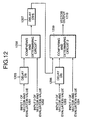
- the configuration of the vector selecting circuit 905 is shown in Fig. 12.
- the vector selecting circuit 905 comprises inputs 1201 to 1204 of the block matching evaluation values and the motion vector data from the ME circuit in Fig. 9, delays 1205 and 1206 for delaying the signal by 2t, a delay 1207 for delaying the signal by 2tH, comparing and determining circuits 1208 and 1209 and a motion vector output 1210.
- the data from the ME circuits 907, 908, 909 and 910 are input to 1201, 1202, 1203 and 1204, respectively.
- the data from the ME circuit 908 is delayed by 2t by the delay 1205 and then input to the comparing and determining circuit 1208.
- the pixel data from the ME circuit 909 is also shifted by 2t from the data from the ME circuit 909 for the same object block, the data from the ME circuit 909 is delayed by 2t by the delay 1206 and then input to the comparing and determining circuit 1209.
- the output from the comparing and determining circuit 1208 is delayed by 2tH by the delay 1207 and then input to the comparing and determining circuit 1209 in which it is compared with the data from the ME circuits 909 and 910 so that final motion vector is output from 1210.
- motion vector detection in a search area having pixels 5m by 5m can be conducted for the object block having pixels m by m.
- reference pixel memory is shown separate from the ME circuit, the invention is applicable to the configuration in which reference pixels are stored in the ME circuits.
Landscapes
- Engineering & Computer Science (AREA)
- Multimedia (AREA)
- Signal Processing (AREA)
- Compression Or Coding Systems Of Tv Signals (AREA)
Applications Claiming Priority (3)
| Application Number | Priority Date | Filing Date | Title |
|---|---|---|---|
| JP27551197A JPH11112991A (ja) | 1997-10-08 | 1997-10-08 | 動きベクトル検出装置 |
| JP275511/97 | 1997-10-08 | ||
| JP27551197 | 1997-10-08 |
Publications (3)
| Publication Number | Publication Date |
|---|---|
| EP0909098A2 true EP0909098A2 (de) | 1999-04-14 |
| EP0909098A3 EP0909098A3 (de) | 2001-08-29 |
| EP0909098B1 EP0909098B1 (de) | 2008-11-05 |
Family
ID=17556505
Family Applications (1)
| Application Number | Title | Priority Date | Filing Date |
|---|---|---|---|
| EP19980118474 Expired - Lifetime EP0909098B1 (de) | 1997-10-08 | 1998-09-30 | Vorrichtung zur Bewegungsvektordetektion |
Country Status (4)
| Country | Link |
|---|---|
| US (1) | US6356590B1 (de) |
| EP (1) | EP0909098B1 (de) |
| JP (1) | JPH11112991A (de) |
| DE (1) | DE69840191D1 (de) |
Families Citing this family (1)
| Publication number | Priority date | Publication date | Assignee | Title |
|---|---|---|---|---|
| JP4015084B2 (ja) * | 2003-08-20 | 2007-11-28 | 株式会社東芝 | 動きベクトル検出装置及び動きベクトル検出方法 |
Family Cites Families (12)
| Publication number | Priority date | Publication date | Assignee | Title |
|---|---|---|---|---|
| US4897720A (en) * | 1988-03-14 | 1990-01-30 | Bell Communications Research, Inc. | Circuit implementation of block matching algorithm |
| DE4322343C2 (de) * | 1992-07-06 | 1996-10-02 | Mitsubishi Electric Corp | Mittel zum Erfassen eines Bewegungsvektors und Verfahren zum Bestimmen eines Bewegungsvektors |
| JPH06141304A (ja) * | 1992-10-28 | 1994-05-20 | Sony Corp | 演算回路 |
| DE69327040T2 (de) * | 1993-02-22 | 2000-04-13 | Industrial Technology Research Institute, Chutung | Blockübereinstimmungsarchitektur mit mehreren Modulen |
| JP3513214B2 (ja) * | 1994-04-19 | 2004-03-31 | ソニー株式会社 | 動きベクトル検出装置 |
| JPH07288817A (ja) * | 1994-04-19 | 1995-10-31 | Sony Corp | 動きベクトル検出装置 |
| US5706059A (en) * | 1994-11-30 | 1998-01-06 | National Semiconductor Corp. | Motion estimation using a hierarchical search |
| JPH0923434A (ja) * | 1995-07-07 | 1997-01-21 | Nec Corp | 動き補償回路 |
| US5680181A (en) * | 1995-10-20 | 1997-10-21 | Nippon Steel Corporation | Method and apparatus for efficient motion vector detection |
| JPH09182080A (ja) * | 1995-12-22 | 1997-07-11 | Sony Corp | 動きベクトル検出方法および動きベクトル検出装置 |
| US5719642A (en) * | 1996-05-07 | 1998-02-17 | National Science Council Of R.O.C. | Full-search block matching motion estimation processor |
| GB2320388B (en) * | 1996-11-29 | 1999-03-31 | Sony Corp | Image processing apparatus |
-
1997
- 1997-10-08 JP JP27551197A patent/JPH11112991A/ja active Pending
-
1998
- 1998-09-30 EP EP19980118474 patent/EP0909098B1/de not_active Expired - Lifetime
- 1998-09-30 DE DE69840191T patent/DE69840191D1/de not_active Expired - Lifetime
- 1998-10-02 US US09/165,151 patent/US6356590B1/en not_active Expired - Fee Related
Also Published As
| Publication number | Publication date |
|---|---|
| EP0909098B1 (de) | 2008-11-05 |
| EP0909098A3 (de) | 2001-08-29 |
| JPH11112991A (ja) | 1999-04-23 |
| DE69840191D1 (de) | 2008-12-18 |
| US6356590B1 (en) | 2002-03-12 |
Similar Documents
| Publication | Publication Date | Title |
|---|---|---|
| EP0488795B1 (de) | Bewegungsvektorerfassungsgerät | |
| US4933759A (en) | Method of and arrangement for motion detection in an interlaced television picture obtained after film-to-television conversion | |
| US6687303B1 (en) | Motion vector detecting device | |
| US5105271A (en) | Motion picture data coding/decoding system having motion vector coding unit and decoding unit | |
| EP0765573B1 (de) | Bewegungskompensierte interpolation | |
| EP0415737B1 (de) | Bewegungsauffindungsschaltungen für Videobilder | |
| US5621481A (en) | Motion vector detecting apparatus for determining interframe, predictive error as a function of interfield predictive errors | |
| US5596370A (en) | Boundary matching motion estimation apparatus | |
| US5357287A (en) | Method of and apparatus for motion estimation of video data | |
| US5604546A (en) | Image signal processing circuit for performing motion estimation | |
| EP1086590A1 (de) | Bewegungsschätzung | |
| US5313296A (en) | Image information processor in which residual information is stored in a blank area of a field memory | |
| EP0628234A1 (de) | Bewegungskompensierte Videobildverarbeitung | |
| US5627603A (en) | Image processing apparatus utilizing a conventional signal processor to process high-definition electronic camera signals | |
| JP2005512202A (ja) | 画像データ検索 | |
| US5475446A (en) | Picture signal motion detector employing partial decimation of pixel blocks | |
| EP0909098A2 (de) | Vorrichtung zur Bewegungsvektordetektion | |
| JP3299671B2 (ja) | 画像の動き検出装置 | |
| KR100413770B1 (ko) | 완전 탐색블록 정합회로 및 완전 탐색블록 정합방법 | |
| US5612746A (en) | Block matching for picture motion estimation using offset quantized pixels | |
| EP1420595A1 (de) | Auswahl von Bewegungsvektoren in einem Bewegungsschätzer für Videodaten auf der Basis eines Referenzpunktes | |
| JP3192698B2 (ja) | 動きベクトル評価装置 | |
| US6125141A (en) | Device and method for detecting motion vectors | |
| KR100225690B1 (ko) | 상관도 연산장치, 병렬상관도 연산장치 및 상관도연산방법 | |
| US20020021366A1 (en) | Image processing apparatus and method and signal switching output device |
Legal Events
| Date | Code | Title | Description |
|---|---|---|---|
| PUAI | Public reference made under article 153(3) epc to a published international application that has entered the european phase |
Free format text: ORIGINAL CODE: 0009012 |
|
| AK | Designated contracting states |
Kind code of ref document: A2 Designated state(s): AT BE CH CY DE DK ES FI FR GB GR IE IT LI LU MC NL PT SE |
|
| AX | Request for extension of the european patent |
Free format text: AL;LT;LV;MK;RO;SI |
|
| PUAL | Search report despatched |
Free format text: ORIGINAL CODE: 0009013 |
|
| AK | Designated contracting states |
Kind code of ref document: A3 Designated state(s): AT BE CH CY DE DK ES FI FR GB GR IE IT LI LU MC NL PT SE |
|
| AX | Request for extension of the european patent |
Free format text: AL;LT;LV;MK;RO;SI |
|
| RIC1 | Information provided on ipc code assigned before grant |
Free format text: 7H 04N 7/36 A, 7H 04N 7/26 B |
|
| 17P | Request for examination filed |
Effective date: 20011029 |
|
| AKX | Designation fees paid |
Free format text: DE FR GB |
|
| 17Q | First examination report despatched |
Effective date: 20051027 |
|
| GRAP | Despatch of communication of intention to grant a patent |
Free format text: ORIGINAL CODE: EPIDOSNIGR1 |
|
| GRAS | Grant fee paid |
Free format text: ORIGINAL CODE: EPIDOSNIGR3 |
|
| GRAA | (expected) grant |
Free format text: ORIGINAL CODE: 0009210 |
|
| AK | Designated contracting states |
Kind code of ref document: B1 Designated state(s): DE FR GB |
|
| REG | Reference to a national code |
Ref country code: GB Ref legal event code: FG4D |
|
| REF | Corresponds to: |
Ref document number: 69840191 Country of ref document: DE Date of ref document: 20081218 Kind code of ref document: P |
|
| PLBE | No opposition filed within time limit |
Free format text: ORIGINAL CODE: 0009261 |
|
| STAA | Information on the status of an ep patent application or granted ep patent |
Free format text: STATUS: NO OPPOSITION FILED WITHIN TIME LIMIT |
|
| 26N | No opposition filed |
Effective date: 20090806 |
|
| PGFP | Annual fee paid to national office [announced via postgrant information from national office to epo] |
Ref country code: DE Payment date: 20130925 Year of fee payment: 16 |
|
| PGFP | Annual fee paid to national office [announced via postgrant information from national office to epo] |
Ref country code: FR Payment date: 20130910 Year of fee payment: 16 Ref country code: GB Payment date: 20130925 Year of fee payment: 16 |
|
| REG | Reference to a national code |
Ref country code: DE Ref legal event code: R119 Ref document number: 69840191 Country of ref document: DE |
|
| GBPC | Gb: european patent ceased through non-payment of renewal fee |
Effective date: 20140930 |
|
| REG | Reference to a national code |
Ref country code: DE Ref legal event code: R119 Ref document number: 69840191 Country of ref document: DE Effective date: 20150401 |
|
| REG | Reference to a national code |
Ref country code: FR Ref legal event code: ST Effective date: 20150529 |
|
| PG25 | Lapsed in a contracting state [announced via postgrant information from national office to epo] |
Ref country code: DE Free format text: LAPSE BECAUSE OF NON-PAYMENT OF DUE FEES Effective date: 20150401 Ref country code: GB Free format text: LAPSE BECAUSE OF NON-PAYMENT OF DUE FEES Effective date: 20140930 |
|
| PG25 | Lapsed in a contracting state [announced via postgrant information from national office to epo] |
Ref country code: FR Free format text: LAPSE BECAUSE OF NON-PAYMENT OF DUE FEES Effective date: 20140930 |