EP0908850B1 - Procédé de modification de forme pour système de conception assistée par ordinateur - Google Patents
Procédé de modification de forme pour système de conception assistée par ordinateur Download PDFInfo
- Publication number
- EP0908850B1 EP0908850B1 EP98402471A EP98402471A EP0908850B1 EP 0908850 B1 EP0908850 B1 EP 0908850B1 EP 98402471 A EP98402471 A EP 98402471A EP 98402471 A EP98402471 A EP 98402471A EP 0908850 B1 EP0908850 B1 EP 0908850B1
- Authority
- EP
- European Patent Office
- Prior art keywords
- zone
- deformation
- constraints
- boundaries
- modified
- Prior art date
- Legal status (The legal status is an assumption and is not a legal conclusion. Google has not performed a legal analysis and makes no representation as to the accuracy of the status listed.)
- Expired - Lifetime
Links
Images


Classifications
-
- G—PHYSICS
- G06—COMPUTING OR CALCULATING; COUNTING
- G06T—IMAGE DATA PROCESSING OR GENERATION, IN GENERAL
- G06T17/00—Three-dimensional [3D] modelling for computer graphics
- G06T17/30—Polynomial surface description
Definitions
- the subject of the present invention is a method of modification shaped, intended to allow the user of a computer-aided design system to modify a surface shape and to provide the user with a representation of the modified form.
- EP-A-0 576 218 describes a method for solving this problem.
- this process is limited to obtaining a continuity which does not exceed G 1 at the borders.
- a partial differential equation is generated which represents the surface as a physical membrane. The process is not used to modify a pre-existing shape and does not allow for higher order continuity at the borders.
- the invention aims to provide a method of modifying an existing zone while respecting a continuity G k (k being at least equal to -1) at the borders and respecting internal constraints.
- a continuity G 0 is a simple passage constraint.
- a continuity of order 1 is a constraint of continuity of tangent plane.
- a continuity of order 2 respects the normal curvatures in all directions at a point or along a curve. Higher values of k and n are possible and have no simple geometric counterpart. Sometimes a tear must be obtained between the modified area and the rest of the surface. This is designated as G -1 continuity.
- a continuity G 0 + G 1 along one side of the border requires that the "generalized" plate representing the deformation remains flat along this side after deformation.
- An external constraint G 0 at the border can be viewed, by analogy with mechanical considerations, as the requirement that there is a determined distribution of forces along the border. In the case of constraints of order G 1, the analogy with a plate returns to the application, along the border, of moments having a determined distribution, adding to the distribution of the forces. On the other hand, there is no analogy in terms of material deformation beyond a G 1 constraint. But it has been found that the increase in k results in a deeper modified form, which has greater slopes.
- the minimization calculation must be done while respecting also the continuity constraints along each of the sides of the area to be deformed. Borders can be closed or through.
- E ( ⁇ ) defines the linear energy of elastic bending of an infinite horizontal thin plate, having a zero Poisson's ratio, whose displacement field vertical is ⁇ .
- the invention also aims to provide a method for filling a hole in a surface or generating a connection zone while respecting external constraints G k , k being at least equal to 2, and internal constraints G n , n being at less than zero.
- the process described in document EP-A-0 576 218 is only capable of respecting external constraints G 0 or G 1 .
- Figures 1A and 1B show an example of application of the invention.
- Zone 10 of Figure 1A delimited by five curvilinear sides and having as many vertices, must be deformed to bring it to point A, respecting a continuity G 1 (indicated by the double arrows). This means that the planes tangent to the original "surface” along the border must remain planes tangent to both the deformed area and the rest of the original "surface” ( Figure 1B).
- the contours defining the area to be modified are projected parallel to d on a perpendicular plane ⁇ . They constitute a plane domain D ⁇ (X, Y) on which one will be able to define the law of deformation d (X, Y).
- d corresponds to ⁇ in formula (1) .
- the planar coordinates X and Y correspond to coordinates (u, v) of the initial shape of the area to be deformed.
- the curvilinear sides of the area will be defined in an approximate form by parametric polynomial (or rational) equations, chosen to ensure the required precision.
- the final modified form will be obtained by gluing ⁇ F D ⁇ and the restriction (FF D ⁇ ).
- equation (1) becomes:
- An internal constraint is introduced for example using human-computer interaction devices such as a mouse, a ball called “track ball” or any other handful of manipulation on a screen.
- the internal stress can be the fact that the deformed zone passes by a point ⁇ F D ⁇ (u 0 , v 0 ) where the direction of the initial tangent plane is preserved.
- deformation d (X, Y) is that of an initially planar and infinite plate, and not that of a plate having the original shape, in mathematical analogy.
- FIG. 3 an example has been shown. distribution of forces corresponding to a deformation particular, with a constraint of passage along the sides of the domain.
- the approach which will make it possible to determine the shape while respecting the external constraints (edge constraints) and internal (for example passage through a determined location) will be constituted by the search for the deformation corresponding to the minimum of the energy E ( ⁇ ) given by formula (1) .
- This approach can constitute an extrapolation and an adaptation of that described in the article "An Aesthetic Preserving Algorithm for Accuracy Incompatible Modelers Data Exchange” by G. Durand, A. Leutier and A. Massabo, IDMME, 1996.
- Figure 4 shows the functions to perform in setting of the process. Some of these functions are simply optional and most are already carried out by software modules available.
- a first software module 12 can be provided to verify consistency between at least the form sought, the direction deformation d, and the contours to be respected. In some case indeed, a deformation in the direction of only may not allow internal constraints to be met imposed on the model.
- the shape is processed by a module 14 which gives a projection parallel to the direction d (on the plane ⁇ in Figure 2).
- the projection on the plane ⁇ of the contours, according to the direction d, is also determined by a module 16.
- Another module 18 calculates the projection of the shape on the plane ⁇ .
- the deformations d (X, Y) are calculated by a module 20 which applies an algorithm of the "elastic infinite thin plate” type, mentioned above, respecting the constraints related. This algorithm is applied in the plane ⁇ , that is to say from a plane shape, not in space 3D; the deformations thus obtained are applied to the original "area" in the selected area.
- the parameters entered include indications of precision, taking into account continuity initial internal form to modify.
Landscapes
- Physics & Mathematics (AREA)
- Engineering & Computer Science (AREA)
- General Physics & Mathematics (AREA)
- Pure & Applied Mathematics (AREA)
- Mathematical Optimization (AREA)
- Mathematical Physics (AREA)
- Mathematical Analysis (AREA)
- Algebra (AREA)
- Computer Graphics (AREA)
- Geometry (AREA)
- Software Systems (AREA)
- Theoretical Computer Science (AREA)
- Processing Or Creating Images (AREA)
Description
- les contraintes sont celles à respecter le long de côtés de la frontière et celles, de même nature, situées en des emplacements qui sont contenus dans la zone déformée,
- l'objectif à atteindre est une "minimisation" de l'énergie généralisée de déformation.

- les figures 1A, 1B, 1C, 1D montrent des déformations possibles d'une zone d'une "surface" ;
- la figure 2 est une représentation schématique de la déformation, dans un seul plan parallèle à une direction commune de déformation, montrant les paramètres qui interviennent ;
- la figure 3 est un schéma montrant une distribution possible des forces à l'équilibre permettant le calcul de la zone déformée dans le cas de contraintes G0 le long de la frontière ;
- la figure 4 est un synoptique de principe montrant les opérations effectuées pour la détermination des déformations.

- l'identification des contours de la zone à modifier, pouvant être introduite par exemple par pointage sur un écran ou sous forme de coordonnées,
- la direction de déformation d choisie (ou la loi de direction dans le cas où les directions sont variables),
- les contraintes à respecter sur les contours,
- enfin, les caractéristiques de forme que doit respecter le modèle de déformation (contraintes internes).
Claims (6)
- Procédé de production d'une image par modification dune forme d'une zone d'une surface d'origine, suivant lequel :où(a) on définit des frontières de la zone à modifier en tant que des contraintes externes constituées par des continuités Gk le long d'au moins une fraction des frontières, k étant au moins égal à -1 ;(b) on définit des contraintes internes Gn en des points ou des courbes, à respecter par la zone une fois modifiée, n étant un entier positif ou nul ;(c) on sélectionne une loi de direction ou de déformation pour tous les points de ladite zone ;(d) on définit une déformation qui correspond à un minimum sur toute l'espace paramétrique, d'une énergie :
 R2 désigne l'espace paramétrique à deux dimensions sur lequel est projetée la frontière,▿ est l'opérateur du gradient,m est un exposant qui permet de satisfaire l'ordre de la continuité recherchée, désigne la fonction de déformation.
 - Procédé selon la revendication 1, caractérisé en ce qu'on adopte une même direction de déformation pour tous les points de la zone.
- Procédé selon l'une quelconque des revendications précédentes, caractérisé en ce que la contrainte interne est constituée par la définition d'un point et/ou d'une courbe :par lesquels doit passer le modèle, et/oupour lesquels le plan tangent et/ou la nappe osculatrice peuvent être imposés, et/oupour lesquels les courbures normales et/ou la quadrique osculatrice peuvent être imposées.
- Procédé suivant la revendication 1, suivant lequel on définit la déformation comme la déformation élastique d'une plaque plane mince infinie généralisée en équilibre, respectant les contraintes internes et externes et on génère une représentation de l'ensemble de la zone modifiée et du reste de la surface source, reliés auxdites frontières.
- Procédé selon la revendication 1, caractérisé en ce qu'on introduit en tant que contraintes internes, l'équation d'un point ou d'une courbe par laquelle doit passer la zone déformée
- Programme pour système de conception assistée par ordinateur qui, lorsqu'il est chargé dans un ordinateur, met en oeuvre un procédé de production d'une forme d'une zone d'une surface d'origine, procédé suivant lequel :où(a) on définit des frontières de la zone à modifier en tant que des contraintes externes constituées par des continuités Gk le long d'au moins une fraction des frontières, k étant au moins égal à -1 ;(b) on définit des contraintes internes Gn en des points ou des courbes à respecter par la zone une fois modifiée, n étant un entier positif ou nul ;(c) on sélectionne une loi de direction ou de déformation pour tous les points de ladite zone ;(d) on définit une déformation qui correspond à un minimum sur toute l'espace paramétrique, d'une énergie :
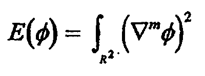 R2 désigne l'espace paramétrique à deux dimensions sur lequel est projetée la frontière,▿ est l'opérateur du gradient,m est un exposant qui permet de satisfaire l'ordre de la continuité recherchée. désigne la fonction de déformation.
Applications Claiming Priority (2)
| Application Number | Priority Date | Filing Date | Title |
|---|---|---|---|
| FR9712546A FR2769391B1 (fr) | 1997-10-08 | 1997-10-08 | Procede de modification de forme pour systeme de conception assistee par ordinateur |
| FR9712546 | 1997-10-08 |
Publications (2)
| Publication Number | Publication Date |
|---|---|
| EP0908850A1 EP0908850A1 (fr) | 1999-04-14 |
| EP0908850B1 true EP0908850B1 (fr) | 2003-06-25 |
Family
ID=9511966
Family Applications (1)
| Application Number | Title | Priority Date | Filing Date |
|---|---|---|---|
| EP98402471A Expired - Lifetime EP0908850B1 (fr) | 1997-10-08 | 1998-10-06 | Procédé de modification de forme pour système de conception assistée par ordinateur |
Country Status (4)
| Country | Link |
|---|---|
| US (1) | US6281905B1 (fr) |
| EP (1) | EP0908850B1 (fr) |
| DE (1) | DE69815782D1 (fr) |
| FR (1) | FR2769391B1 (fr) |
Families Citing this family (11)
| Publication number | Priority date | Publication date | Assignee | Title |
|---|---|---|---|---|
| US7196702B1 (en) * | 1998-07-23 | 2007-03-27 | Freedesign, Inc. | Geometric design and modeling system using control geometry |
| US8836701B1 (en) | 1998-07-23 | 2014-09-16 | Freedesign, Inc. | Surface patch techniques for computational geometry |
| US6981695B1 (en) * | 2003-10-14 | 2006-01-03 | Polaris Industries Inc. | All terrain vehicle with multiple winches |
| US7042457B2 (en) * | 2001-07-03 | 2006-05-09 | Dassault Systemes | Method and system for real-time analysis and display of curve connection quality |
| US20040113910A1 (en) * | 2002-12-12 | 2004-06-17 | Electronic Data Systems Corporation | System and method for the rebuild of curve networks in curve-based surface generation using constrained-surface fitting |
| KR101095126B1 (ko) * | 2003-04-21 | 2011-12-16 | 지멘스 프로덕트 라이프사이클 매니지먼트 소프트웨어 인크. | 곡률 연속성을 가지는 다면 매칭 시스템 및 방법 |
| US7920140B2 (en) * | 2006-03-29 | 2011-04-05 | Autodesk, Inc. | System for controlling deformation |
| US11907617B2 (en) | 2008-07-18 | 2024-02-20 | Cad-Sense Llc | Surface patch techniques for computational geometry |
| FR2962570A1 (fr) * | 2010-07-09 | 2012-01-13 | Dassault Aviat | Procede et systeme de modelisation d'une surface geometrique |
| US9536018B2 (en) | 2011-05-03 | 2017-01-03 | Fujitsu Limited | Computer-implemented method of identifying a group of perforations |
| CN105273518B (zh) * | 2014-07-24 | 2017-06-13 | 中国科学院理化技术研究所 | 具有自修复性能的耐水长效防雾抗霜聚合物涂层的制备方法 |
Family Cites Families (5)
| Publication number | Priority date | Publication date | Assignee | Title |
|---|---|---|---|---|
| US4821214A (en) * | 1986-04-17 | 1989-04-11 | Brigham Young University | Computer graphics method for changing the shape of a geometric model using free-form deformation |
| JP2762000B2 (ja) * | 1992-06-25 | 1998-06-04 | 株式会社日立製作所 | 曲面生成方法および曲面生成装置 |
| US5636338A (en) * | 1993-01-29 | 1997-06-03 | Silicon Graphics, Inc. | Method for designing curved shapes for use by a computer |
| US5619625A (en) * | 1993-05-28 | 1997-04-08 | Ricoh Company, Ltd. | Method for interpolating smooth free-form surfaces into curve mesh including composite curves |
| US5731819A (en) * | 1995-07-18 | 1998-03-24 | Softimage | Deformation of a graphic object to emphasize effects of motion |
-
1997
- 1997-10-08 FR FR9712546A patent/FR2769391B1/fr not_active Expired - Fee Related
-
1998
- 1998-10-06 EP EP98402471A patent/EP0908850B1/fr not_active Expired - Lifetime
- 1998-10-06 DE DE69815782T patent/DE69815782D1/de not_active Expired - Lifetime
- 1998-10-07 US US09/167,666 patent/US6281905B1/en not_active Expired - Fee Related
Also Published As
| Publication number | Publication date |
|---|---|
| EP0908850A1 (fr) | 1999-04-14 |
| DE69815782D1 (de) | 2003-07-31 |
| FR2769391A1 (fr) | 1999-04-09 |
| FR2769391B1 (fr) | 2000-11-10 |
| US6281905B1 (en) | 2001-08-28 |
Similar Documents
| Publication | Publication Date | Title |
|---|---|---|
| EP0908850A1 (fr) | Procédé de modification de forme pour système de conception assistée par ordinateur | |
| EP2715662B1 (fr) | Procede de localisation d'une camera et de reconstruction 3d dans un environnement partiellement connu | |
| EP1088279B1 (fr) | Procede de recherche d'images, fonde sur une indexation invariante des images | |
| WO2017021644A1 (fr) | Traitement de donnees geometriques, avec approximation isotopique dans un volume de tolerance | |
| EP1231568A1 (fr) | Dispositif de simulation de déformations de matériaux, notamment de tissus corporels mous | |
| EP2212733B1 (fr) | Procédé et dispositif de reconstruction du volume d'un objet à partir d'une séquence d'images de coupes dudit objet | |
| FR2999325A1 (fr) | Procede iteratif de determination d'une image en deux dimensions ou trois dimensions a partir de signaux issus de tomographie par rayons x | |
| EP2082374A1 (fr) | Procede et dispositifs d'aide a la modelisation d'objets 3d | |
| EP2027968B1 (fr) | Procédé de détermination de paramètres de monturisation d'une lentille ophtalmique | |
| WO2010029268A1 (fr) | Procede et dispositif de realisation d'un modele par elements finis | |
| EP4193334A1 (fr) | Procede de caracterisation d'une structure fibreuse tissee | |
| EP3381013B1 (fr) | Procédé de contrôle non destructif d'une pièce pour aéronautique | |
| EP2359339A1 (fr) | Procédé de conception assistée par ordinateur pour créer une surface dans un système complexe | |
| Bouchara et al. | Immersive sonification of protein surface | |
| EP3785083B1 (fr) | Procede de traitement d'un hologramme, dispositif, systeme de restitution holographique et programme d'ordinateur associes | |
| EP1121665B1 (fr) | Procede de codage d'un maillage source, avec optimisation de la position d'un sommet resultant d'une fusion d'arete, et applications correspondantes | |
| EP2405373A2 (fr) | Procédé et système de modélisation d'une surface géométrique | |
| EP3545426A1 (fr) | Procede de simulation rapide d'un systeme optique | |
| WO2009101327A2 (fr) | Procede et dispositif de simulation de contact par images a plan de profondeur | |
| EP2904587A2 (fr) | Procédé de traitement de données définissant un élément dans un espace e de dimensions d, programme d'ordinateur associé | |
| Bonhomme | Variational methods applied to discrete and evolutionary brittle damage models | |
| Tavares et al. | A two-dimensional conservative front-tracking method for multi-scale multiphase flows | |
| EP3884332B1 (fr) | Procede de creation d'un composant optique pour générer, a partir d'une source d'eclairage donnée, un eclairage en champ proche donne | |
| Fang | Geometric modeling of man-made objects at different level of details | |
| FR3156563A1 (fr) | Procédé et dispositif de modélisation d’un objet réel |
Legal Events
| Date | Code | Title | Description |
|---|---|---|---|
| PUAI | Public reference made under article 153(3) epc to a published international application that has entered the european phase |
Free format text: ORIGINAL CODE: 0009012 |
|
| AK | Designated contracting states |
Kind code of ref document: A1 Designated state(s): DE ES GB IT NL |
|
| AX | Request for extension of the european patent |
Free format text: AL;LT;LV;MK;RO;SI |
|
| 17P | Request for examination filed |
Effective date: 19990617 |
|
| AKX | Designation fees paid |
Free format text: DE ES GB IT NL |
|
| 17Q | First examination report despatched |
Effective date: 20020417 |
|
| RAP1 | Party data changed (applicant data changed or rights of an application transferred) |
Owner name: EADS MATRA DATAVISION |
|
| GRAH | Despatch of communication of intention to grant a patent |
Free format text: ORIGINAL CODE: EPIDOS IGRA |
|
| GRAH | Despatch of communication of intention to grant a patent |
Free format text: ORIGINAL CODE: EPIDOS IGRA |
|
| RAP1 | Party data changed (applicant data changed or rights of an application transferred) |
Owner name: OPEN CASCADE |
|
| GRAA | (expected) grant |
Free format text: ORIGINAL CODE: 0009210 |
|
| AK | Designated contracting states |
Designated state(s): DE ES GB IT NL |
|
| PG25 | Lapsed in a contracting state [announced via postgrant information from national office to epo] |
Ref country code: NL Free format text: LAPSE BECAUSE OF FAILURE TO SUBMIT A TRANSLATION OF THE DESCRIPTION OR TO PAY THE FEE WITHIN THE PRESCRIBED TIME-LIMIT Effective date: 20030625 Ref country code: IT Free format text: LAPSE BECAUSE OF FAILURE TO SUBMIT A TRANSLATION OF THE DESCRIPTION OR TO PAY THE FEE WITHIN THE PRESCRIBED TIME-LIMIT;WARNING: LAPSES OF ITALIAN PATENTS WITH EFFECTIVE DATE BEFORE 2007 MAY HAVE OCCURRED AT ANY TIME BEFORE 2007. THE CORRECT EFFECTIVE DATE MAY BE DIFFERENT FROM THE ONE RECORDED. Effective date: 20030625 Ref country code: GB Free format text: LAPSE BECAUSE OF FAILURE TO SUBMIT A TRANSLATION OF THE DESCRIPTION OR TO PAY THE FEE WITHIN THE PRESCRIBED TIME-LIMIT Effective date: 20030625 |
|
| REG | Reference to a national code |
Ref country code: GB Ref legal event code: FG4D Free format text: NOT ENGLISH |
|
| REF | Corresponds to: |
Ref document number: 69815782 Country of ref document: DE Date of ref document: 20030731 Kind code of ref document: P |
|
| PG25 | Lapsed in a contracting state [announced via postgrant information from national office to epo] |
Ref country code: DE Free format text: LAPSE BECAUSE OF FAILURE TO SUBMIT A TRANSLATION OF THE DESCRIPTION OR TO PAY THE FEE WITHIN THE PRESCRIBED TIME-LIMIT Effective date: 20030926 |
|
| NLV1 | Nl: lapsed or annulled due to failure to fulfill the requirements of art. 29p and 29m of the patents act | ||
| PG25 | Lapsed in a contracting state [announced via postgrant information from national office to epo] |
Ref country code: ES Free format text: LAPSE BECAUSE OF FAILURE TO SUBMIT A TRANSLATION OF THE DESCRIPTION OR TO PAY THE FEE WITHIN THE PRESCRIBED TIME-LIMIT Effective date: 20031222 |
|
| GBV | Gb: ep patent (uk) treated as always having been void in accordance with gb section 77(7)/1977 [no translation filed] |
Effective date: 20030625 |
|
| PLBE | No opposition filed within time limit |
Free format text: ORIGINAL CODE: 0009261 |
|
| STAA | Information on the status of an ep patent application or granted ep patent |
Free format text: STATUS: NO OPPOSITION FILED WITHIN TIME LIMIT |
|
| 26N | No opposition filed |
Effective date: 20040326 |
|
| REG | Reference to a national code |
Ref country code: HK Ref legal event code: WD Ref document number: 1020097 Country of ref document: HK |