EP0908613B1 - Engine exhaust gas control system having NOx catalyst - Google Patents
Engine exhaust gas control system having NOx catalyst Download PDFInfo
- Publication number
- EP0908613B1 EP0908613B1 EP98119231A EP98119231A EP0908613B1 EP 0908613 B1 EP0908613 B1 EP 0908613B1 EP 98119231 A EP98119231 A EP 98119231A EP 98119231 A EP98119231 A EP 98119231A EP 0908613 B1 EP0908613 B1 EP 0908613B1
- Authority
- EP
- European Patent Office
- Prior art keywords
- time
- rich
- nox
- air
- fuel ratio
- Prior art date
- Legal status (The legal status is an assumption and is not a legal conclusion. Google has not performed a legal analysis and makes no representation as to the accuracy of the status listed.)
- Expired - Lifetime
Links
Images


Classifications
-
- F—MECHANICAL ENGINEERING; LIGHTING; HEATING; WEAPONS; BLASTING
- F01—MACHINES OR ENGINES IN GENERAL; ENGINE PLANTS IN GENERAL; STEAM ENGINES
- F01N—GAS-FLOW SILENCERS OR EXHAUST APPARATUS FOR MACHINES OR ENGINES IN GENERAL; GAS-FLOW SILENCERS OR EXHAUST APPARATUS FOR INTERNAL-COMBUSTION ENGINES
- F01N3/00—Exhaust or silencing apparatus having means for purifying, rendering innocuous, or otherwise treating exhaust
- F01N3/08—Exhaust or silencing apparatus having means for purifying, rendering innocuous, or otherwise treating exhaust for rendering innocuous
- F01N3/0807—Exhaust or silencing apparatus having means for purifying, rendering innocuous, or otherwise treating exhaust for rendering innocuous by using absorbents or adsorbents
- F01N3/0828—Exhaust or silencing apparatus having means for purifying, rendering innocuous, or otherwise treating exhaust for rendering innocuous by using absorbents or adsorbents characterised by the absorbed or adsorbed substances
- F01N3/0842—Nitrogen oxides
-
- F—MECHANICAL ENGINEERING; LIGHTING; HEATING; WEAPONS; BLASTING
- F02—COMBUSTION ENGINES; HOT-GAS OR COMBUSTION-PRODUCT ENGINE PLANTS
- F02D—CONTROLLING COMBUSTION ENGINES
- F02D41/00—Electrical control of supply of combustible mixture or its constituents
- F02D41/02—Circuit arrangements for generating control signals
- F02D41/021—Introducing corrections for particular conditions exterior to the engine
- F02D41/0235—Introducing corrections for particular conditions exterior to the engine in relation with the state of the exhaust gas treating apparatus
- F02D41/027—Introducing corrections for particular conditions exterior to the engine in relation with the state of the exhaust gas treating apparatus to purge or regenerate the exhaust gas treating apparatus
- F02D41/0275—Introducing corrections for particular conditions exterior to the engine in relation with the state of the exhaust gas treating apparatus to purge or regenerate the exhaust gas treating apparatus the exhaust gas treating apparatus being a NOx trap or adsorbent
-
- F—MECHANICAL ENGINEERING; LIGHTING; HEATING; WEAPONS; BLASTING
- F01—MACHINES OR ENGINES IN GENERAL; ENGINE PLANTS IN GENERAL; STEAM ENGINES
- F01N—GAS-FLOW SILENCERS OR EXHAUST APPARATUS FOR MACHINES OR ENGINES IN GENERAL; GAS-FLOW SILENCERS OR EXHAUST APPARATUS FOR INTERNAL-COMBUSTION ENGINES
- F01N13/00—Exhaust or silencing apparatus characterised by constructional features
- F01N13/009—Exhaust or silencing apparatus characterised by constructional features having two or more separate purifying devices arranged in series
-
- F—MECHANICAL ENGINEERING; LIGHTING; HEATING; WEAPONS; BLASTING
- F01—MACHINES OR ENGINES IN GENERAL; ENGINE PLANTS IN GENERAL; STEAM ENGINES
- F01N—GAS-FLOW SILENCERS OR EXHAUST APPARATUS FOR MACHINES OR ENGINES IN GENERAL; GAS-FLOW SILENCERS OR EXHAUST APPARATUS FOR INTERNAL-COMBUSTION ENGINES
- F01N3/00—Exhaust or silencing apparatus having means for purifying, rendering innocuous, or otherwise treating exhaust
- F01N3/08—Exhaust or silencing apparatus having means for purifying, rendering innocuous, or otherwise treating exhaust for rendering innocuous
- F01N3/10—Exhaust or silencing apparatus having means for purifying, rendering innocuous, or otherwise treating exhaust for rendering innocuous by thermal or catalytic conversion of noxious components of exhaust
- F01N3/105—General auxiliary catalysts, e.g. upstream or downstream of the main catalyst
-
- F—MECHANICAL ENGINEERING; LIGHTING; HEATING; WEAPONS; BLASTING
- F02—COMBUSTION ENGINES; HOT-GAS OR COMBUSTION-PRODUCT ENGINE PLANTS
- F02D—CONTROLLING COMBUSTION ENGINES
- F02D41/00—Electrical control of supply of combustible mixture or its constituents
- F02D41/02—Circuit arrangements for generating control signals
- F02D41/021—Introducing corrections for particular conditions exterior to the engine
- F02D41/0235—Introducing corrections for particular conditions exterior to the engine in relation with the state of the exhaust gas treating apparatus
- F02D41/027—Introducing corrections for particular conditions exterior to the engine in relation with the state of the exhaust gas treating apparatus to purge or regenerate the exhaust gas treating apparatus
-
- F—MECHANICAL ENGINEERING; LIGHTING; HEATING; WEAPONS; BLASTING
- F02—COMBUSTION ENGINES; HOT-GAS OR COMBUSTION-PRODUCT ENGINE PLANTS
- F02D—CONTROLLING COMBUSTION ENGINES
- F02D41/00—Electrical control of supply of combustible mixture or its constituents
- F02D41/02—Circuit arrangements for generating control signals
- F02D41/14—Introducing closed-loop corrections
- F02D41/1438—Introducing closed-loop corrections using means for determining characteristics of the combustion gases; Sensors therefor
- F02D41/1444—Introducing closed-loop corrections using means for determining characteristics of the combustion gases; Sensors therefor characterised by the characteristics of the combustion gases
- F02D41/146—Introducing closed-loop corrections using means for determining characteristics of the combustion gases; Sensors therefor characterised by the characteristics of the combustion gases the characteristics being an NOx content or concentration
- F02D41/1463—Introducing closed-loop corrections using means for determining characteristics of the combustion gases; Sensors therefor characterised by the characteristics of the combustion gases the characteristics being an NOx content or concentration of the exhaust gases downstream of exhaust gas treatment apparatus
-
- F—MECHANICAL ENGINEERING; LIGHTING; HEATING; WEAPONS; BLASTING
- F02—COMBUSTION ENGINES; HOT-GAS OR COMBUSTION-PRODUCT ENGINE PLANTS
- F02D—CONTROLLING COMBUSTION ENGINES
- F02D41/00—Electrical control of supply of combustible mixture or its constituents
- F02D41/02—Circuit arrangements for generating control signals
- F02D41/14—Introducing closed-loop corrections
- F02D41/1438—Introducing closed-loop corrections using means for determining characteristics of the combustion gases; Sensors therefor
- F02D41/1473—Introducing closed-loop corrections using means for determining characteristics of the combustion gases; Sensors therefor characterised by the regulation method
- F02D41/1475—Regulating the air fuel ratio at a value other than stoichiometry
-
- B—PERFORMING OPERATIONS; TRANSPORTING
- B01—PHYSICAL OR CHEMICAL PROCESSES OR APPARATUS IN GENERAL
- B01D—SEPARATION
- B01D53/00—Separation of gases or vapours; Recovering vapours of volatile solvents from gases; Chemical or biological purification of waste gases, e.g. engine exhaust gases, smoke, fumes, flue gases, aerosols
- B01D53/34—Chemical or biological purification of waste gases
- B01D53/92—Chemical or biological purification of waste gases of engine exhaust gases
- B01D53/94—Chemical or biological purification of waste gases of engine exhaust gases by catalytic processes
-
- F—MECHANICAL ENGINEERING; LIGHTING; HEATING; WEAPONS; BLASTING
- F01—MACHINES OR ENGINES IN GENERAL; ENGINE PLANTS IN GENERAL; STEAM ENGINES
- F01N—GAS-FLOW SILENCERS OR EXHAUST APPARATUS FOR MACHINES OR ENGINES IN GENERAL; GAS-FLOW SILENCERS OR EXHAUST APPARATUS FOR INTERNAL-COMBUSTION ENGINES
- F01N2250/00—Combinations of different methods of purification
- F01N2250/12—Combinations of different methods of purification absorption or adsorption, and catalytic conversion
-
- F—MECHANICAL ENGINEERING; LIGHTING; HEATING; WEAPONS; BLASTING
- F01—MACHINES OR ENGINES IN GENERAL; ENGINE PLANTS IN GENERAL; STEAM ENGINES
- F01N—GAS-FLOW SILENCERS OR EXHAUST APPARATUS FOR MACHINES OR ENGINES IN GENERAL; GAS-FLOW SILENCERS OR EXHAUST APPARATUS FOR INTERNAL-COMBUSTION ENGINES
- F01N2370/00—Selection of materials for exhaust purification
- F01N2370/02—Selection of materials for exhaust purification used in catalytic reactors
-
- F—MECHANICAL ENGINEERING; LIGHTING; HEATING; WEAPONS; BLASTING
- F01—MACHINES OR ENGINES IN GENERAL; ENGINE PLANTS IN GENERAL; STEAM ENGINES
- F01N—GAS-FLOW SILENCERS OR EXHAUST APPARATUS FOR MACHINES OR ENGINES IN GENERAL; GAS-FLOW SILENCERS OR EXHAUST APPARATUS FOR INTERNAL-COMBUSTION ENGINES
- F01N2570/00—Exhaust treating apparatus eliminating, absorbing or adsorbing specific elements or compounds
- F01N2570/14—Nitrogen oxides
-
- F—MECHANICAL ENGINEERING; LIGHTING; HEATING; WEAPONS; BLASTING
- F01—MACHINES OR ENGINES IN GENERAL; ENGINE PLANTS IN GENERAL; STEAM ENGINES
- F01N—GAS-FLOW SILENCERS OR EXHAUST APPARATUS FOR MACHINES OR ENGINES IN GENERAL; GAS-FLOW SILENCERS OR EXHAUST APPARATUS FOR INTERNAL-COMBUSTION ENGINES
- F01N3/00—Exhaust or silencing apparatus having means for purifying, rendering innocuous, or otherwise treating exhaust
- F01N3/08—Exhaust or silencing apparatus having means for purifying, rendering innocuous, or otherwise treating exhaust for rendering innocuous
- F01N3/0807—Exhaust or silencing apparatus having means for purifying, rendering innocuous, or otherwise treating exhaust for rendering innocuous by using absorbents or adsorbents
- F01N3/0814—Exhaust or silencing apparatus having means for purifying, rendering innocuous, or otherwise treating exhaust for rendering innocuous by using absorbents or adsorbents combined with catalytic converters, e.g. NOx absorption/storage reduction catalysts
-
- F—MECHANICAL ENGINEERING; LIGHTING; HEATING; WEAPONS; BLASTING
- F02—COMBUSTION ENGINES; HOT-GAS OR COMBUSTION-PRODUCT ENGINE PLANTS
- F02D—CONTROLLING COMBUSTION ENGINES
- F02D41/00—Electrical control of supply of combustible mixture or its constituents
- F02D41/02—Circuit arrangements for generating control signals
- F02D41/14—Introducing closed-loop corrections
- F02D41/1401—Introducing closed-loop corrections characterised by the control or regulation method
- F02D41/1402—Adaptive control
-
- F—MECHANICAL ENGINEERING; LIGHTING; HEATING; WEAPONS; BLASTING
- F02—COMBUSTION ENGINES; HOT-GAS OR COMBUSTION-PRODUCT ENGINE PLANTS
- F02D—CONTROLLING COMBUSTION ENGINES
- F02D41/00—Electrical control of supply of combustible mixture or its constituents
- F02D41/02—Circuit arrangements for generating control signals
- F02D41/14—Introducing closed-loop corrections
- F02D41/1438—Introducing closed-loop corrections using means for determining characteristics of the combustion gases; Sensors therefor
- F02D41/1444—Introducing closed-loop corrections using means for determining characteristics of the combustion gases; Sensors therefor characterised by the characteristics of the combustion gases
- F02D41/1454—Introducing closed-loop corrections using means for determining characteristics of the combustion gases; Sensors therefor characterised by the characteristics of the combustion gases the characteristics being an oxygen content or concentration or the air-fuel ratio
- F02D41/1456—Introducing closed-loop corrections using means for determining characteristics of the combustion gases; Sensors therefor characterised by the characteristics of the combustion gases the characteristics being an oxygen content or concentration or the air-fuel ratio with sensor output signal being linear or quasi-linear with the concentration of oxygen
Definitions
- the present invention relates to an engine exhaust gas control system for performing a lean mixture combustion in an air-fuel ratio lean zone and to an engine exhaust control system having an NOx occluding and reducing catalyst for purifying nitrogen oxides (NOx) in exhaust gas produced at the time of the lean mixture combustion.
- NOx nitrogen oxides
- JP patent No. 2600492 discloses an NOx absorbent (NOx occluding and reducing catalyst) for absorbing NOx when the air-fuel ratio of the exhaust gas is in the lean state and releasing the absorbed NOx when the concentration of oxygen in the exhaust gas is reduced, that is, when the air-fuel ratio is in the rich state.
- NOx absorbent NOx occluding and reducing catalyst
- EP-A-0 733 787 A teaches to set a rich time (rich mixture combustion period) of the air-fuel mixture and a cycle at which the air-fuel ratio of the air-fuel mixture are made rich in accordance with a deterioration state or a maximum possible amount of absorption of the NOx catalyst.
- the air-fuel ratio of the mixture near the NOx catalyst does not immediately change to the rich side. Consequently, it is necessary to set the rich time rather long to continue the rich mixture combustion for a time including a time required for a gas condition in an exhaust pipe to shift from the lean state to the rich state. In such a case, when the rich mixture combustion is continued, the fuel injection amount is increased excessively, increasing fuel consumption. At the time of the rich mixture combustion, the engine generating torque is larger than that at the time of the lean mixture combustion. Consequently, when the rich time continues long, fluctuation in engine crankshaft rotation becomes large.
- a lean air-fuel mixture is supplied to an internal combustion engine, so that NOx in exhaust gas is occluded by an NOx catalyst for occluding and reducing NOx.
- a rich air-fuel mixture is supplied only temporarily to the engine, so that the occluded NOx is released from the NOx catalyst.
- a rich time for a rich mixture combustion is controlled variably to a minimum. The rich time is set in accordance with an NOx purification state of the NOx catalyst. That is, the rich time is shortened at every predetermined interval until the NOx purification state detected by a sensor indicates a limit of the rich time.
- an internal combustion engine 1 is a four-cylinder four-cycle spark ignition type.
- An intake pipe 2 and an exhaust pipe 3 are connected to the engine 1.
- the intake pipe 2 is provided with a throttle valve 5 which operates interlockingly with an accelerator pedal 4.
- the opening angle of the throttle valve 5 is detected by a throttle valve sensor 6.
- An intake pressure sensor 8 is arranged in a surge tank 7 of the intake pipe 2.
- a piston 10 is arranged in a cylinder 9 serving as a cylinder of the engine 1 and the piston 10 is connected to a crankshaft (not shown) via a connecting rod 11.
- a combustion chamber 13 defined by the cylinder 9 and a cylinder head 12 is formed above the piston 10. The combustion chamber 13 is communicated with the intake pipe 2 and the exhaust pipe 3 via an intake valve 14 and an exhaust valve 15.
- the exhaust pipe 3 is provided with an A/F sensor 16 constructed by a limit-current type air-fuel ratio sensor for outputting a linear air-fuel ratio signal in a wide zone in proportion to the concentration of oxygen in the exhaust gas (or the concentration of carbon monoxide and the like in unburned gas).
- an NOx catalyst 19 having the function of purifying NOx.
- the NOx catalyst 19 is known as an NOx occlusion and reduction type catalyst, which occludes NOx in the state of a lean air-fuel ratio and reduces and releases the occluded NOx in the form of CO and HC in the state of the rich air-fuel ratio.
- An intake port 17 of the engine 1 is provided with an electromagnetically driven injector 18.
- a fuel gasoline
- a fuel tank not shown
- MPI multipoint injection
- injectors 18 for respective branch pipes of an intake manifold is constructed.
- a fresh air supplied from the upstream of the intake pipe and a fuel injected by the injector 18 are mixed in the intake port 17.
- the mixture flows into the combustion chamber 13 (cylinder 9) with the opening operation of the intake valve 14.
- a spark plug 27 arranged in the cylinder head 12 ignites by a high voltage for ignition from an igniter 28.
- a distributor 20 for distributing the high voltage for ignition to the spark plugs 27 of the cylinders is connected to the igniter 28.
- a reference position sensor 21 for generating a pulse signal every 720 ° CA in accordance with the rotating state of the crankshaft and a rotational angle sensor 22 for generating a pulse signal every smaller crank angle (for example, every 30 ° CA) are arranged.
- a coolant temperature sensor 23 for sensing the temperature of coolant is arranged in the cylinder 9 (water jacket).
- An ECU 30 is mainly constructed by a known microcomputer and has a CPU 31, a ROM 32, a RAM 33, a backup RAM 34, an A/D converter 35, an input/output interface (I/O) 36, and the like. Detection signals of the throttle opening angle sensor 6, the intake pressure sensor 8, the A/F sensor 16, and the water temperature sensor 23 are supplied to the A/D converter 35 and are A/D converted. After that, the resultant signals are fetched by the CPU 31 via a bus 37. The pulse signals of the reference position sensor 21 and the rotational angle sensor 22 are fetched by the CPU 31 via the input/output, interface 36 and the bus 37.
- the CPU 31 detects the engine operating states such as a throttle opening angle TH, an intake pressure PM, an air-fuel ratio (A/F), a coolant temperature Tw, a reference crank position (G signal), and an engine speed Ne.
- the CPU 31 calculates control signals of the fuel injection amount, ignition timing, and the like on the basis of the engine operating state and outputs the control signals to the injector 18 and the igniter 28.
- the ECU 30 is programmed to execute various routines to control the exhaust gas.
- a fuel injection control routine is executed by the CPU 31 at every fuel injection (every 180° CA in the example) of each cylinder.
- step 101 the CPU 31 reads a sensor detection result (engine speed Ne, intake pressure PM, coolant temperature Tw, and the like) showing the engine operating state.
- step 102 the CPU 31 calculates a basic injection amount TP according to the engine speed Ne and the intake pressure PM at each time by using a basic injection map preliminarily stored in the ROM 32.
- the CPU 31 discriminates whether known air-fuel ratio F/B conditions are satisfied or not in step 103.
- the air-fuel ratio F/B conditions include a condition that the coolant temperature Tw is equal to or higher than a predetermined temperature, a condition that the rotation speed is not high and the load is not high, a condition that the A/F sensor 16 is in an active state, and the like.
- step 103 When step 103 is positively discriminated (when the F/B conditions are satisfied), the CPU 31 advances to step 200 and executes a process for setting a target air-fuel ratio ⁇ TG.
- the process for setting the target air-fuel ratio ⁇ TG is performed in accordance with the routine of Fig. 3 which will be described hereinlater.
- step 105 the CPU 31 sets the air-fuel ratio correction coefficient FAF on the basis of the deviation of the actual air-fuel ratio ⁇ (sensor measurement value) at each time from the target air-fuel ratio ⁇ TG.
- the air-fuel ratio F/B control based on the advanced control theory is executed.
- the air-fuel ratio correction coefficient FAF to make the detection result of the A/F sensor 16 coincide with the target air-fuel ratio at the time of the F/B control is calculated by using the following (1) and (2) equations in the known manner.
- ⁇ denotes an air-fuel ratio conversion value of the limit current by the A/F sensor 16
- K1 to Kn+1 denote F/B constants
- ZI shows an integration term
- Ka shows an integration constant.
- the suffixes 1 to n+1 are variables each showing the number of controls from the sampling start.
- step 106 the CPU 31 calculates a final fuel injection amount TAU from the basic injection amount Tp, the air-fuel ratio correction coefficient FAF, and other correction coefficients FALL (various correction coefficients of coolant temperature, air-conditioner load, and the like) by using the following equation (3).
- TAU Tp ⁇ FAF ⁇ FALL
- the CPU 31 outputs a control signal corresponding to the TAU value to the injector 18 and finishes the routine once.
- a ⁇ TG setting routine corresponding to the process of step 200 is shown in Fig. 3 .
- the target air-fuel ratio ⁇ TG is properly set in such a manner that the rich mixture combustion is performed temporarily during the execution of the lean mixture combustion. That is, in the example, a lean time LT and a rich time RT are set so as to be at a predetermined time ratio on the basis of the value of a period counter PC which counts every fuel injection and the lean mixture combustion and the rich mixture combustion are alternately executed in accordance with the times LT and RT.
- the lean time LT and the rich time RT correspond to the number of fuel injection times at the lean air-fuel ratio and the number of fuel injection times at the rich air-fuel ratio, respectively.
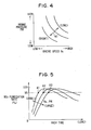
- the rich time RT is derived by retrieving a map data based on the relation of Fig. 4 .
- the relation of Fig. 4 is set so as to realize the shortest rich time within a range in which a desired NOx purification rate by the NOx catalyst 19 is obtained.
- the characteristic of the NOx purification rate with the rich time has the relation of Fig. 5 .
- the characteristic of the NOx purification rate changes depending on the engine operating state (engine speed Ne and intake pressure PM).
- the larger Ne and PM are the more the characteristic of the NOx purification rate moves to the right side in the figure.
- the smaller Ne and PM the characteristic of the NOx purification rate moves to the left side of the drawing.
- the optimum rich time is obtained from A1, A2, and A3 in Fig. 5 in accordance with the states of Ne and PM (where A1 ⁇ A2 ⁇ A3).
- the lean time LT is obtained from the rich time RT and a predetermined coefficient ⁇ as follows.
- LT RT ⁇ ⁇ It is sufficient to set the coefficient ⁇ to a fixed value of approximately 100.
- the coefficient ⁇ can be also variably set in accordance with the engine operating state such as the engine speed Ne and the intake pressure PM.
- the CPU 31 increases the period counter PC by "1" in step 203. Then the CPU 31 discriminates whether the PC value reaches a value corresponding to the set lean time LT or not in step 204. When PC ⁇ LT and step 204 is discriminated negatively, the CPU 31 advances to step 205 and sets the target air-fuel ratio ⁇ TG as a lean control value on the basis of the engine speed Ne and the intake pressure PM at each time. After setting the ⁇ TG value, the CPU 31 is returned to the original routine of Fig. 2 .
- the ⁇ TG value is set near the stoichiometric ratio.
- the ⁇ TG value set in step 205 is used for the calculation of the FAF value in step 105 in Fig. 2 and the air-fuel ratio is controlled to the lean side by the FAF value.
- the CPU 31 advances to step 206 and the target air-fuel ratio ⁇ TG is set as a rich control value.
- the ⁇ TG value can be set to a fixed value in the rich zone or variably set by retrieving the map data on the basis of the engine speed Ne and the intake pressure PM.
- the ⁇ TG value is set so that the higher the engine speed Ne is or the higher the intake pressure PM is, the degree of richness becomes higher.
- the CPU 31 discriminates whether or not the PC value reaches a value corresponding to the sum "LT + RT" of the lean time LT and the rich time RT which have been set in step 207.
- the CPU 31 returns to the original routine of Fig. 2 .
- the ⁇ TG value set in step 206 is used for the calculation of the FAF value in step 105 in Fig. 2 and the air-fuel ratio is controlled to be on the rich side by the FAF value.
- step 207 is discriminated positively, the CPU 31 clears the period counter to "0" in step 208 and returns to the original routine of Fig. 2 .
- step 201 is discriminated as YES in the next processing and the lean time LT and the rich time RT are newly set.
- the lean control and the rich control of the air-fuel ratio are executed again on the basis of the lean time LT and the rich time RT.
- This embodiment of the invention is characterized in that the rich time is learned one by one while monitoring the NOx purification state by the NOx catalyst 19 in order to optimally shorten the rich time.
- an NOx sensor 41 serving as catalyst state detector is provided on the downstream side of the NOx catalyst 19 and an output of the sensor 41 is fetched by the ECU 30.
- the ECU 30 learns to gradually shorten the rich time while monitoring the output of the NOx sensor.
- the rich time at that time is regarded as the minimum and is stored into the backup RAM 34 in the ECU 30.
- the sensor 41 generates a current signal corresponding to the NOx concentration by using an oxygen ion conductive solid electrolyte substrate made of stabilized zirconia or the like.
- the engine operating zone from 1 to n is set according to the engine speed Ne and the intake pressure PM and the learning completion flag Fi is provided for every operating zone.
- the flag Fi is initialized to "0" in the beginning of activation of the routine.
- step 302 the CPU 31 discriminates whether or not a predetermined engine operating state is continued for 10 or more seconds.
- step 303 whether the lean/rich switching is executed or not, that is, whether the stoichiometric operation is executed or not in the cases of low-temperature start of the engine 1, high load operation, and the like.
- step 304 the CPU 31 clears the rich time learning counter RTLC for measuring time intervals of the rich time learning time to "0" and finishes the routine once.
- step 305 the CPU 31 increases RTLC by "1".
- step 306 the CPU 31 discriminates whether the value of the RTLC at that time reaches a value corresponding to a predetermined time (60 seconds in the embodiment) or not. If RTLC ⁇ 60 seconds, the CPU 31 finishes the routine as it is. If RTLC ⁇ 60 seconds, the CPU 31 advances to the next step 307.
- the time of "60 seconds" corresponds to a time required for rich time learning (learning period).
- the CPU 31 regards that the rich time can be shortened more and shortens the rich time (the number of rich injection times) only by one injection in step 308.
- the initial value of the rich time is set to about 10 injections.
- the CPU 31 clears RTLC to "0" in the following step 309 and finishes the routine. In this manner, in the state where the discrimination result of step 307 is YES, the rich time is gradually shortened.
- the CPU 31 regards that the desired NOx purification rate cannot be assured with the present rich time and increases the rich time (the number of rich injections) only by one injection in step 310.
- the CPU 31 stores the rich time at that time into the backup RAM 34 in the following step 311.
- the rich time learned is stored for every engine operation state (every zone from 1 to n) at each time.
- the learned value of the rich time stored in the backup RAM 34 is stored and held even if the power source is disconnected.
- each of the periods defined by times t1 to t4 shows a rich time learning period (60 seconds in the embodiment).
- the output of the NOx sensor (average value in the learning period) is below the predetermined value (20 ppm). Consequently, the rich time is shortened only by one injection (step 308 in Fig. 10 ).
- the output (average value in the term from time t3 to time t4) of the NOx sensor exceeds the predetermined value (20 ppm).
- the rich time of one injection is therefore added and the resultant rich time is stored as a learned value into the memory (steps 310 and 311 in Fig. 10 ).
- "1" is set to the learning completion flag Fi (step 312 in Fig. 10 ).
Landscapes
- Engineering & Computer Science (AREA)
- Chemical & Material Sciences (AREA)
- Combustion & Propulsion (AREA)
- Mechanical Engineering (AREA)
- General Engineering & Computer Science (AREA)
- Materials Engineering (AREA)
- Health & Medical Sciences (AREA)
- Chemical Kinetics & Catalysis (AREA)
- Toxicology (AREA)
- Exhaust Gas After Treatment (AREA)
- Electrical Control Of Air Or Fuel Supplied To Internal-Combustion Engine (AREA)
Description
- The present invention relates to an engine exhaust gas control system for performing a lean mixture combustion in an air-fuel ratio lean zone and to an engine exhaust control system having an NOx occluding and reducing catalyst for purifying nitrogen oxides (NOx) in exhaust gas produced at the time of the lean mixture combustion.
- In recent years, a lean air-fuel mixture combustion control is used for burning a fuel on the lean side relative to the stoichiometric air-fuel ratio in order to improve fuel consumption. When such a lean mixture combustion is performed, exhaust gas exhausted from the internal combustion engine includes a large quantity of NOx and an NOx catalyst for purifying NOx is therefore necessary. For example,
JP patent No. 2600492 JP-A-05-506 785 - On the other hand, in a system for absorbing NOx produced at the time of the lean mixture combustion by the NOx catalyst, when the NOx catalyst is saturated with NOx, the NOx purifying ability reaches the limit. Consequently, it is necessary to allow the rich mixture combustion to be temporarily performed in order to recover the purifying ability of the NOx catalyst and to suppress the exhaust of NOx.
-
EP-A-0 733 787 A - However, when the lean mixture combustion is switched to the rich mixture combustion, the air-fuel ratio of the mixture near the NOx catalyst does not immediately change to the rich side. Consequently, it is necessary to set the rich time rather long to continue the rich mixture combustion for a time including a time required for a gas condition in an exhaust pipe to shift from the lean state to the rich state. In such a case, when the rich mixture combustion is continued, the fuel injection amount is increased excessively, increasing fuel consumption. At the time of the rich mixture combustion, the engine generating torque is larger than that at the time of the lean mixture combustion. Consequently, when the rich time continues long, fluctuation in engine crankshaft rotation becomes large.
- It is an object of the present invention to provide an engine exhaust gas control system, which optimizes a rich mixture combustion time in a normal lean mixture combustion to recover the purifying ability of an NOx catalyst.
- The above object is achieved by a control system as defined in
claim 1. - In the engine exhaust gas control system according to the invention, normally a lean air-fuel mixture is supplied to an internal combustion engine, so that NOx in exhaust gas is occluded by an NOx catalyst for occluding and reducing NOx. A rich air-fuel mixture is supplied only temporarily to the engine, so that the occluded NOx is released from the NOx catalyst. A rich time for a rich mixture combustion is controlled variably to a minimum. The rich time is set in accordance with an NOx purification state of the NOx catalyst. That is, the rich time is shortened at every predetermined interval until the NOx purification state detected by a sensor indicates a limit of the rich time.
- The dependent claims define further developments of the engine exhaust gas control system.
- Other objects, features and advantages of the present invention will become more apparent from the following detailed description made with reference to the accompanying drawings.
- In the drawings:
-
Fig. 1 is a schematic diagram showing an engine exhaust gas control system according to a first example outside the scope of the present invention; -
Fig. 2 is a flowchart showing a fuel injection control routine in the first example; -
Fig. 3 is a flowchart showing a λTG setting routine in the first example; -
Fig. 4 is a data map used for setting a rich time in accordance with an engine speed and an intake pressure in the first example; -
Fig. 5 is a graph showing a relation between the rich time and an NOx purification rate; -
Fig. 6 is a data map used for setting the lean target air-fuel ratio in accordance with the engine speed and the intake pressure in the first example; -
Fig. 7 is a time chart showing an operation of the first example; -
Fig. 8 is a graph showing a relation between rich time and torque fluctuation; -
Fig. 9 is a schematic diagram showing an engine exhaust gas control system according to a second example which is an embodiment of the present invention; -
Fig. 10 is a flowchart showing a rich time learning routine in the second example; and -
Fig. 11 is a time chart showing an operation of the second example. - The present invention will be described in detail with reference to the drawings in which the same or like numerals are used to denote the same or like parts.
- Referring to
Fig. 1 , aninternal combustion engine 1 is a four-cylinder four-cycle spark ignition type. An intake pipe 2 and anexhaust pipe 3 are connected to theengine 1. The intake pipe 2 is provided with athrottle valve 5 which operates interlockingly with an accelerator pedal 4. The opening angle of thethrottle valve 5 is detected by athrottle valve sensor 6. An intake pressure sensor 8 is arranged in a surge tank 7 of the intake pipe 2. - A
piston 10 is arranged in a cylinder 9 serving as a cylinder of theengine 1 and thepiston 10 is connected to a crankshaft (not shown) via a connecting rod 11. Acombustion chamber 13 defined by the cylinder 9 and acylinder head 12 is formed above thepiston 10. Thecombustion chamber 13 is communicated with the intake pipe 2 and theexhaust pipe 3 via anintake valve 14 and an exhaust valve 15. - The
exhaust pipe 3 is provided with an A/F sensor 16 constructed by a limit-current type air-fuel ratio sensor for outputting a linear air-fuel ratio signal in a wide zone in proportion to the concentration of oxygen in the exhaust gas (or the concentration of carbon monoxide and the like in unburned gas). On the downstream side of the A/F sensor 16 in theexhaust pipe 3, anNOx catalyst 19 having the function of purifying NOx. TheNOx catalyst 19 is known as an NOx occlusion and reduction type catalyst, which occludes NOx in the state of a lean air-fuel ratio and reduces and releases the occluded NOx in the form of CO and HC in the state of the rich air-fuel ratio. - An intake port 17 of the
engine 1 is provided with an electromagnetically driveninjector 18. A fuel (gasoline) is supplied from a fuel tank (not shown) to theinjector 18. In the example, a multipoint injection (MPI)system having injectors 18 for respective branch pipes of an intake manifold is constructed. In this case, a fresh air supplied from the upstream of the intake pipe and a fuel injected by theinjector 18 are mixed in the intake port 17. The mixture flows into the combustion chamber 13 (cylinder 9) with the opening operation of theintake valve 14. - A
spark plug 27 arranged in thecylinder head 12 ignites by a high voltage for ignition from anigniter 28. Adistributor 20 for distributing the high voltage for ignition to thespark plugs 27 of the cylinders is connected to theigniter 28. In thedistributor 20, areference position sensor 21 for generating a pulse signal every 720 ° CA in accordance with the rotating state of the crankshaft and a rotational angle sensor 22 for generating a pulse signal every smaller crank angle (for example, every 30 ° CA) are arranged. In the cylinder 9 (water jacket), acoolant temperature sensor 23 for sensing the temperature of coolant is arranged. - An
ECU 30 is mainly constructed by a known microcomputer and has aCPU 31, aROM 32, aRAM 33, abackup RAM 34, an A/D converter 35, an input/output interface (I/O) 36, and the like. Detection signals of the throttleopening angle sensor 6, the intake pressure sensor 8, the A/F sensor 16, and thewater temperature sensor 23 are supplied to the A/D converter 35 and are A/D converted. After that, the resultant signals are fetched by theCPU 31 via abus 37. The pulse signals of thereference position sensor 21 and the rotational angle sensor 22 are fetched by theCPU 31 via the input/output,interface 36 and thebus 37. - The
CPU 31 detects the engine operating states such as a throttle opening angle TH, an intake pressure PM, an air-fuel ratio (A/F), a coolant temperature Tw, a reference crank position (G signal), and an engine speed Ne. TheCPU 31 calculates control signals of the fuel injection amount, ignition timing, and the like on the basis of the engine operating state and outputs the control signals to theinjector 18 and theigniter 28. - The ECU 30 is programmed to execute various routines to control the exhaust gas.
- A fuel injection control routine is executed by the
CPU 31 at every fuel injection (every 180° CA in the example) of each cylinder. - When the routine of
Fig. 2 starts, first instep 101, theCPU 31 reads a sensor detection result (engine speed Ne, intake pressure PM, coolant temperature Tw, and the like) showing the engine operating state. Instep 102, theCPU 31 calculates a basic injection amount TP according to the engine speed Ne and the intake pressure PM at each time by using a basic injection map preliminarily stored in theROM 32. TheCPU 31 discriminates whether known air-fuel ratio F/B conditions are satisfied or not instep 103. The air-fuel ratio F/B conditions include a condition that the coolant temperature Tw is equal to or higher than a predetermined temperature, a condition that the rotation speed is not high and the load is not high, a condition that the A/F sensor 16 is in an active state, and the like. - When
step 103 is negatively discriminated (when the F/B conditions are not satisfied), theCPU 31 advances to step 104 and sets an air-fuel ratio correction coefficient FAF to "1.0". Setting of FAF = 1.0 denotes that the air-fuel ratio is open controlled. Whenstep 103 is positively discriminated (when the F/B conditions are satisfied), theCPU 31 advances to step 200 and executes a process for setting a target air-fuel ratio λTG. The process for setting the target air-fuel ratio λTG is performed in accordance with the routine ofFig. 3 which will be described hereinlater. - After that, in
step 105, theCPU 31 sets the air-fuel ratio correction coefficient FAF on the basis of the deviation of the actual air-fuel ratio λ (sensor measurement value) at each time from the target air-fuel ratio λTG. In the example, the air-fuel ratio F/B control based on the advanced control theory is executed. The air-fuel ratio correction coefficient FAF to make the detection result of the A/F sensor 16 coincide with the target air-fuel ratio at the time of the F/B control is calculated by using the following (1) and (2) equations in the known manner.

F sensor 16, K1 to Kn+1 denote F/B constants, ZI shows an integration term, and Ka shows an integration constant. Thesuffixes 1 to n+1 are variables each showing the number of controls from the sampling start. - After setting the FAF value, in
step 106, theCPU 31 calculates a final fuel injection amount TAU from the basic injection amount Tp, the air-fuel ratio correction coefficient FAF, and other correction coefficients FALL (various correction coefficients of coolant temperature, air-conditioner load, and the like) by using the following equation (3).
CPU 31 outputs a control signal corresponding to the TAU value to theinjector 18 and finishes the routine once. - A λTG setting routine corresponding to the process of
step 200 is shown inFig. 3 . In this routine, the target air-fuel ratio λTG is properly set in such a manner that the rich mixture combustion is performed temporarily during the execution of the lean mixture combustion. That is, in the example, a lean time LT and a rich time RT are set so as to be at a predetermined time ratio on the basis of the value of a period counter PC which counts every fuel injection and the lean mixture combustion and the rich mixture combustion are alternately executed in accordance with the times LT and RT. - In
Fig. 3 , theCPU 31 discriminates whether the period counter PC at that time is "0" or not instep 201. On condition that PC = 0 (YES in step 201), instep 202, the lean time TL and the rich time TR are set on the basis of the engine speed Ne and the intake pressure PM. In case of "NO" in step 201 (PC ‡ 0), theCPU 31 skips the process ofstep 202. - The lean time LT and the rich time RT correspond to the number of fuel injection times at the lean air-fuel ratio and the number of fuel injection times at the rich air-fuel ratio, respectively. Basically, the higher the engine speed Ne is or the higher the intake pressure PM is, LT and RT are set to larger values. In the example, the rich time RT is derived by retrieving a map data based on the relation of
Fig. 4 . The relation ofFig. 4 is set so as to realize the shortest rich time within a range in which a desired NOx purification rate by theNOx catalyst 19 is obtained. - That is, the characteristic of the NOx purification rate with the rich time has the relation of
Fig. 5 . According toFig. 5 , the characteristic of the NOx purification rate changes depending on the engine operating state (engine speed Ne and intake pressure PM). Generally, the larger Ne and PM are, the more the characteristic of the NOx purification rate moves to the right side in the figure. The smaller Ne and PM are, the characteristic of the NOx purification rate moves to the left side of the drawing. In order to reduce the rich time while maintaining the NOx purification rate at a predetermined level (for example, 95% or higher inFig. 5 ), therefore, the optimum rich time is obtained from A1, A2, and A3 inFig. 5 in accordance with the states of Ne and PM (where A1 < A2 < A3). - On the other hand, the lean time LT is obtained from the rich time RT and a predetermined coefficient α as follows.

- After that, the
CPU 31 increases the period counter PC by "1" instep 203. Then theCPU 31 discriminates whether the PC value reaches a value corresponding to the set lean time LT or not instep 204. When PC < LT and step 204 is discriminated negatively, theCPU 31 advances to step 205 and sets the target air-fuel ratio λTG as a lean control value on the basis of the engine speed Ne and the intake pressure PM at each time. After setting the λTG value, theCPU 31 is returned to the original routine ofFig. 2 . - In this case, the λ TG value is obtained by, for example, retrieving the target air-fuel ratio map data shown in
Fig. 6 and a value corresponding to, for instance, A/F = 20 to 23 is set as the λ TG value. When the lean mixture combustion executing conditions are not satisfied such as a case when the operation is not steady, the λTG value is set near the stoichiometric ratio. In such a case, the λTG value set instep 205 is used for the calculation of the FAF value instep 105 inFig. 2 and the air-fuel ratio is controlled to the lean side by the FAF value. - When PC ≧ LT and step 204 is positively discriminated, the
CPU 31 advances to step 206 and the target air-fuel ratio λTG is set as a rich control value. In this case, the λ TG value can be set to a fixed value in the rich zone or variably set by retrieving the map data on the basis of the engine speed Ne and the intake pressure PM. In case of performing the map data retrieval, the λTG value is set so that the higher the engine speed Ne is or the higher the intake pressure PM is, the degree of richness becomes higher. - After that, the
CPU 31 discriminates whether or not the PC value reaches a value corresponding to the sum "LT + RT" of the lean time LT and the rich time RT which have been set instep 207. When PC < LT + RT and step 207 is negatively discriminated, theCPU 31 returns to the original routine ofFig. 2 . In such a case, the λTG value set instep 206 is used for the calculation of the FAF value instep 105 inFig. 2 and the air-fuel ratio is controlled to be on the rich side by the FAF value. - On the other hand, when PC ≧ LT + RT and step 207 is discriminated positively, the
CPU 31 clears the period counter to "0" instep 208 and returns to the original routine ofFig. 2 . In association with the clearing operation of the period counter,step 201 is discriminated as YES in the next processing and the lean time LT and the rich time RT are newly set. The lean control and the rich control of the air-fuel ratio are executed again on the basis of the lean time LT and the rich time RT. - As shown in
Fig. 7 , during the period in which PC = 0 to LT, the air-fuel ratio is controlled to be on the lean side. At this moment, NOx in the exhaust gas is occluded by theNOx catalyst 19. In the period in which PC = LT to LT + RT, the air-fuel ratio is controlled to the rich side. At this moment, the NOx occluded by thecatalyst 19 is reduced and unburnt gas components (HC, CO) in the exhaust gas are released. In this manner, the lean control and the rich control of the air-fuel ratio are repeatedly executed in accordance with the lean time LT and the rich time RT. - According to the example as described above in detail, the effects shown below are obtained.
- (a) The rich time for the rich mixture combustion is set in accordance with the engine operating state and the NOx purification rate by the
NOx catalyst 19. In short, since the rich time is set to be rather long by including a margin in the conventional apparatus, there is feared that deterioration in fuel consumption and torque fluctuation is caused. In the example, however, by setting the rich time in accordance with the relations ofFigs. 4 and 5 to shorten the rich time, the inconvenience of the conventional apparatus can be solved. Even if the engine operating state changes, the proper rich mixture combustion can be always performed. As a result, the rich mixture combustion is executed for the optimum time and the improvement in fuel consumption and suppression in the torque fluctuation can be realized.
Fig. 8 shows experimental data showing the relation between the rich time per time and the torque fluctuation at each time. It is understood from the diagram that the shorter the rich time is, the more the torque fluctuation is suppressed. - (b) The shortest rich time is set within a range where a desired NOx purification rate by the
NOx catalyst 19 is obtained. In this case, the optimum rich time can be set and the NOx purification performance by theNOx catalyst 19 can be maintained. - This embodiment of the invention is characterized in that the rich time is learned one by one while monitoring the NOx purification state by the
NOx catalyst 19 in order to optimally shorten the rich time. As shown inFig. 9 , anNOx sensor 41 serving as catalyst state detector is provided on the downstream side of theNOx catalyst 19 and an output of thesensor 41 is fetched by theECU 30. TheECU 30 learns to gradually shorten the rich time while monitoring the output of the NOx sensor. When the output of the NOx sensor (NOx concentration) becomes a predetermined value or larger during the process for shortening the rich time, the rich time at that time is regarded as the minimum and is stored into thebackup RAM 34 in theECU 30. - The
sensor 41 generates a current signal corresponding to the NOx concentration by using an oxygen ion conductive solid electrolyte substrate made of stabilized zirconia or the like. - When the routine of
Fig. 10 is starts, first instep 301, theCPU 31 discriminates whether a learning completion flag Fi when the engine operating state is in an "(i) zone (where, i = 1, 2, 3, ... n)" is "0" or not. The engine operating zone from 1 to n is set according to the engine speed Ne and the intake pressure PM and the learning completion flag Fi is provided for every operating zone. Fi = 0 denotes that the learning of the rich time in the (i) zone has not been completed and Fi = 1 denotes that the learning of the rich time in the (i) zone has been completed. The flag Fi is initialized to "0" in the beginning of activation of the routine. - In
step 302, theCPU 31 discriminates whether or not a predetermined engine operating state is continued for 10 or more seconds. In thefollowing step 303, whether the lean/rich switching is executed or not, that is, whether the stoichiometric operation is executed or not in the cases of low-temperature start of theengine 1, high load operation, and the like. - When NO in neither one of the
steps 301 to 303, theCPU 31 advances to step 304. When YES in all of thesteps 301 to 303, theCPU 31 advances to step 305. Instep 304, theCPU 31 clears the rich time learning counter RTLC for measuring time intervals of the rich time learning time to "0" and finishes the routine once. - In
step 305, theCPU 31 increases RTLC by "1". In thefollowing step 306, theCPU 31 discriminates whether the value of the RTLC at that time reaches a value corresponding to a predetermined time (60 seconds in the embodiment) or not. If RTLC < 60 seconds, theCPU 31 finishes the routine as it is. If RTLC ≧ 60 seconds, theCPU 31 advances to thenext step 307. The time of "60 seconds" corresponds to a time required for rich time learning (learning period). - The
CPU 31 discriminates whether the output value of theNOx sensor 41 is equal to or lower than a predetermined discrimination value for assuring a desired NOx purification rate (value corresponding to NOx concentration = 20 ppm in the embodiment). In this case, it is preferable to average the NOx sensor outputs in one learning period and compare the calculated average value with the predetermined discrimination value (20 ppm). - In the case where NOx ≦ 20 ppm, the
CPU 31 regards that the rich time can be shortened more and shortens the rich time (the number of rich injection times) only by one injection in step 308. For example, the initial value of the rich time is set to about 10 injections. TheCPU 31 clears RTLC to "0" in the followingstep 309 and finishes the routine. In this manner, in the state where the discrimination result ofstep 307 is YES, the rich time is gradually shortened. - On the other hand, when NOx > 20 ppm, the
CPU 31 regards that the desired NOx purification rate cannot be assured with the present rich time and increases the rich time (the number of rich injections) only by one injection instep 310. TheCPU 31 stores the rich time at that time into thebackup RAM 34 in the followingstep 311. In this instance, the rich time learned is stored for every engine operation state (every zone from 1 to n) at each time. The learned value of the rich time stored in thebackup RAM 34 is stored and held even if the power source is disconnected. - After that, the
CPU 31 sets "1" to the learning completion flag Fi corresponding to the operation zone i (= 1 to n) at that time instep 312, clears the rich time learning counter to "0" in the followingstep 313, and finishes the routine. - When the rich time is learned and the value is updated as above, in
step 202 inFig. 3 , the rich time according to the operation zone i (= 1 to n) at each time is read out from thebackup RAM 34. In this instance, the lean time is calculated as follows.
where, the coefficient α can be set to a fixed value of about "100" or variably set according to the engine operating state such as the engine speed Ne and the intake pressure PM. - The operation according to
Fig. 10 will be described more specifically by using the time chart ofFig. 11 . - In
Fig. 11 , each of the periods defined by times t1 to t4 shows a rich time learning period (60 seconds in the embodiment). At the times t1, t2, and t3, the output of the NOx sensor (average value in the learning period) is below the predetermined value (20 ppm). Consequently, the rich time is shortened only by one injection (step 308 inFig. 10 ). - On the contrary, at the time t4, the output (average value in the term from time t3 to time t4) of the NOx sensor exceeds the predetermined value (20 ppm). The rich time of one injection is therefore added and the resultant rich time is stored as a learned value into the memory (
steps Fig. 10 ). At the time t4, "1" is set to the learning completion flag Fi (step 312 inFig. 10 ). - According to the embodiment described above in detail, the following effects can be obtained.
- (a') When the rich time is gradually updated so as to be shortened while monitoring the NOx purifying state by the
NOx catalyst 19 and the rich time at that time is discriminated as a limit value from the NOx purified state by thecatalyst 19, the updating of the rich time to shorten the rich time is cancelled. By the operation, the rich time can be shortened while assuring the NOx purifying performance of theNOx catalyst 19. In such a case as well, the rich mixture combustion is carried out for the optimum time and the improvement in the fuel consumption and the suppression of torque fluctuation can be realized. - (b') The
NOx sensor 41 is provided on the downstream side of theNOx catalyst 19 and the degree of the NOx purification by theNOx catalyst 19 is discriminated based on the output of the sensor. Consequently, the shortening of the rich time is permitted or prohibited on the basis of the output (NOx concentration) of the NOx sensor and the rich time can be properly learned. - (c') The learned value of rich time is stored every operating zone of the
engine 1. Consequently, the rich time according to the engine operating state can be set each time so that a change in the operating state can be properly dealt with. - (d') When it is discriminated that the rich time reaches the limit value of the shortening on the basis of the output of the NOx sensor, the rich time is updated to the opposite side (time corresponding to one injection is added). In this case, even if the rich time is shortened excessively, the rich time can be corrected. The optimum rich time can be always set even when the rich time has to be prolonged due to a change with time such as deterioration of the
NOx catalyst 19.
Claims (3)
- A control system for an internal combustion engine, comprising:air-fuel ratio control means (16, 30, 101-106) for normally controlling an air-fuel ratio of air-fuel mixture supplied to the internal combustion engine to a lean side with respect to a stoichiometric ratio for a lean mixture combustion, and temporarily controlling the air-fuel ratio to a rich side with respect to the stoichiometric air-fuel ratio;NOx catalyst means (19) for occluding NOx in an exhaust gas exhausted at the time of the lean mixture combustion and releasing the occluded NOx from the NOx catalyst by temporarily controlling the air-fuel ratio to the rich side for a rich mixture combustion; andcatalyst state detecting means (30, 41, 307) for detecting an NOx purification state of the NOx catalyst,
characterized byrich time updating means (30, 308) for updating a rich time for the rich mixture combustion so as to be shortened at every predetermined time period; andupdate cancelling means (30, 310) for canceling an update of the rich time to a shorter time when the rich time at that time is discriminated as a limit value from the detected NOx purification state of the catalyst. - The control system as in claim 1, wherein:the catalyst state detecting means (30, 41, 307) comprises a gas concentration sensor (41) provided on a downstream side of the NOx catalyst, and discriminating means (30, 307) for discriminating a degree of NOx purification of the NOx catalyst on the basis of an output value of the sensor.
- The control system as in claim 1 or 2, further comprising:storing means (34) for storing the updated rich time for every operating zone of the internal combustion engine.
Applications Claiming Priority (4)
| Application Number | Priority Date | Filing Date | Title |
|---|---|---|---|
| JP27913397A JP4161390B2 (en) | 1997-10-13 | 1997-10-13 | Air-fuel ratio control device for internal combustion engine |
| JP279133/97 | 1997-10-13 | ||
| JP10074183A JPH11270330A (en) | 1998-03-23 | 1998-03-23 | Exhaust emission control device for internal combustion engine |
| JP74183/98 | 1998-03-23 |
Publications (3)
| Publication Number | Publication Date |
|---|---|
| EP0908613A2 EP0908613A2 (en) | 1999-04-14 |
| EP0908613A3 EP0908613A3 (en) | 2008-03-26 |
| EP0908613B1 true EP0908613B1 (en) | 2010-02-17 |
Family
ID=26415314
Family Applications (1)
| Application Number | Title | Priority Date | Filing Date |
|---|---|---|---|
| EP98119231A Expired - Lifetime EP0908613B1 (en) | 1997-10-13 | 1998-10-12 | Engine exhaust gas control system having NOx catalyst |
Country Status (4)
| Country | Link |
|---|---|
| US (2) | US6148612A (en) |
| EP (1) | EP0908613B1 (en) |
| KR (1) | KR100306873B1 (en) |
| DE (1) | DE69841504D1 (en) |
Families Citing this family (43)
| Publication number | Priority date | Publication date | Assignee | Title |
|---|---|---|---|---|
| EP0898067B1 (en) * | 1997-08-21 | 2004-03-17 | Nissan Motor Co., Ltd. | Exhaust gas purifying system of internal combustion engine |
| DE69816939T2 (en) * | 1997-11-10 | 2004-06-03 | Mitsubishi Jidosha Kogyo K.K. | Exhaust gas purification device for an internal combustion engine |
| US6718756B1 (en) * | 1999-01-21 | 2004-04-13 | Mitsubishi Jidosha Kogyo Kabushiki Kaisha | Exhaust gas purifier for use in internal combustion engine |
| JP3607976B2 (en) * | 1999-03-29 | 2005-01-05 | トヨタ自動車株式会社 | Exhaust gas purification device for internal combustion engine |
| DE19921976A1 (en) * | 1999-05-12 | 2000-11-16 | Volkswagen Ag | Arrangement for cleaning an exhaust gas of an internal combustion engine |
| JP3805562B2 (en) * | 1999-06-03 | 2006-08-02 | 三菱電機株式会社 | Exhaust gas purification device for internal combustion engine |
| JP2000352307A (en) * | 1999-06-10 | 2000-12-19 | Hitachi Ltd | Engine exhaust purification device |
| JP3854013B2 (en) * | 1999-06-10 | 2006-12-06 | 三菱電機株式会社 | Exhaust gas purification device for internal combustion engine |
| US6438944B1 (en) * | 2000-03-17 | 2002-08-27 | Ford Global Technologies, Inc. | Method and apparatus for optimizing purge fuel for purging emissions control device |
| US6308515B1 (en) * | 2000-03-17 | 2001-10-30 | Ford Global Technologies, Inc. | Method and apparatus for accessing ability of lean NOx trap to store exhaust gas constituent |
| US6810659B1 (en) | 2000-03-17 | 2004-11-02 | Ford Global Technologies, Llc | Method for determining emission control system operability |
| US6434930B1 (en) * | 2000-03-17 | 2002-08-20 | Ford Global Technologies, Inc. | Method and apparatus for controlling lean operation of an internal combustion engine |
| US6860100B1 (en) | 2000-03-17 | 2005-03-01 | Ford Global Technologies, Llc | Degradation detection method for an engine having a NOx sensor |
| US6360530B1 (en) * | 2000-03-17 | 2002-03-26 | Ford Global Technologies, Inc. | Method and apparatus for measuring lean-burn engine emissions |
| US6490855B1 (en) * | 2000-04-06 | 2002-12-10 | Ford Global Technologies, Inc. | Fueling control during emission control device purging |
| US6363715B1 (en) * | 2000-05-02 | 2002-04-02 | Ford Global Technologies, Inc. | Air/fuel ratio control responsive to catalyst window locator |
| US20020029563A1 (en) * | 2000-05-26 | 2002-03-14 | Toyota Jidosha Kabushiki Kaisha | Internal combustion engine control apparatus and method for controlling the same |
| US6691507B1 (en) | 2000-10-16 | 2004-02-17 | Ford Global Technologies, Llc | Closed-loop temperature control for an emission control device |
| US6463733B1 (en) | 2001-06-19 | 2002-10-15 | Ford Global Technologies, Inc. | Method and system for optimizing open-loop fill and purge times for an emission control device |
| US6490860B1 (en) | 2001-06-19 | 2002-12-10 | Ford Global Technologies, Inc. | Open-loop method and system for controlling the storage and release cycles of an emission control device |
| US6487853B1 (en) | 2001-06-19 | 2002-12-03 | Ford Global Technologies. Inc. | Method and system for reducing lean-burn vehicle emissions using a downstream reductant sensor |
| US6694244B2 (en) | 2001-06-19 | 2004-02-17 | Ford Global Technologies, Llc | Method for quantifying oxygen stored in a vehicle emission control device |
| US6453666B1 (en) | 2001-06-19 | 2002-09-24 | Ford Global Technologies, Inc. | Method and system for reducing vehicle tailpipe emissions when operating lean |
| US6615577B2 (en) | 2001-06-19 | 2003-09-09 | Ford Global Technologies, Llc | Method and system for controlling a regeneration cycle of an emission control device |
| US6539706B2 (en) | 2001-06-19 | 2003-04-01 | Ford Global Technologies, Inc. | Method and system for preconditioning an emission control device for operation about stoichiometry |
| US6553754B2 (en) | 2001-06-19 | 2003-04-29 | Ford Global Technologies, Inc. | Method and system for controlling an emission control device based on depletion of device storage capacity |
| US6691020B2 (en) | 2001-06-19 | 2004-02-10 | Ford Global Technologies, Llc | Method and system for optimizing purge of exhaust gas constituent stored in an emission control device |
| US6650991B2 (en) | 2001-06-19 | 2003-11-18 | Ford Global Technologies, Llc | Closed-loop method and system for purging a vehicle emission control |
| US6546718B2 (en) | 2001-06-19 | 2003-04-15 | Ford Global Technologies, Inc. | Method and system for reducing vehicle emissions using a sensor downstream of an emission control device |
| US6467259B1 (en) | 2001-06-19 | 2002-10-22 | Ford Global Technologies, Inc. | Method and system for operating dual-exhaust engine |
| US6502387B1 (en) | 2001-06-19 | 2003-01-07 | Ford Global Technologies, Inc. | Method and system for controlling storage and release of exhaust gas constituents in an emission control device |
| US6604504B2 (en) | 2001-06-19 | 2003-08-12 | Ford Global Technologies, Llc | Method and system for transitioning between lean and stoichiometric operation of a lean-burn engine |
| AU2003262001B2 (en) * | 2002-09-10 | 2007-10-11 | Toyota Jidosha Kabushiki Kaisha | Exhaust gas clarifying device for internal combustion engine |
| DE10302244A1 (en) * | 2003-01-22 | 2004-08-12 | Audi Ag | Method for operating a nitrogen oxide storage catalytic converter of an internal combustion engine of a vehicle, in particular a motor vehicle |
| US7121080B2 (en) * | 2003-09-08 | 2006-10-17 | Ford Global Technologies, Llc | Computer readable storage medium with instructions for monitoring catalytic device |
| US7181902B2 (en) * | 2004-03-30 | 2007-02-27 | General Motors Corporation | Coordinated engine control for lean NOx trap regeneration |
| US7401462B2 (en) * | 2004-03-30 | 2008-07-22 | General Motors Corporation | Control strategy for lean NOx trap regeneration |
| US7181908B2 (en) * | 2004-03-30 | 2007-02-27 | General Motors Corporation | Torque compensation method for controlling a direct-injection engine during regeneration of a lean NOx trap |
| DE102006002257B4 (en) * | 2006-01-17 | 2008-04-24 | Siemens Ag | Method and device for operating an exhaust gas catalytic converter of an internal combustion engine |
| US7469693B2 (en) * | 2006-03-30 | 2008-12-30 | Ut-Battelle, Llc | Advanced engine management of individual cylinders for control of exhaust species |
| JP4445002B2 (en) * | 2007-11-21 | 2010-04-07 | 株式会社日本自動車部品総合研究所 | Exhaust purification device |
| JP6269616B2 (en) * | 2015-08-18 | 2018-01-31 | トヨタ自動車株式会社 | Control device for internal combustion engine |
| JP6992703B2 (en) * | 2018-08-07 | 2022-01-13 | トヨタ自動車株式会社 | Internal combustion engine control device |
Family Cites Families (26)
| Publication number | Priority date | Publication date | Assignee | Title |
|---|---|---|---|---|
| US4526001A (en) * | 1981-02-13 | 1985-07-02 | Engelhard Corporation | Method and means for controlling air-to-fuel ratio |
| AU650794B2 (en) * | 1991-10-03 | 1994-06-30 | Toyota Jidosha Kabushiki Kaisha | Device for purifying exhaust of internal combustion engine |
| JP2586738B2 (en) * | 1991-10-14 | 1997-03-05 | トヨタ自動車株式会社 | Exhaust gas purification device for internal combustion engine |
| US5450772A (en) | 1991-10-28 | 1995-09-19 | Barone; Larry A. | Valve lifter adjustor tool |
| EP0598917B2 (en) * | 1992-06-12 | 2009-04-15 | Toyota Jidosha Kabushiki Kaisha | Exhaust emission control system for internal combustion engine |
| US5450722A (en) * | 1992-06-12 | 1995-09-19 | Toyota Jidosha Kabushiki Kaisha | Exhaust purification device of internal combustion engine |
| JP2605586B2 (en) * | 1992-07-24 | 1997-04-30 | トヨタ自動車株式会社 | Exhaust gas purification device for internal combustion engine |
| US5433074A (en) * | 1992-07-30 | 1995-07-18 | Toyota Jidosha Kabushiki Kaisha | Exhaust gas purification device for an engine |
| US5357791A (en) * | 1993-03-15 | 1994-10-25 | Ford Motor Company | OBD-II exhaust gas oxygen sensor |
| JP3228006B2 (en) * | 1994-06-30 | 2001-11-12 | トヨタ自動車株式会社 | Exhaust purification element deterioration detection device for internal combustion engine |
| JP3440654B2 (en) * | 1994-11-25 | 2003-08-25 | トヨタ自動車株式会社 | Exhaust gas purification device |
| JP2836523B2 (en) * | 1995-03-24 | 1998-12-14 | トヨタ自動車株式会社 | Exhaust gas purification device for internal combustion engine |
| JP2836522B2 (en) * | 1995-03-24 | 1998-12-14 | トヨタ自動車株式会社 | Exhaust gas purification device for internal combustion engine |
| JPH08296471A (en) * | 1995-04-25 | 1996-11-12 | Nissan Motor Co Ltd | Engine air-fuel ratio control device |
| JP3899534B2 (en) * | 1995-08-14 | 2007-03-28 | トヨタ自動車株式会社 | Exhaust gas purification method for diesel engine |
| DE19607151C1 (en) * | 1996-02-26 | 1997-07-10 | Siemens Ag | Regeneration of nitrogen oxide storage catalyst |
| US5704339A (en) * | 1996-04-26 | 1998-01-06 | Ford Global Technologies, Inc. | method and apparatus for improving vehicle fuel economy |
| JP3454334B2 (en) * | 1996-06-18 | 2003-10-06 | トヨタ自動車株式会社 | Exhaust gas purification method and device |
| JP2871615B2 (en) * | 1996-09-09 | 1999-03-17 | トヨタ自動車株式会社 | Exhaust gas purification device for internal combustion engine |
| DE19653756C2 (en) * | 1996-12-20 | 1999-01-14 | Porsche Ag | New control strategy for a NOx storage |
| JPH10252524A (en) * | 1997-03-10 | 1998-09-22 | Fuji Heavy Ind Ltd | Exhaust emission control device for engine |
| JP3358485B2 (en) * | 1997-03-26 | 2002-12-16 | 三菱自動車工業株式会社 | Exhaust purification system for lean burn internal combustion engine |
| US5894725A (en) * | 1997-03-27 | 1999-04-20 | Ford Global Technologies, Inc. | Method and apparatus for maintaining catalyst efficiency of a NOx trap |
| JP3709655B2 (en) * | 1997-06-09 | 2005-10-26 | 日産自動車株式会社 | Exhaust gas purification device for internal combustion engine |
| US5974788A (en) * | 1997-08-29 | 1999-11-02 | Ford Global Technologies, Inc. | Method and apparatus for desulfating a nox trap |
| DE69816939T2 (en) * | 1997-11-10 | 2004-06-03 | Mitsubishi Jidosha Kogyo K.K. | Exhaust gas purification device for an internal combustion engine |
-
1998
- 1998-10-06 US US09/166,937 patent/US6148612A/en not_active Expired - Lifetime
- 1998-10-12 EP EP98119231A patent/EP0908613B1/en not_active Expired - Lifetime
- 1998-10-12 DE DE69841504T patent/DE69841504D1/en not_active Expired - Lifetime
- 1998-10-13 KR KR1019980042728A patent/KR100306873B1/en not_active Expired - Fee Related
-
2000
- 2000-09-25 US US09/668,636 patent/US6263668B1/en not_active Expired - Lifetime
Also Published As
| Publication number | Publication date |
|---|---|
| DE69841504D1 (en) | 2010-04-01 |
| KR19990037048A (en) | 1999-05-25 |
| US6148612A (en) | 2000-11-21 |
| EP0908613A3 (en) | 2008-03-26 |
| KR100306873B1 (en) | 2001-11-15 |
| US6263668B1 (en) | 2001-07-24 |
| EP0908613A2 (en) | 1999-04-14 |
Similar Documents
| Publication | Publication Date | Title |
|---|---|---|
| EP0908613B1 (en) | Engine exhaust gas control system having NOx catalyst | |
| US5724808A (en) | Air-fuel ratio control system for internal combustion engines | |
| US5201173A (en) | Catalyst temperature control system for internal combustion engines | |
| US6405527B2 (en) | Fuel supply conrol system for internal combustion engine | |
| US5884477A (en) | Fuel supply control system for internal combustion engines | |
| US6550449B2 (en) | Control system for internal combustion engine | |
| US4644921A (en) | Method and apparatus for controlling air-fuel ratio in internal combustion engine | |
| US5058556A (en) | Device for determining activated condition of an oxygen sensor | |
| JP3791032B2 (en) | Fuel injection control device for internal combustion engine | |
| US5697340A (en) | Engine cold startup controller | |
| EP0163962B1 (en) | Method and apparatus for controlling air-fuel ratio in an internal combustion engine | |
| US5899192A (en) | Fuel supply control system for internal combustion engines | |
| US5222470A (en) | Ignition timing controlling system for engine | |
| EP0160959B1 (en) | Method and apparatus for detecting surging in internal combustion engine | |
| JP3412216B2 (en) | Exhaust gas purification device for internal combustion engine | |
| US4715350A (en) | Air intake side secondary air supply system for an internal combustion engine with a duty ratio control operation | |
| US6176080B1 (en) | Oxygen concentration sensor abnormality-detecting system for internal combustion engines | |
| JP2841806B2 (en) | Air-fuel ratio control device for engine | |
| JP3834951B2 (en) | Air-fuel ratio control device for internal combustion engine | |
| JPH11107828A (en) | Air-fuel ratio controller for internal combustion engine | |
| JP4161390B2 (en) | Air-fuel ratio control device for internal combustion engine | |
| JPS6017240A (en) | Study control method of air-fuel ratio in electronically controlled engine | |
| CA1297359C (en) | Method for controlling fuel supply on start of internal combustionengine | |
| JPH0343640A (en) | Fuel controller of engine | |
| JPH0429855B2 (en) |
Legal Events
| Date | Code | Title | Description |
|---|---|---|---|
| PUAI | Public reference made under article 153(3) epc to a published international application that has entered the european phase |
Free format text: ORIGINAL CODE: 0009012 |
|
| AK | Designated contracting states |
Kind code of ref document: A2 Designated state(s): AT BE CH CY DE DK ES FI FR GB GR IE IT LI LU MC NL PT SE |
|
| AX | Request for extension of the european patent |
Free format text: AL;LT;LV;MK;RO;SI |
|
| RIC1 | Information provided on ipc code assigned before grant |
Free format text: 7F 02D 41/14 A, 7F 01N 3/20 B, 7F 02D 41/02 B |
|
| 17P | Request for examination filed |
Effective date: 20000913 |
|
| PUAL | Search report despatched |
Free format text: ORIGINAL CODE: 0009013 |
|
| AK | Designated contracting states |
Kind code of ref document: A3 Designated state(s): AT BE CH CY DE DK ES FI FR GB GR IE IT LI LU MC NL PT SE |
|
| AX | Request for extension of the european patent |
Extension state: AL LT LV MK RO SI |
|
| 17Q | First examination report despatched |
Effective date: 20080904 |
|
| AKX | Designation fees paid |
Designated state(s): DE FR GB |
|
| GRAP | Despatch of communication of intention to grant a patent |
Free format text: ORIGINAL CODE: EPIDOSNIGR1 |
|
| GRAS | Grant fee paid |
Free format text: ORIGINAL CODE: EPIDOSNIGR3 |
|
| GRAA | (expected) grant |
Free format text: ORIGINAL CODE: 0009210 |
|
| AK | Designated contracting states |
Kind code of ref document: B1 Designated state(s): DE FR GB |
|
| REG | Reference to a national code |
Ref country code: GB Ref legal event code: FG4D |
|
| REF | Corresponds to: |
Ref document number: 69841504 Country of ref document: DE Date of ref document: 20100401 Kind code of ref document: P |
|
| PLBE | No opposition filed within time limit |
Free format text: ORIGINAL CODE: 0009261 |
|
| STAA | Information on the status of an ep patent application or granted ep patent |
Free format text: STATUS: NO OPPOSITION FILED WITHIN TIME LIMIT |
|
| 26N | No opposition filed |
Effective date: 20101118 |
|
| PGFP | Annual fee paid to national office [announced via postgrant information from national office to epo] |
Ref country code: GB Payment date: 20131021 Year of fee payment: 16 Ref country code: FR Payment date: 20131022 Year of fee payment: 16 Ref country code: DE Payment date: 20131021 Year of fee payment: 16 |
|
| REG | Reference to a national code |
Ref country code: DE Ref legal event code: R119 Ref document number: 69841504 Country of ref document: DE |
|
| GBPC | Gb: european patent ceased through non-payment of renewal fee |
Effective date: 20141012 |
|
| PG25 | Lapsed in a contracting state [announced via postgrant information from national office to epo] |
Ref country code: GB Free format text: LAPSE BECAUSE OF NON-PAYMENT OF DUE FEES Effective date: 20141012 Ref country code: DE Free format text: LAPSE BECAUSE OF NON-PAYMENT OF DUE FEES Effective date: 20150501 |
|
| REG | Reference to a national code |
Ref country code: FR Ref legal event code: ST Effective date: 20150630 |
|
| PG25 | Lapsed in a contracting state [announced via postgrant information from national office to epo] |
Ref country code: FR Free format text: LAPSE BECAUSE OF NON-PAYMENT OF DUE FEES Effective date: 20141031 |