EP0907878B1 - Apparatus and method for processing signals obtained from a position encoder - Google Patents
Apparatus and method for processing signals obtained from a position encoder Download PDFInfo
- Publication number
- EP0907878B1 EP0907878B1 EP97929398A EP97929398A EP0907878B1 EP 0907878 B1 EP0907878 B1 EP 0907878B1 EP 97929398 A EP97929398 A EP 97929398A EP 97929398 A EP97929398 A EP 97929398A EP 0907878 B1 EP0907878 B1 EP 0907878B1
- Authority
- EP
- European Patent Office
- Prior art keywords
- signals
- signal
- time varying
- phase
- periodic time
- Prior art date
- Legal status (The legal status is an assumption and is not a legal conclusion. Google has not performed a legal analysis and makes no representation as to the accuracy of the status listed.)
- Expired - Lifetime
Links
- 238000000034 method Methods 0.000 title claims description 23
- 230000000737 periodic effect Effects 0.000 claims abstract description 34
- 238000005259 measurement Methods 0.000 claims description 14
- 238000001914 filtration Methods 0.000 claims 4
- 230000005284 excitation Effects 0.000 description 27
- 238000010586 diagram Methods 0.000 description 9
- 239000004020 conductor Substances 0.000 description 8
- 230000008878 coupling Effects 0.000 description 4
- 238000010168 coupling process Methods 0.000 description 4
- 238000005859 coupling reaction Methods 0.000 description 4
- 230000008569 process Effects 0.000 description 4
- 230000008901 benefit Effects 0.000 description 3
- 239000013078 crystal Substances 0.000 description 3
- 230000008859 change Effects 0.000 description 2
- 238000000926 separation method Methods 0.000 description 2
- 238000004804 winding Methods 0.000 description 2
- 239000003990 capacitor Substances 0.000 description 1
- 239000000969 carrier Substances 0.000 description 1
- 230000001419 dependent effect Effects 0.000 description 1
- 230000000694 effects Effects 0.000 description 1
- 230000014509 gene expression Effects 0.000 description 1
- 230000001939 inductive effect Effects 0.000 description 1
- 230000004044 response Effects 0.000 description 1
- 230000035945 sensitivity Effects 0.000 description 1
Images

Classifications
-
- G—PHYSICS
- G01—MEASURING; TESTING
- G01D—MEASURING NOT SPECIALLY ADAPTED FOR A SPECIFIC VARIABLE; ARRANGEMENTS FOR MEASURING TWO OR MORE VARIABLES NOT COVERED IN A SINGLE OTHER SUBCLASS; TARIFF METERING APPARATUS; MEASURING OR TESTING NOT OTHERWISE PROVIDED FOR
- G01D5/00—Mechanical means for transferring the output of a sensing member; Means for converting the output of a sensing member to another variable where the form or nature of the sensing member does not constrain the means for converting; Transducers not specially adapted for a specific variable
- G01D5/12—Mechanical means for transferring the output of a sensing member; Means for converting the output of a sensing member to another variable where the form or nature of the sensing member does not constrain the means for converting; Transducers not specially adapted for a specific variable using electric or magnetic means
- G01D5/244—Mechanical means for transferring the output of a sensing member; Means for converting the output of a sensing member to another variable where the form or nature of the sensing member does not constrain the means for converting; Transducers not specially adapted for a specific variable using electric or magnetic means influencing characteristics of pulses or pulse trains; generating pulses or pulse trains
-
- H—ELECTRICITY
- H02—GENERATION; CONVERSION OR DISTRIBUTION OF ELECTRIC POWER
- H02P—CONTROL OR REGULATION OF ELECTRIC MOTORS, ELECTRIC GENERATORS OR DYNAMO-ELECTRIC CONVERTERS; CONTROLLING TRANSFORMERS, REACTORS OR CHOKE COILS
- H02P6/00—Arrangements for controlling synchronous motors or other dynamo-electric motors using electronic commutation dependent on the rotor position; Electronic commutators therefor
- H02P6/14—Electronic commutators
- H02P6/16—Circuit arrangements for detecting position
-
- H—ELECTRICITY
- H03—ELECTRONIC CIRCUITRY
- H03M—CODING; DECODING; CODE CONVERSION IN GENERAL
- H03M1/00—Analogue/digital conversion; Digital/analogue conversion
- H03M1/12—Analogue/digital converters
- H03M1/64—Analogue/digital converters with intermediate conversion to phase of sinusoidal or similar periodical signals
- H03M1/645—Analogue/digital converters with intermediate conversion to phase of sinusoidal or similar periodical signals for position encoding, e.g. using resolvers or synchros
Definitions
- the present invention relates to an apparatus and method for processing signals received from a position encoder.
- the present invention may be used to determine the position of two relatively movable members from signals received from a position encoder used to determine their relative positions, wherein the positional information is encoded within the amplitude of a number of carrier signals output from the position encoder.
- non-contact linear and rotary position encoders have been proposed for generating signals indicative of the position of two relatively movable members.
- one of the members carries one or more sense coils and the other carriers one or more magnetic field generators.
- the magnetic field generators and the sense coils are arranged such that the amount of magnetic coupling between the magnetic field generators and the sense coils varies as a function of the relative position of the two members.
- the sense windings and the magnetic field generators are designed to try and make the output signal vary linearly with the relative position between the two members, since this reduces the complexity of the signal processing required to determine the positional information.
- An aim of the present invention is to provide an alternative method and apparatus for processing signals which vary sinusoidally with the relative position between the two relatively movable members.
- Such a method and an apparatus are defined in claims 1 and 18.
- the present invention provides processing circuitry, as defined in claim 29, for processing signals received from a position encoder used to determine the relative position between two relatively movable members in which the received signals are combined with an intermediate frequency signal having a phase which depends upon the phase of the received signal.
- the present invention provides a processing apparatus for processing a number of signals received from a position encoder used to encode the relative positions of a number of relatively movable members, wherein each of the received signals varies in a similar manner with said relative position but having differing phases, the apparatus comprising: means for combining each of the received signals with a respective one of a corresponding number of the periodically varying signals, each varying in a similar manner but with a different predetermined phase; and means for adding the combined signals to provide an output signal, and wherein the predetermined phases of said periodically varying signals are determined so that said output signal from said adding means contains a single periodically varying component whose phase varies with said relative position.
- the present invention provides a method of processing a number of signals received from a position encoder used to encode the relative positions of a number of relatively movable members, wherein each of the received signals varies in a similar manner with said relative position, but out of phase with respect to each other, the method comprising the steps of: combining each of the received signals with a respective one of a corresponding number of periodically varying signals, each varying in a similar manner but with a different predetermined phase; and adding the combined signals to provide an output signal, and wherein the predetermined phases of the periodically varying signals are determined so that the output signal contains a single periodically varying component whose phase varies with said relative position.
- the present invention also provides a position detector comprising a number of sensing circuits, each extending over a measurement path and being offset from each other; generator means, being mounted for relative movement over the measurement path, for generating a signal in each of the sensing circuits which varies as a function of the relative position between said generating means and the sensing circuit, whereby, the phase of each of said generated signals is different due to the offset between each of said sensor circuits over said measurement path; means for combining each of the received signals with a respective one of a corresponding number of periodically varying signals, each varying in a similar manner but with a different predetermined phase; and means for adding the signals from the combining means to provide an output signal; wherein said predetermined phases of said periodically varying signals are determined so that said output signal from said adding means contains a single periodic component whose phase varies with the relative position between said generator means and said sensing circuit.
- the sensing circuits are evenly spaced over the measurement path and the predetermined phases of the periodically varying signals are made equal in magnitude to the phase of the signals from the corresponding sensing circuit, since these can be easily calculated in advance.
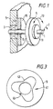
- Figure 1 schematically shows a shaft 1 which is rotatable about its axis as represented by the arrow 7 and which passes through a bearing 3 provided in a support wall 5.
- a first printed circuit board 9 carrying a magnetic field generator (not shown) is mounted for rotation (as represented by arrow 13) with the shaft 1 via a bushing 11 next to a second printed circuit board 15 (shown in cross-section) which carries a number of sense coils (not shown) and an excitation coil (not shown).
- the second printed circuit board 15 is fixed to the support wall 5 and has a central hole 16 through which the rotatable shaft 1 passes.
- the separation between the circuit 59 and the circuit board 15 is between 0.1 and 4 mm in order to obtain reasonably large signals from the sense coils (not shown).
- the arrangement of the magnetic field generator on circuit board 9 and the sense coils on circuit board 15 are such that when the magnetic field generator generates a magnetic field, a signal is induced in each of the sense coils, the peak amplitude of which varies sinusoidally with the angle of rotation of the shaft 1.
- the signals induced in the sense coils are supplied to processing circuitry (not shown) where the rotational angle of the rotatable shaft 1 is determined.
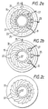
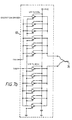
- each sense coil comprises three periods of windings which are circumferentially spaced apart by 20°.
- Figure 2a shows the conductors on the printed circuit board 15 which form these three sense coils 21, 23 and 25.
- Each sense coil 21, 23 and 25 comprises six loops of series connected conductors, connected such that adjacent loops are wound in the opposite sense. This makes the sense coils relatively immune to background electromagnetic interference.
- the angle over which one period of each sense coil extends is 120°.
- the ends of the sense coils 21, 23 and 25, are connected to processing circuitry (not shown) by the twisted wire pairs 27, 29 and 31 respectively.
- Figure 2a also shows the conductor which forms the excitation coil 33 which is connected to excitation circuitry (not shown) by twisted wire pair 35.
- Figures 2b and 2c illustrate the way in which the sense coils 21, 23 and 25 and the excitation coil 33 shown in Figure 2a are formed by a top and bottom layer of printed conductors formed on the printed circuit board 15.
- the conductors on the top and bottom layers are connected, where appropriate, through via holes, some of which are referenced 37.
- Figure 3 shows the conductor on the printed circuit board 9 which forms the magnetic field generator 41.
- the magnetic field generator comprises an electrically resonant circuit 41 having an inductor coil 43 and a capacitor 45.
- Other types of magnetic field generators could be used, such as, a short circuit coil or a conductive plate.
- an AC excitation current is applied to the excitation coil 33 for energising the resonant circuit 41.
- the resonant circuit 41 generates a magnetic field which induces an Electro-Motive Force (EMF) in each of the sense coils 21, 23 and 25, the amplitude of which varies sinusoidally with the relative position between the resonator and the sense coil.
- EMF Electro-Motive Force
- the fundamental frequency of the excitation current applied to the excitation coil 33 corresponds with the resonant frequency of the resonant circuit 41, since this provides the maximum signal output.
- Figure 4 illustrates the way in which the peak amplitude ( ⁇ ) of the EMF's generated in the sense coils 21, 23 and 25 vary with the rotation angle ( ⁇ ) of the resonant circuit 41.
- the respective peak amplitudes 51, 53 and 55 vary sinusoidally and repeat every third of a revolution of the resonant circuit 41 (and hence of the rotatable shaft 1) and are separated by 1/6 of a period from each other. Therefore, the angular position of the rotatable shaft 1 can be determined unambiguously through 120° by suitable processing of the induced signals.
- This position encoder would, therefore, be suitable for determining the angular position of a throttle valve in an engine, which only rotates through 90 degrees.
- FIG. 5 schematically represents excitation and processing circuitry 60 embodying the present invention, which is used to excite the excitation coil 33 and to process the signals induced in the sense coils 21, 23 and 25.
- the excitation signal is generated by the digital waveform generator 61 which receives an oscillating input from a crystal oscillator 63.
- the excitation signal is a squarewave voltage having a fundamental frequency F 0 (e.g. 1MHz) which is applied to an excitation driver 65 which drives the excitation coil 33.
- EMF 21 A 0 COS [ 2 ⁇ ⁇ ] COS [2 ⁇ F 0 t ]
- EMF 23 A 0 COS [ 2 ⁇ ⁇ + ⁇ 3 ] COS [2 ⁇ F 0 t ]
- EMF 25 A 0 COS [ 2 ⁇ ⁇ + 2 ⁇ 3 ] COS [2 ⁇ F 0 t ]
- a 0 is the coupling coefficient between the resonant circuit 41 and the sensor coils 21, 23 and 25, which depends upon, among other things, the separation between the sensor coils 21, 23 and 25 and the resonant circuit 41; ⁇ is the repeat angle, ie, the angle over which one period of each sense coil extends, which, in this embodiment, equals 120°; ⁇ is the rotation angle of the resonant circuit 41 (and hence of the rotatable shaft 1); and F 0 is the fundamental frequency of the excitation current applied to the excitation coil 33.
- the induced EMF's are applied to mixers 71, 73 and 75 respectively, where they are multiplied with signals 81, 83 and 85 respectively.
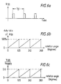
- Each of the mixing signals 81, 83 and 85 comprises two periodic time varying components.
- the first component (V 1 ) is a squarewave corresponding to the squarewave voltage applied to the excitation coil 33 but having a 90° offset to compensate for the phase change due to the resonator 41.
- the second component (V 2 ) is also a squarewave signal but has a lower fundamental frequency F IF (e.g. 10.417 KHz) and, in this embodiment, a phase the same as the above mentioned sense signal phase from the corresponding sense coil 21, 23 or 25.
- the first component effectively demodulates the amplitude modulated EMF induced in the corresponding sense coil and the second component re-modulates it to an intermediate frequency F IF .
- the advantage of using squarewave signals for mixing with the incoming signal from the corresponding sense coil is that the digital waveform generator 61 can multiply these two signals together by simply performing an exclusive-or (XOR) function on the two squarewave components. This is because the high level of the squarewave signal represents positive one and the low level represents negative one. This can be easily verified by considering the truth table of an XOR gate. Additionally, by using squarewave mixing signals, the mixers 71, 73 and 75 can be implemented using an analog CMOS IC switch.
- a periodic squarewave can be represented by the sum of a fundamental sinusoid having the same period as the squarewave and higher order odd harmonics of the fundamental frequency. Therefore, the multiplication being performed in the mixers 71, 73 and 75 can be expressed as follows:
- M 71 A 0 4 ( COS [2 ⁇ F IF t + ⁇ ] + COS [2 ⁇ F IF t - ⁇ ])
- M 73 A 0 4 ( COS [2 ⁇ F IF t + ⁇ + 2 ⁇ 3 ] + COS [2 ⁇ F IF t - ⁇ ])
- M 75 A 0 4 ( COS [2 ⁇ F IF t + ⁇ + 4 ⁇ 3 ] + COS [2 ⁇ F IF t - ⁇ ])
- V OUT 3 A 0 4 ( COS [2 ⁇ F IF t - ⁇ ])
- the output signal from the adder 93 includes a single sinusoid at the intermediate frequency whose phase varies with the angular position ( ⁇ ) of the rotatable shaft.
- the other intermediate frequency components cancel due to the particular choice of the phase of each of the intermediate frequency mixing signals.
- the output V OUT from the adder will also contain high frequency odd harmonic components, but these are removed by the low pass filter 95.
- the single intermediate frequency component in V OUT is then supplied to the comparator 97, where it is converted into a corresponding squarewave by comparing it with a reference voltage V REF .
- the squarewave signal output by the comparator 97 is applied to the reset input (R) of a set-reset latch 99.
- the set input (S) of the latch 99 receives a squarewave signal 100 generated by the digital waveform generator 61.
- the squarewave signal 100 has the same fundamental frequency F IF and phase as the second mixing component V 2 applied to mixer 71.
- the squarewave signal 100 may be passed through a low pass filter corresponding to low pass filter 95 and then compared with the reference voltage V REF prior to being applied to the set input of the latch 99. This reduces the effect of offset errors caused by temperature drift of the electronic components, since both signals applied to the input of the latch 99 will have been processed by similar electronics.
- Figure 6a shows the resulting Q output signal 101 from the latch 99.
- output signal 101 is a periodic squarewave signal having a period (T IF ) the same as the second mixing components V 2 applied to the mixers 71, 73 and 75 and a duty ratio which varies with the angular position ( ⁇ ) of the rotatable shaft 1.
- Figure 6b illustrates the way in which the duty ratio of the output signal 101 (V 101 ) varies with the rotation angle of the rotatable shaft. As shown, the duty ratio varies in a sawtooth manner, repeating every 120° of rotation of the rotatable shaft 1.
- the output signal 101 from the latch 99 is also applied to the input of a low pass filter 103 which removes all the time varying components to leave an output signal 105 representing the amount of DC signal present in the output signal 101.
- the ratio of the output signal 105 (V 105 ) to the supply voltage V supply also varies in a sawtooth manner (with a maximum value of 0.6), repeating every 120° of rotation of the rotatable shaft 1.
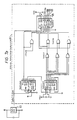
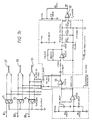
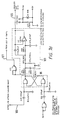
- Figures 7a-7d illustrate a circuit diagram of the excitation and processing circuitry 60 schematically shown in Figure 5.
- Figure 7a is a circuit diagram showing the crystal oscillator 63 and the digital waveform generator 61.
- the crystal oscillator 63 generates a 4 MHz signal which is applied to various counters and logic gates of the digital waveform generator 61.
- the waveform generator 61 outputs two signals TXA and TXB which are applied to the excitation driver 65 shown in Figure 7b and signals 100, 81, 83 and 85 which are used in the processing circuitry.
- Figure 7b illustrates the circuit diagram of the excitation driver 65 which receives the signals TXA and TXB from the digital waveform generator 61 and outputs the excitation signal to the twisted wire pair 35 which, as shown in Figure 2a, is connected to the excitation coil 33.
- Figure 7c is a circuit diagram showing part of the processing circuitry shown in Figure 5. As shown, the ends of the twisted wire pairs 27, 29 and 31 are connected to the input of a triple change over CMOS switch which forms the mixers 71, 73 and 75. The CMOS switch also receives signals 81, 83 and 85 output from the digital waveform generator 61 shown in Figure 7a. Figure 7c also shows the adder 93 which adds the signals from the mixers 71, 73 and 75, the low pass filter 95 which filters out the high frequency odd harmonic components from the output of the adder 93 and the comparator 97 which compares the filtered output signal with a reference voltage V REF . As illustrated in Figure 7c, the reference voltage V REF equals 2.5 volts, since the input signal varies between zero and positive five volts.
- Figure 7d shows a circuit diagram of the rest of the processing circuitry shown in Figure 5.
- Figure 7d shows the set-reset latch 99 and the low pass filter 103 used to filter the output signal 101 from the latch 99 to produce the output signal 105.
- the processing circuitry described above is able to produce an output signal which varies in dependence upon the rotational position ( ⁇ ) of the rotatable shaft which is relatively insensitive to variations in the gap between the sense coils 21, 23 and 25 and the resonant circuit 41. This is because the phase of the output signal from the low pass filter 95 does not depend upon the abovementioned coupling coefficient A 0 .
- the processing circuitry 60 described above also has the advantage that it continuously outputs a signal which is indicative of the rotational angle of the rotatable shaft 1. Whereas, with the processing circuitry described in WO95/31696, the abovementioned arc-tangent calculation has to be performed each time a position measurement is required in order to generate an output signal.
- the processing circuitry could be adapted to receive and process signals from any number of sense coils. Additionally, as those skilled in the art will appreciate, it is not necessary for the sense coils to be evenly spaced over the measurement path. Further still, a different weighting could be applied to the signals output from the different mixers.
- the output of the low pass filter 95 will have the following general form:
- the position encoder described in the above embodiment is a rotary position encoder
- the above processing circuitry could be used for processing the signals from a linear position encoder or a radial position encoder, such as those described in the applicant's earlier International Patent Application WO95/31696.
- the processing circuitry described above could be used to process the signals from a position encoder which uses capacitive coupling or to process the signals from a position encoder which has direct contact between the two relatively movable members.
Landscapes
- Engineering & Computer Science (AREA)
- Theoretical Computer Science (AREA)
- Physics & Mathematics (AREA)
- General Physics & Mathematics (AREA)
- Power Engineering (AREA)
- Transmission And Conversion Of Sensor Element Output (AREA)
- Automatic Control Of Machine Tools (AREA)
- Control Of Stepping Motors (AREA)
- Rotational Drive Of Disk (AREA)
- Electrical Discharge Machining, Electrochemical Machining, And Combined Machining (AREA)
- Analogue/Digital Conversion (AREA)
- Pulleys (AREA)
- Threshing Machine Elements (AREA)
- Iron Core Of Rotating Electric Machines (AREA)
Applications Claiming Priority (3)
| Application Number | Priority Date | Filing Date | Title |
|---|---|---|---|
| GB9613673 | 1996-06-28 | ||
| GBGB9613673.4A GB9613673D0 (en) | 1996-06-28 | 1996-06-28 | Rotary spiral improvements |
| PCT/GB1997/001762 WO1998000921A2 (en) | 1996-06-28 | 1997-06-30 | Apparatus and method for processing signals obtained from a position encoder |
Publications (2)
| Publication Number | Publication Date |
|---|---|
| EP0907878A2 EP0907878A2 (en) | 1999-04-14 |
| EP0907878B1 true EP0907878B1 (en) | 2002-09-25 |
Family
ID=10796087
Family Applications (1)
| Application Number | Title | Priority Date | Filing Date |
|---|---|---|---|
| EP97929398A Expired - Lifetime EP0907878B1 (en) | 1996-06-28 | 1997-06-30 | Apparatus and method for processing signals obtained from a position encoder |
Country Status (9)
| Country | Link |
|---|---|
| EP (1) | EP0907878B1 (https=) |
| JP (1) | JP2001502416A (https=) |
| AT (1) | ATE225030T1 (https=) |
| AU (1) | AU3351897A (https=) |
| CA (1) | CA2259191A1 (https=) |
| DE (1) | DE69715848T2 (https=) |
| ES (1) | ES2184105T3 (https=) |
| GB (1) | GB9613673D0 (https=) |
| WO (1) | WO1998000921A2 (https=) |
Families Citing this family (24)
| Publication number | Priority date | Publication date | Assignee | Title |
|---|---|---|---|---|
| US20030062889A1 (en) | 1996-12-12 | 2003-04-03 | Synaptics (Uk) Limited | Position detector |
| WO2000033244A2 (en) | 1998-11-27 | 2000-06-08 | Synaptics (Uk) Limited | Position sensor |
| US6788221B1 (en) | 1996-06-28 | 2004-09-07 | Synaptics (Uk) Limited | Signal processing apparatus and method |
| GB9720954D0 (en) * | 1997-10-02 | 1997-12-03 | Scient Generics Ltd | Commutators for motors |
| GB9811151D0 (en) * | 1998-05-22 | 1998-07-22 | Scient Generics Ltd | Rotary encoder |
| US7019672B2 (en) | 1998-12-24 | 2006-03-28 | Synaptics (Uk) Limited | Position sensor |
| DE19950902A1 (de) | 1999-10-22 | 2001-05-23 | Ds Technologie Werkzeugmaschb | System und Verfahren zur Steuerung einer Positioniereinrichtung, insbesondere von Stellantrieben bei Werkzeugmaschinen, sowie Phasenmischvorrichtung |
| WO2001042865A1 (en) | 1999-12-10 | 2001-06-14 | Gentech Investment Group Ag. | Man-machine interface having relative position sensor |
| EP1412912B1 (en) | 2001-05-21 | 2008-06-18 | Synaptics (UK) Limited | Position sensor |
| GB0126014D0 (en) | 2001-10-30 | 2001-12-19 | Sensopad Technologies Ltd | Modulated field position sensor |
| US7196604B2 (en) | 2001-05-30 | 2007-03-27 | Tt Electronics Technology Limited | Sensing apparatus and method |
| GB2403017A (en) | 2002-03-05 | 2004-12-22 | Synaptics | Position sensor |
| WO2004036147A2 (en) | 2002-10-16 | 2004-04-29 | Tt Electronics Technology Limited | Position sensing apparatus and method |
| GB2394293A (en) | 2002-10-16 | 2004-04-21 | Gentech Invest Group Ag | Inductive sensing apparatus and method |
| GB0303627D0 (en) | 2003-02-17 | 2003-03-19 | Sensopad Technologies Ltd | Sensing method and apparatus |
| GB0317370D0 (en) | 2003-07-24 | 2003-08-27 | Synaptics Uk Ltd | Magnetic calibration array |
| EP1807749A1 (en) | 2004-09-24 | 2007-07-18 | Wacom Corporation Limited | An electronic device having a position sensor |
| EP1898185B1 (en) * | 2005-06-26 | 2016-11-09 | Amiteq Co., Ltd. | Position sensor |
| GB2488389C (en) | 2010-12-24 | 2018-08-22 | Cambridge Integrated Circuits Ltd | Position sensing transducer |
| GB2503006B (en) | 2012-06-13 | 2017-08-09 | Cambridge Integrated Circuits Ltd | Position sensing transducer |
| DE102017210655B4 (de) * | 2017-06-23 | 2023-12-21 | Robert Bosch Gmbh | Drehwinkelsensor |
| DE102018102094A1 (de) * | 2018-01-31 | 2019-08-01 | Thyssenkrupp Ag | Induktiver Winkelsensor für eine Kraftfahrzeuglenkung |
| FR3077880B1 (fr) * | 2018-02-15 | 2020-01-17 | Continental Automotive France | Capteur de couple integrant un capteur de position angulaire d'un element en rotation |
| CN119197332B (zh) * | 2024-09-25 | 2025-04-18 | 天津大学 | 一种f-p腔正交检测的高精度微位移测量装置及方法 |
Family Cites Families (3)
| Publication number | Priority date | Publication date | Assignee | Title |
|---|---|---|---|---|
| US3482242A (en) * | 1966-05-25 | 1969-12-02 | Computing Devices Canada | Synchro to digital converter using storage capacitors and sampling circuits |
| JPS60165512A (ja) * | 1984-02-08 | 1985-08-28 | Toshiba Corp | デイジタル回転角検出器 |
| CN1085332C (zh) * | 1994-05-14 | 2002-05-22 | 辛纳普蒂克斯(英国)有限公司 | 位置编码器 |
-
1996
- 1996-06-28 GB GBGB9613673.4A patent/GB9613673D0/en active Pending
-
1997
- 1997-06-30 ES ES97929398T patent/ES2184105T3/es not_active Expired - Lifetime
- 1997-06-30 AT AT97929398T patent/ATE225030T1/de not_active IP Right Cessation
- 1997-06-30 DE DE69715848T patent/DE69715848T2/de not_active Expired - Fee Related
- 1997-06-30 CA CA002259191A patent/CA2259191A1/en not_active Abandoned
- 1997-06-30 WO PCT/GB1997/001762 patent/WO1998000921A2/en not_active Ceased
- 1997-06-30 AU AU33518/97A patent/AU3351897A/en not_active Abandoned
- 1997-06-30 EP EP97929398A patent/EP0907878B1/en not_active Expired - Lifetime
- 1997-06-30 JP JP10503926A patent/JP2001502416A/ja active Pending
Also Published As
| Publication number | Publication date |
|---|---|
| ATE225030T1 (de) | 2002-10-15 |
| DE69715848D1 (de) | 2002-10-31 |
| AU3351897A (en) | 1998-01-21 |
| WO1998000921A3 (en) | 1998-04-23 |
| HK1019089A1 (en) | 2000-01-21 |
| EP0907878A2 (en) | 1999-04-14 |
| GB9613673D0 (en) | 1996-08-28 |
| DE69715848T2 (de) | 2003-05-22 |
| JP2001502416A (ja) | 2001-02-20 |
| ES2184105T3 (es) | 2003-04-01 |
| WO1998000921A2 (en) | 1998-01-08 |
| CA2259191A1 (en) | 1998-01-08 |
Similar Documents
| Publication | Publication Date | Title |
|---|---|---|
| EP0907878B1 (en) | Apparatus and method for processing signals obtained from a position encoder | |
| US6788221B1 (en) | Signal processing apparatus and method | |
| EP1078226B1 (en) | Position sensor | |
| US6522128B1 (en) | Position sensor having compact arrangement of coils | |
| US12013300B2 (en) | Torque sensing device and method | |
| US11525702B2 (en) | Sensor system for determining at least one rotation characteristic of a rotating element | |
| EP1020018B1 (en) | Motor control system and method | |
| EP2145158B1 (en) | Transducer | |
| US6236199B1 (en) | Inductive angle sensor | |
| CN112461108B (zh) | 感应位置传感装置及其方法 | |
| RU2015132476A (ru) | Позиционное кодирующее устройство и способ определения положения подвижной части механизма | |
| KR20040075860A (ko) | 감지장치 및 감지방법 | |
| EP1042650B1 (en) | Signal processing apparatus and method | |
| EP1789756A2 (en) | Sensing apparatus and method | |
| HK1019089B (en) | Apparatus and method for processing signals obtained from a position encoder | |
| HK1030982B (en) | Signal processing apparatus and method | |
| JPH07239247A (ja) | 磁気エンコーダの信号処理装置 | |
| HK40044429A (en) | Inductive position sensing apparatus and method for the same | |
| HK40044429B (en) | Inductive position sensing apparatus and method for the same | |
| JPS63157693A (ja) | ステツプモ−タの回転位置検出器 |
Legal Events
| Date | Code | Title | Description |
|---|---|---|---|
| PUAI | Public reference made under article 153(3) epc to a published international application that has entered the european phase |
Free format text: ORIGINAL CODE: 0009012 |
|
| 17P | Request for examination filed |
Effective date: 19990120 |
|
| AK | Designated contracting states |
Kind code of ref document: A2 Designated state(s): AT BE CH DE DK ES FI FR GB GR IE IT LI LU MC NL PT SE |
|
| RAP1 | Party data changed (applicant data changed or rights of an application transferred) |
Owner name: ABSOLUTE SENSORS LIMITED |
|
| RAP1 | Party data changed (applicant data changed or rights of an application transferred) |
Owner name: SYNAPTICS (UK) LIMITED |
|
| GRAG | Despatch of communication of intention to grant |
Free format text: ORIGINAL CODE: EPIDOS AGRA |
|
| 17Q | First examination report despatched |
Effective date: 20010430 |
|
| GRAG | Despatch of communication of intention to grant |
Free format text: ORIGINAL CODE: EPIDOS AGRA |
|
| GRAG | Despatch of communication of intention to grant |
Free format text: ORIGINAL CODE: EPIDOS AGRA |
|
| GRAH | Despatch of communication of intention to grant a patent |
Free format text: ORIGINAL CODE: EPIDOS IGRA |
|
| GRAH | Despatch of communication of intention to grant a patent |
Free format text: ORIGINAL CODE: EPIDOS IGRA |
|
| GRAA | (expected) grant |
Free format text: ORIGINAL CODE: 0009210 |
|
| AK | Designated contracting states |
Kind code of ref document: B1 Designated state(s): AT BE CH DE DK ES FI FR GB GR IE IT LI LU MC NL PT SE |
|
| PG25 | Lapsed in a contracting state [announced via postgrant information from national office to epo] |
Ref country code: NL Free format text: LAPSE BECAUSE OF FAILURE TO SUBMIT A TRANSLATION OF THE DESCRIPTION OR TO PAY THE FEE WITHIN THE PRESCRIBED TIME-LIMIT Effective date: 20020925 Ref country code: LI Free format text: LAPSE BECAUSE OF FAILURE TO SUBMIT A TRANSLATION OF THE DESCRIPTION OR TO PAY THE FEE WITHIN THE PRESCRIBED TIME-LIMIT Effective date: 20020925 Ref country code: GR Free format text: LAPSE BECAUSE OF FAILURE TO SUBMIT A TRANSLATION OF THE DESCRIPTION OR TO PAY THE FEE WITHIN THE PRESCRIBED TIME-LIMIT Effective date: 20020925 Ref country code: FI Free format text: LAPSE BECAUSE OF FAILURE TO SUBMIT A TRANSLATION OF THE DESCRIPTION OR TO PAY THE FEE WITHIN THE PRESCRIBED TIME-LIMIT Effective date: 20020925 Ref country code: CH Free format text: LAPSE BECAUSE OF FAILURE TO SUBMIT A TRANSLATION OF THE DESCRIPTION OR TO PAY THE FEE WITHIN THE PRESCRIBED TIME-LIMIT Effective date: 20020925 Ref country code: BE Free format text: LAPSE BECAUSE OF FAILURE TO SUBMIT A TRANSLATION OF THE DESCRIPTION OR TO PAY THE FEE WITHIN THE PRESCRIBED TIME-LIMIT Effective date: 20020925 Ref country code: AT Free format text: LAPSE BECAUSE OF FAILURE TO SUBMIT A TRANSLATION OF THE DESCRIPTION OR TO PAY THE FEE WITHIN THE PRESCRIBED TIME-LIMIT Effective date: 20020925 |
|
| REF | Corresponds to: |
Ref document number: 225030 Country of ref document: AT Date of ref document: 20021015 Kind code of ref document: T |
|
| REG | Reference to a national code |
Ref country code: GB Ref legal event code: FG4D |
|
| REG | Reference to a national code |
Ref country code: CH Ref legal event code: EP |
|
| REG | Reference to a national code |
Ref country code: IE Ref legal event code: FG4D |
|
| REF | Corresponds to: |
Ref document number: 69715848 Country of ref document: DE Date of ref document: 20021031 |
|
| PG25 | Lapsed in a contracting state [announced via postgrant information from national office to epo] |
Ref country code: SE Free format text: LAPSE BECAUSE OF FAILURE TO SUBMIT A TRANSLATION OF THE DESCRIPTION OR TO PAY THE FEE WITHIN THE PRESCRIBED TIME-LIMIT Effective date: 20021225 Ref country code: DK Free format text: LAPSE BECAUSE OF FAILURE TO SUBMIT A TRANSLATION OF THE DESCRIPTION OR TO PAY THE FEE WITHIN THE PRESCRIBED TIME-LIMIT Effective date: 20021225 |
|
| PG25 | Lapsed in a contracting state [announced via postgrant information from national office to epo] |
Ref country code: PT Free format text: LAPSE BECAUSE OF FAILURE TO SUBMIT A TRANSLATION OF THE DESCRIPTION OR TO PAY THE FEE WITHIN THE PRESCRIBED TIME-LIMIT Effective date: 20021226 |
|
| ET | Fr: translation filed | ||
| NLV1 | Nl: lapsed or annulled due to failure to fulfill the requirements of art. 29p and 29m of the patents act | ||
| REG | Reference to a national code |
Ref country code: ES Ref legal event code: FG2A Ref document number: 2184105 Country of ref document: ES Kind code of ref document: T3 |
|
| REG | Reference to a national code |
Ref country code: CH Ref legal event code: PL |
|
| PG25 | Lapsed in a contracting state [announced via postgrant information from national office to epo] |
Ref country code: MC Free format text: LAPSE BECAUSE OF NON-PAYMENT OF DUE FEES Effective date: 20030630 Ref country code: LU Free format text: LAPSE BECAUSE OF NON-PAYMENT OF DUE FEES Effective date: 20030630 Ref country code: IE Free format text: LAPSE BECAUSE OF NON-PAYMENT OF DUE FEES Effective date: 20030630 |
|
| PLBE | No opposition filed within time limit |
Free format text: ORIGINAL CODE: 0009261 |
|
| STAA | Information on the status of an ep patent application or granted ep patent |
Free format text: STATUS: NO OPPOSITION FILED WITHIN TIME LIMIT |
|
| 26N | No opposition filed |
Effective date: 20030626 |
|
| REG | Reference to a national code |
Ref country code: IE Ref legal event code: MM4A |
|
| PGFP | Annual fee paid to national office [announced via postgrant information from national office to epo] |
Ref country code: ES Payment date: 20040623 Year of fee payment: 8 |
|
| PG25 | Lapsed in a contracting state [announced via postgrant information from national office to epo] |
Ref country code: IT Free format text: LAPSE BECAUSE OF NON-PAYMENT OF DUE FEES Effective date: 20050630 |
|
| PG25 | Lapsed in a contracting state [announced via postgrant information from national office to epo] |
Ref country code: ES Free format text: LAPSE BECAUSE OF NON-PAYMENT OF DUE FEES Effective date: 20050701 |
|
| REG | Reference to a national code |
Ref country code: ES Ref legal event code: FD2A Effective date: 20050701 |
|
| PGFP | Annual fee paid to national office [announced via postgrant information from national office to epo] |
Ref country code: FR Payment date: 20090506 Year of fee payment: 13 |
|
| PGFP | Annual fee paid to national office [announced via postgrant information from national office to epo] |
Ref country code: GB Payment date: 20090529 Year of fee payment: 13 Ref country code: DE Payment date: 20090812 Year of fee payment: 13 |
|
| GBPC | Gb: european patent ceased through non-payment of renewal fee |
Effective date: 20100630 |
|
| REG | Reference to a national code |
Ref country code: FR Ref legal event code: ST Effective date: 20110228 |
|
| PG25 | Lapsed in a contracting state [announced via postgrant information from national office to epo] |
Ref country code: DE Free format text: LAPSE BECAUSE OF NON-PAYMENT OF DUE FEES Effective date: 20110101 |
|
| PG25 | Lapsed in a contracting state [announced via postgrant information from national office to epo] |
Ref country code: FR Free format text: LAPSE BECAUSE OF NON-PAYMENT OF DUE FEES Effective date: 20100630 |
|
| PG25 | Lapsed in a contracting state [announced via postgrant information from national office to epo] |
Ref country code: GB Free format text: LAPSE BECAUSE OF NON-PAYMENT OF DUE FEES Effective date: 20100630 |