EP0907797B1 - Verfahren und vorrichtung zur herstellung von weichem tissuepapier - Google Patents
Verfahren und vorrichtung zur herstellung von weichem tissuepapier Download PDFInfo
- Publication number
- EP0907797B1 EP0907797B1 EP97924516A EP97924516A EP0907797B1 EP 0907797 B1 EP0907797 B1 EP 0907797B1 EP 97924516 A EP97924516 A EP 97924516A EP 97924516 A EP97924516 A EP 97924516A EP 0907797 B1 EP0907797 B1 EP 0907797B1
- Authority
- EP
- European Patent Office
- Prior art keywords
- air
- percent
- fabric
- web
- plenum
- Prior art date
- Legal status (The legal status is an assumption and is not a legal conclusion. Google has not performed a legal analysis and makes no representation as to the accuracy of the status listed.)
- Expired - Lifetime
Links
Images


Classifications
-
- D—TEXTILES; PAPER
- D21—PAPER-MAKING; PRODUCTION OF CELLULOSE
- D21F—PAPER-MAKING MACHINES; METHODS OF PRODUCING PAPER THEREON
- D21F11/00—Processes for making continuous lengths of paper, or of cardboard, or of wet web for fibre board production, on paper-making machines
- D21F11/006—Making patterned paper
-
- D—TEXTILES; PAPER
- D21—PAPER-MAKING; PRODUCTION OF CELLULOSE
- D21F—PAPER-MAKING MACHINES; METHODS OF PRODUCING PAPER THEREON
- D21F1/00—Wet end of machines for making continuous webs of paper
- D21F1/48—Suction apparatus
-
- D—TEXTILES; PAPER
- D21—PAPER-MAKING; PRODUCTION OF CELLULOSE
- D21F—PAPER-MAKING MACHINES; METHODS OF PRODUCING PAPER THEREON
- D21F1/00—Wet end of machines for making continuous webs of paper
- D21F1/48—Suction apparatus
- D21F1/52—Suction boxes without rolls
-
- D—TEXTILES; PAPER
- D21—PAPER-MAKING; PRODUCTION OF CELLULOSE
- D21F—PAPER-MAKING MACHINES; METHODS OF PRODUCING PAPER THEREON
- D21F11/00—Processes for making continuous lengths of paper, or of cardboard, or of wet web for fibre board production, on paper-making machines
- D21F11/14—Making cellulose wadding, filter or blotting paper
Definitions
- tissue products such as bath and facial tissue that must be considered in producing a final product having desirable attributes that make it suitable and preferred for the product's intended purpose
- improved softness of the product has long been one major objective, and this has been a particularly significant factor for the success of premium products.
- the major components of softness include stiffness and bulk (density), with lower stiffness and higher bulk (lower density) generally improving perceived softness.
- WO 95/00706 A relates to a method of making a soft tissue sheet comprising forming an aqueous suspension of papermaking fibers, mechanically working the suspension, diluting the aqueous suspension of curled fibers to a consistency of about 0,5 percent or less, depositing the diluted aqueous suspension onto a forming fabric to form a wet web, dewatering the wet web to a consistency of from about 20 to about 30 percent, transferring the dewatered web from the forming fabric to a throughdrying fabric, and throughdrying the web to final dryness.
- US-A-5,048,589 discloses hand or wiper towels produced by a process including the steps of (1) forming a furnish of cellulosic fibers, water and a chemical bonder, (2) depositing the furnish on a traveling foraminous belt traveling at a speed up to about 10 % slower than the first foraminous belt, thereby forming a fibrous web on top of the traveling belt, (3) subjecting the fibrous web to non-compressive drying to remove the water form the fibrous web, and (4) removing the dried fibrous web from the traveling foraminous belt.
- an improved uncreped throughdried web can be made by dewatering the web to greater than about 30 percent consistency prior to transferring the wet web from a forming fabric to one or more slower speed intermediate transfer fabrics before further transferring the web to a throughdrying fabric for final drying of the web.
- increasing the consistency of the uncreped throughdried web before the point of differential speed transfer has surprisingly been found to result in: (1) both higher machine direction and cross direction tensile properties, contributing to improved runnability of the web; and (2) reduced modulus, that is increased softness, when the tensile strength is adjusted to the normal value.
- One particularly desirable means by which the web can be dewatered to greater than about 30 percent consistency comprises an air press located just upstream of the differential speed transfer. While pressurized fluid jets in combination with a vacuum device have previously been discussed in the patent literature, such devices have not been widely used in tissue manufacturing. Principally, this appears to be due to the fact that it had not been previously recognized that dewatering the web to greater than about 30 percent consistency in advance of the differential speed transfer would result in the improved product properties identified herein. Moreover, the disincentive to using such equipment is also believed to be attributable to the difficulties of actual implementation, including disintegration of the tissue web, pressurized fluid leaks, seal and/or fabric wear, and the like.
- the air press used in the present method overcomes these difficulties and provides one practical apparatus for achieving the desired consistency ahead of the differential speed transfer.
- the invention resides in a method of making a soft tissue sheet.
- the method includes the steps of: depositing an aqueous suspension of papermaking fibers onto an endless forming fabric to form a wet web; dewatering the wet web to a consistency of from about 20 to about 30 percent; supplementally dewatering the wet web using noncompressive dewatering means to a consistency of greater than about 30 percent; transferring the supplementally dewatered web to a transfer fabric traveling at a speed of from about 10 to about 80 percent slower than the forming fabric; transferring the web to a throughdrying fabric; and throughdrying the web to a final dryness.
- the air press desirably provides a pressure differential across the wet web of from about 35 to about 60 inches of mercury. This may be achieved in part by an air plenum of the air press maintaining a fluid pressure on one side of the wet web of from about 5 to about 60 pounds per square inch, and particularly from about 5 to about 30 pounds per square inch.
- the pressurized fluid may be air at ambient temperature, heated air, steam, or the like.
- the air press may be operable to increase the consistency of the wet web by at least about 3 and preferably at least about 5 percent.
- Optional steam showers may be employed before the air press to increase post air press consistency.
- the air press includes an air plenum comprising a plenum cover having a bottom surface and a vacuum box comprising a vacuum box cover having a top surface positioned in close proximity to the bottom surface of the plenum cover.
- the air press also includes means for supplying pressurized fluid to the air plenum and means for applying vacuum to the vacuum box.
- Side seal members of the air press are adapted to reside in contact with the air plenum and the vacuum box for minimizing the escape of the pressurized fluid.
- the side seal members are attached to one of the air plenum and the vacuum box, and are positioned in close proximity to side seal contact surfaces defined by the other of the air plenum and the vacuum box.
- the side seal members are adapted to flex into sealing contact with the side seal contact surface upon exposure to the pressurized fluid to enhance the seal effectiveness.
- the air press may include a position control mechanism that functions to maintain the air plenum in close proximity to the vacuum box.
- the position control mechanism desirably includes a rotatably mounted lever attached to the air plenum, and a counterbalance cylinder attached to the lever.
- the position control mechanism is adapted to rotate the lever to counteract pressure changes within the air plenum. In this way, the air plenum resides in close proximity to or in contact with the fabrics passing between the air plenum and the vacuum box, without clamping the fabrics therebetween.
- the air press in another embodiment, includes an air plenum comprising a plenum cover having a bottom surface, and means for supplying pressurized fluid to the air plenum.
- the air press also includes a vacuum box comprising a vacuum box cover having a top surface positioned in close proximity to the bottom surface of the plenum cover, and means for applying vacuum to the vacuum box.
- An arm that is pivotally mounted on the air plenum comprises first and second portions, with the first portion of the arm being disposed at least partially inside the air plenum.
- a sealing bar is formed from or mounted on the first portion of the arm.
- the air press also includes means for pivoting the arm in response to fluid pressure within the air plenum.
- the sealing bar portion of the pivotable arm acts as an end seal to prevent the escape of pressurized fluid from between the air plenum and the vacuum box.
- the sealing bar may conform to fabric irregularities or misalignment of the supporting structure.
- the end seals which are also referred to as cross direction or CD seals, improve containment of the pressurized fluid and thus result in more efficient operation of the air press.
- the loading of the end seals is controlled to maintain the sealing bar in contact with the underlying moving fabric, without causing undue wear of the fabric.
- the present method and apparatus are capable of functioning at commercially viable web speeds.
- the forming fabric may be controlled to travel at speeds of at least about 10 meter per second (2000 feet per minute (fpm)), and more desirably at speeds of at least about 20 meter per second (4000 fpm).
- the intermediate transfer fabric or fabrics are traveling at a slower speed than the forming fabric during the transfer in order to impart stretch into the sheet.
- speed differential between the forming fabric and the slower transfer fabric is increased (sometimes referred to as "negative draw” or "rush transfer"), the stretch imparted to the web during transfer is also increased.
- the transfer fabric can be relatively smooth and dense compared to the coarse weave of a typical throughdrying fabric.
- the transfer fabric is as fine as can be run from a practical standpoint. Gripping of the web is accomplished by the presence of knuckles on the surface of the transfer fabric.
- one or more of the wet web transfers are achieved using a "fixed gap” or “kiss” transfer in which the fabrics simultaneously converge and diverge, which will be hereinafter described in detail.
- Such transfers not only avoid any significant compaction of the web while it is in a wet bond-forming state, but when used in combination with a differential speed transfer and/or a smooth transfer fabric, are observed to smoothen the surface of the web and final dry sheet.
- the speed difference between the forming fabric and the transfer fabric can be from about 10 to about 80 percent or greater, preferably from about 10 to about 35 percent, and more preferably from about 15 to about 25 percent, with the transfer fabric being the slower fabric.
- the optimum speed differential will depend on a variety of factors, including the particular type of product being made. As previously mentioned, the increase in stretch imparted to the web is proportional to the speed differential. For an uncreped throughdried three-ply wiper having a basis weight of about 20 grams per square meter per ply, for example, a speed differential in the production of each ply of from about 20 to about 25 percent between the forming fabric and a sole transfer fabric produces a stretch in the final product of from about 15 to about 20 percent.
- the stretch can be imparted to the web using a single differential speed transfer or two or more differential speed transfers of the wet web prior to drying. Hence there can be one or more transfer fabrics.
- the amount of stretch imparted to the web can hence be divided among one, two, three or more differential speed transfers.
- the transfer is desirably carried out such that the resulting "sandwich" (consisting of the forming fabric/web/transfer fabric) exists for as short a duration as possible. In particular, it exists only at the leading edge of the vacuum shoe or transfer shoe slot being used to effect the transfer. In effect, the forming fabric and the transfer fabric converge and diverge at the leading edge of the vacuum slot. The intent is to minimize the distance over which the web is in simultaneous contact with both fabrics. It has been found that simultaneous convergence/divergence is the key to eliminating macrofolds and thereby enhances the smoothness of the resulting tissue or other product.
- the simultaneous convergence and divergence of the two fabrics will only occur at the leading edge of the vacuum slot if a sufficient angle of convergence is maintained between the two fabrics as they approach the leading edge of the vacuum slot and if a sufficient angle of divergence is maintained between the two fabrics on the downstream side of the vacuum slot.
- the minimum angles of convergence and divergence are about 0.5 degree or greater, more specifically about 1 degree or greater, more specifically about 2 degrees or greater, and still more specifically about 5 degrees or greater.
- the angles of convergence and divergence can be the same or different. Greater angles provide a greater margin of error during operation.
- a suitable range is from about 1 degree to about 10 degrees.
- the distance between the fabrics should be equal to or greater than the thickness or caliper of the web so that the web is not significantly compressed when transferred at the leading edge of the vacuum slot.
- Increased smoothness is achieved by use of the air press upstream of the differential speed transfer. This is most preferably used in combination with a fixed gap carrier fabric section following drying. Calendering of the web is not necessary to obtain desirable levels of smoothness, but further processing of the sheet, such as by calendering, embossing or creping, may be beneficial to further enhance the sheet properties.
- transfer fabric is a fabric which is positioned between the forming section and the drying section of the web manufacturing process.
- Suitable transfer fabrics are those papermaking fabrics which provide a high fiber support index and provide a good vacuum seal to maximize fabric/sheet contact during transfer from the forming fabric.
- the fabric can have a relatively smooth surface contour to impart smoothness to the web, yet must have enough texture to grab the web and maintain contact during a rush transfer. Finer fabrics can produce a higher degree of stretch in the web, which is desirable for some product applications.
- Transfer fabrics include single-layer, multi-layer, or composite permeable structures.
- Preferred fabrics have at least some of the following characteristics: (1) On the side of the transfer fabric that is in contact with the wet web (the top side), the number of machine direction (MD) strands per cm (mesh) is from 4 to 80 (10 to 200 per inch) and the number of cross-machine direction (CD) strands per cm (count) is also from 4 to 80 (10 to 200 per inch). The strand diameter is typically smaller than 0.2mm (0.050 inch) (2) On the top side, the distance between the highest point of the MD knuckle and the highest point of the CD knuckle is from about 25 ⁇ m to about 0.5 or 0.75 mm (about 0.001 to about 0.02 or 0.03 inch).
- the fabric In between these two levels, there can be knuckles formed either by MD or CD strands that give the topography a 3-dimensional characteristic; (3) On the top side, the length of the MD knuckles is equal to or longer than the length of the CD knuckles; (4) If the fabric is made in a multi-layer construction, it is preferred that the bottom layer is of a finer mesh than the top layer so as to control the depth of web penetration and to maximize fiber retention; and (5) The fabric may be made to show certain geometric patterns that are pleasing to the eye, which typically repeat between every 2 to 50 warp yarns.
- transfer fabrics include, by way of example, those made by Asten Forming Fabrics, Inc., Appleton, Wisconsin and designated as numbers 934, 937, 939 and 959.
- Particular transfer fabrics that may be used also include the fabrics disclosed in U.S. Patent 5,429,686 issued July 4, 1995, to Chiu et al., which is incorporated herein by reference.
- the void volume of the transfer fabric can be equal to or less than the fabric from which the web is transferred.
- the forming process and tackle can be conventional as is well known in the papermaking industry.
- Such formation processes include Fourdrinier, roof formers (such as suction breast roll), gap formers (such as twin wire formers, crescent formers), or the like.
- Forming wires or fabrics can also be conventional, with the finer weaves with greater fiber support being preferred to produce a more smooth sheet or web. Headboxes used to deposit the fibers onto the forming fabric can be layered or nonlayered.
- tissue web which includes webs for making facial tissue, bath tissue, paper towels, dinner napkins, or the like.
- tissue webs can be single-ply products or multi-ply products, such as two-ply, three-ply, four-ply or greater.
- One-ply products are advantageous because of their lower cost of manufacture, while multi-ply products are preferred by many consumers.
- multi-ply products it is not necessary that all plies of the product be the same, provided at least one ply is in accordance with this invention.
- the webs can be layered or unlayered (blended), and the fibers making up the web can be any fibers suitable for papermaking.
- Suitable basis weights for these tissue webs can be from about 5 to about 70 grams per square meter (gsm), preferably from about 10 to about 40 gsm, and more preferably from about 20 to about 30 gsm.
- gsm grams per square meter
- a basis weight of about 25 gsm is preferred.
- a basis weight of about 20 gsm per ply is preferred.
- a basis weight of about 15 gsm per ply is preferred.
- higher basis weight webs will require lower air flow to maintain the same operating pressure in the air plenum.
- the width of the slots of the air press are desirably adjusted to match the system to the available air capacity, with wider slots used for heavier basis weight webs.
- the drying process can be any noncompressive drying method which tends to preserve the bulk or thickness of the wet web including, without limitation, throughdrying, infra-red irradiation, microwave drying, or the like. Because of its commercial availability and practicality, throughdrying is a well-known and preferred means for noncompressively drying the web. Suitable throughdrying fabrics include, without limitation, Asten 920A and 937A, and Velostar P800 and 103A. The throughdrying fabrics may also include those disclosed in U.S. Patent 5,429,686 issued July 4, 1995, to Chiu et al. The web is preferably dried to final dryness without creping, since creping tends to lower the web strength and bulk.
- transfer fabric and throughdrying fabric can make separate and independent contributions to final sheet properties.
- sheet surface smoothness as determined by a sensory panel can be manipulated over a broad range by changing transfer fabrics with the same throughdrying fabric.
- Webs produced by the present method and apparatus tend to be very two-sided unless calendered. Uncalendered webs may, however, be plied together with smooth/rough sides out as required by specific product forms.
- FIG. 1 One embodiment of a method and apparatus for manufacturing a tissue is representatively shown in Fig. 1.
- a papermaking headbox 20 injects or deposits an aqueous suspension of papermaking fibers 21 onto an endless forming fabric 22 traveling about a forming roll 23.
- the forming fabric 22 allows partial dewatering of the newly-formed wet web 24 to a consistency of about 10 percent.
- the forming fabric 22 carries the wet web 24 to one or more vacuum or suction boxes 28, which may be employed to provide additional dewatering of the wet web 24 while it is supported on the forming fabric 22.
- a plurality of vacuum boxes 28 may be used to dewater the web 24 to a consistency of from about 20 to about 30 percent.
- the Fourdrinier former illustrated is particularly useful for making the heavier basis weight sheets useful as wipers and towels, although other forming devices such as twin wire formers, crescent formers or the like can be used instead.
- Hydroneedling for example as disclosed in U.S. Patent No. 5,137,600 issued August 11, 1992 to Barnes et al., can optionally be employed to increase the bulk of the web.
- Enhanced dewatering of the wet web 24 is thereafter provided by suitable supplemental noncompressive dewatering means, for example selected from the group consisting of an air press, infra-red drying, microwave drying, sonic drying, throughdrying, and displacement dewatering.
- the supplemental noncompressive dewatering means comprises an air press 30, described in greater detail hereinafter.
- the air press 30 desirably raises the consistency of the wet web 24 to greater than about 30 percent, particularly greater than about 31 percent, more particularly greater than about 32 percent, and even more particularly greater than about 33 percent.
- the wet web 24 has a consistency exiting the air press 30 and prior to subsequent transfer of from about 31 to about 36 percent.
- the air press 30 increases the consistency of the wet web 24 by at least about 3 and preferably at least about 5 percent.
- a support fabric 32 is brought in contact with the wet web 24 in advance of the air press 30.
- the wet web 24 is sandwiched between the support fabric 32 and the forming fabric 22, and thus supported during the pressure drop created by the air press 30.
- Fabrics suitable for use as a support fabric 32 include almost any fabric including forming fabrics such as Albany International 94M.
- the wet web 24 is then transferred from the forming fabric 22 to a transfer fabric 36 traveling at a slower speed than the forming fabric in order to impart increased stretch into the web. Transfer is preferably carried out with the assistance of a vacuum transfer shoe 37 as described hereinafter with reference to Figs. 7 and 8.
- the surface of the transfer fabric 36 is relatively smooth in order to provide smoothness to the wet web 24.
- the openness of the transfer fabric 36 is relatively low and can be about the same as that of the forming fabric 22 or even lower.
- the transfer fabric 36 passes over rolls 38 and 39 before the wet web 24 is transferred to a throughdrying fabric 40 traveling at about the same speed, or a different speed if desired. Transfer is effected by vacuum transfer shoe 42, which can be of the same design as that used for the previous transfer.
- the web 24 is dried to final dryness as the web is carried over a throughdryer 44.
- the dried web 50 Prior to being wound onto a reel 48 for subsequent conversion into the final product form, the dried web 50 can be carried through one or more optional fixed gap fabric nips formed between carrier fabrics 52 and 53.
- the bulk or caliper of the web 50 can be controlled by fabric embossing nips formed between rolls 54 and 55, 56 and 57, and 58 and 59.
- Suitable carrier fabrics for this purpose are Albany International 84M or 94M and Asten 959 or 937, all of which are relatively smooth fabrics having a fine pattern.
- Nip gaps between the various roll pairs can be from about 0.001 inch to about 0.02 inch (0.025 - 0.51 mm).
- the carrier fabric section of the machine is designed and operated with a series of fixed gap nips which serve to control the caliper of the web and can replace or compliment off-line calendering.
- a reel calender can be employed to achieve final caliper or complement off-line calendering.
- the air press 30 is shown in greater detail by the top view of Fig. 2 and the side view of Fig. 3, the latter having portions broken away for purposes of illustration.
- the air press 30 generally comprises an upper air plenum 60 in combination with a lower vacuum or suction box 62.
- the terms "upper” and “lower” are used herein to facilitate reference to and understanding of the drawings and are not meant to restrict the manner in which the components are oriented.
- the sandwich of the wet tissue web 24 between the forming fabric 22 and the support fabric 32 passes between the air plenum 60 and the vacuum box 62.
- the illustrated air plenum 60 is adapted to receive a supply of pressurized fluid through air manifolds 64 operatively connected to a pressurized fluid source such as a compressor or blower (not shown).
- the air plenum 60 is fitted with a plenum cover 66 which has a bottom surface 67 that resides during use in close proximity to the vacuum box 62 and in close proximity to or contact with the support fabric 32 (Fig. 3).
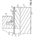
- the plenum cover 66 is formed with slots 68 (Fig. 5) extending perpendicular to the machine direction across substantially the entire width of the wet web 24 to permit passage of pressurized fluid from the air plenum 60 through the fabrics and the wet web.
- the vacuum box 62 is operatively connected to a vacuum source and fixedly mounted to a support structure (not shown).
- the vacuum box 62 comprises a cover 70 having a top surface 72 over which the forming fabric 22 travels.
- the vacuum box cover 70 is formed with a pair of slots 74 (Figs. 3 and 5) that correspond to the location of the slots 68 in the plenum cover 66.
- the pressurized fluid dewaters the wet web 24 as the pressurized fluid is drawn from the air plenum 60 into and through the vacuum box 62.
- the fluid pressure within the air plenum 60 is desirably maintained at about 5 pounds per square inch (psi) (0.35 bar) or greater, and particularly within the range of from about 5 to about 30 psi (0.35 - 2.07 bar), such as about 15 psi (1.03 bar).
- the fluid pressure within the air plenum 60 is desirably monitored and controlled to a predetermined level.
- the bottom surface 67 of the plenum cover 66 is desirably gently curved to facilitate web control.
- the surface 67 is curved toward the vacuum box 62, that is curved about an axis disposed on the vacuum box side of the web 24.
- the curvature of the bottom surface 67 allows a change in angle of the combination of the supporting fabric 32, the wet web 24, and the forming fabric 22 resulting in a net downward force that seals the vacuum box 62 against the entry of outside air and supports the wet web 24 during the dewatering process.
- the angle of curvature allows the loading and unloading of the air press 30 as required from time to time, based on process conditions.
- the change in angle necessary is dependent on the pressure differential between the pressure and vacuum sides and is desirably above 5 degrees, and particularly within the range of 5 to 30 degrees, typically about 7.5 degrees.
- the top and bottom surfaces 72 and 67 desirably have differing radii of curvature.
- the radius of curvature of the bottom surface 67 is desirably larger than the radius of curvature of the top surface 72 so as to form contact lines between the air plenum 60 and the vacuum box 62 at the leading and trailing edges 76 of the air press 30.
- the leading and trailing edges of the air press 30 may also be provided with end seals 78 (Fig. 3) that are maintained in very close proximity to or contact with the support fabric 32 at all times.
- the end seals 78 minimize the escape of pressurized fluid between the air plenum 60 and the vacuum box 62 in the machine direction.
- Suitable end seals 78 may be formed of resilient plastic compounds or the like.
- the air press 30 is desirably provided with side seal members 80 to prevent the loss of pressurized fluid along the side edges 82 of the air press.
- the side seal members 80 comprise a semi-rigid material that is adapted to deform or flex slightly when exposed to the pressurized fluid of the air plenum 60.
- the illustrated side seal members 80 define a slot 84 for attachment to the vacuum box cover 70 using a clamping bar 85 and fastener 86 or other suitable means.
- each side seal member 80 is L-shaped with a leg 88 projecting upward from the vacuum box cover 70 into a side seal slot 89 formed in the plenum cover 66.
- Pressurized fluid from the air plenum 60 causes the legs 88 to bend outward into sealing contact with the outward surface of the side seal slot 89 of the plenum cover 66, as shown in Figs. 4 and 5.
- the position of the side seal members 80 could be reversed, such that they are fixedly attached to the plenum cover 66 and make sealing contact with contact surfaces defined by the vacuum box cover 70 (not shown). In any such alternative designs, it is desirable for the side seal member to be urged into engagement with the sealing contact surface by the pressurized fluid.
- a position control mechanism 90 maintains the air plenum 60 in close proximity to the vacuum box 62 and in contact with the support fabric 32.
- the position control mechanism 90 comprises a pair of levers 92 connected by crosspieces 93 and fixedly attached to the air plenum 60 by suitable fasteners 94 (Fig. 3). The ends of the levers 92 opposite the air plenum 60 are rotatably mounted on a shaft 96.
- the position control mechanism 90 also comprises a counterbalance cylinder 98 operably connecting a fixed structural support 99 and one of the crosspieces 93.
- the counterbalance cylinder 98 is adapted to extend or retract and thereby cause the levers 92 to rotate about the shaft 96, which causes the air plenum 60 to move closer to or further from the vacuum box 62.
- a control system causes the counterbalance cylinder 98 to extend sufficiently for the end seals 78 to contact the support fabric 32 and the side seal members 80 to be positioned within the side seal slots 89.
- the air press 30 is activated such that pressurized fluid fills the air plenum 60 and the semi-rigid side seal members 80 are forced into sealing engagement with the plenum cover 66.
- the pressurized fluid also creates an upward force tending to move the air plenum 60 away from the support fabric 32.
- the control system directs operation of the counterbalance cylinder 98 to offset this upward force based on continuous measurements of the fluid pressure within the air plenum 60 by the pressure monitoring system.
- the end seals 78 are thereby maintained in very close proximity to or contact with the support fabric 32 at all times.
- the control system counters random pressure drops or peaks within the air plenum 60 by proportionately decreasing or increasing the force applied by the counterbalance cylinder 98. Consequently, the end seals 78 do not clamp the fabrics 32 and 22, which would otherwise lead to excessive wear of the fabrics.
- FIG. 6 An alternative sealing system for the air press 30 is representatively shown in Fig. 6.
- the air plenum 100 is provided with a pivotable arm 102 defining or carrying a sealing bar 104 that is adapted to ride on the support fabric 32 across the width of the wet web 24 to minimize escape of pressurized fluid in the machine direction. While only one arm 102 is illustrated in Fig. 6, it should be understood that a second arm at the opposite end of the air plenum 100 may be employed and constructed in a similar manner.
- the sides of the air plenum 100 may incorporate side seal members 80 as described in relation to Figs. 2 - 5 or be fixedly mounted on the vacuum box 62 to minimize or eliminate side leakage of pressurized fluid.
- the pivotable arm 102 desirably comprises a rigid material such as structural steel, graphite composites, or the like.
- the arm 102 has a first portion 106 disposed at least partially inside the air plenum 100 and a second portion 108 preferably disposed outside the air plenum.
- the arm 102 is pivotally mounted on the air plenum 100 by a hinge 110.
- a hinge seal 112 impervious to the pressurized fluid is attached to both the interior surface of a wall 114 of the air plenum 100 and the first portion 106 to prevent escape of the pressurized fluid.
- the sealing bar 104 is desirably a separate element mounted on the first portion 106 and motivated toward the support fabric 32 (not shown in Fig. 6) by contact of the pressurized fluid on the first portion.
- Suitable sealing bars 104 may be formed of a low-resistance, low friction coefficient, durable material such as ceramic, heat resistant polymers, or the like.
- a counterbalance bladder 120 having an inflatable chamber 122 is mounted on the second portion 108 of the arm 102 with brackets 124 or other suitable means.
- the chamber 122 is operably connected to a source of pressurized fluid such as air to inflate the chamber.
- the arm 102 and the bladder 120 are positioned so that the bladder when inflated (not shown) presses against the exterior surface of the wall 114 of the air plenum 100 causing the arm to pivot about the hinge 110.
- a mechanism using pressurized cylinders could be used in place of the counterbalance bladder as a means for pivoting the arm 102.
- a control system is operable to inflate or deflate the bladder 120 proportionally in response to the pressure of the fluid within the air plenum 100. For example, as pressure within the air plenum 100 increases, the control system is adapted to increase pressure within or inflation of the counterbalance bladder 120 so that the sealing bar 104 does not clamp down excessively against the support fabric 32.
- the design of the vacuum transfer shoe 37 used in the transfer fabric section of the process (Fig. 1) is more clearly illustrated in Figs. 7 and 8.
- the vacuum transfer shoe 37 defines a vacuum slot 130 (Fig. 7) connected to a source of vacuum and having a length of "L" which is suitably from about 0.5 to about 1 inch (12.7 - 25.4 mm).
- a suitable vacuum slot length is about 1 inch (25.4 mm).
- the vacuum slot 130 has a leading edge 132 and a trailing edge 133, forming corresponding incoming and outgoing land areas 134 and 135 of the vacuum transfer shoe 37.
- the trailing edge 133 of the vacuum slot 130 is recessed relative to the leading edge 132, which is caused by the different orientation of the outgoing land area 135 relative to that of the incoming land area 134.
- the angle "A" between the planes of the incoming land area 134 and the outgoing land area 135 can be about 0.5 degrees or greater, more specifically about 1 degree or greater, and still more specifically about 5 degrees or greater in order to provide sufficient separation of the forming fabric 22 and the transfer fabric 36 as they are converging and diverging.
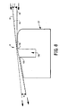
- Fig. 8 further illustrates the wet tissue web 24 traveling in the direction shown by the arrows toward the vacuum transfer shoe 37. Also approaching the vacuum transfer shoe 37 is the transfer fabric 36 traveling at a slower speed.
- the angle of convergence between the two incoming fabrics is designated as "C”.
- the angle of divergence between the two fabrics is designated as "D”.
- the two fabrics simultaneously converge and diverge at point "P", which corresponds to the leading edge 132 of the vacuum slot 130. It is not necessary or desirable that the web be in contact with both fabrics over the entire length of the vacuum slot 130 to effect the transfer from the forming fabric 22 to the transfer fabric 36.
- neither the forming fabric 22 nor the transfer fabric 36 need to be deflected more than a small amount to carry out the transfer, which can reduce fabric wear. Numerically, the change in direction of either fabric can be less than 5 degrees.
- the transfer fabric 36 is traveling at a slower speed than the forming fabric 22. If more than one transfer fabric is used, the speed differential between fabrics can be the same or different. Multiple transfer fabrics can provide operational flexibility as well as a wide variety of fabric/speed combinations to influence the properties of the final product.
- the level of vacuum used for the differential speed transfers can be from about 76 to about 381 mm (about 3 to about 15 inches) of mercury, preferably about 127 mm (about 5 inches) of mercury.
- the vacuum shoe (negative pressure) can be supplemented or replaced by the use of positive pressure from the opposite side of the web 24 to blow the web onto the next fabric in addition to or as a replacement for sucking it onto the next fabric with vacuum.
- a vacuum roll or rolls can be used to replace the vacuum shoe(s).
- MD Tensile strength, MD Stretch, and CD Tensile strength are obtained according to TAPPI Test Method 494 OM-88 "Tensile Breaking Properties of Paper and Paperboard" using the following parameters: Crosshead speed is 10.0 in/min (254 mm/min); full scale load is 10 lb (4,540 g); jaw span (the distance between the jaws, sometimes referred to as the gauge length) is 2.0 inches (50.8 mm); and specimen width is 3 inches (76.2 mm).
- the tensile testing machine is a Sintech, Model CITS-2000 from Systems Integration Technology Inc., Stoughton, Massachusetts, a division of MTS Systems Corporation, Research Triangle Park, North Carolina.
- the stiffness of the Example sheets can be objectively represented by either the maximum slope of the machine direction (MD) load/elongation curve for the tissue (hereinafter referred to as the "MD Slope") or by the machine direction Stiffness (herein defined), which further takes into account the caliper of the tissue and the number of plies of the product. Determining the MD Slope will be hereinafter described in connection with Figure 9.
- the MD Slope is the maximum slope of the machine direction load/elongation curve for the tissue.
- the units for the MD Slope are kilograms per 3 inches (7.62 centimeters).
- the MD Stiffness is calculated by multiplying the MD Slope by the square root of the quotient of the Caliper divided by the number of plies.
- the units of the MD Stiffness are (kilograms per 7.62 cm) - micrometer 0.5 ((kilograms per 3 inches) -microns 0.5 ).
- Figure 9 is a generalized load/elongation curve for a tissue sheet, illustrating the determination of the MD Slope.
- the tensile tester is programmed (GAP [General Applications Program], version 2.5, Systems Integration Technology Inc., Stoughton, MA; a division of MTS Systems Corporation, Research Triangle Park, NC) such that it calculates a linear regression for the points that are sampled from P1 to P2. This calculation is done repeatedly over the curve by adjusting the points P1 and P2 in a regular fashion along the curve (hereinafter described). The highest value of these calculations is the Max Slope and, when performed on the machine direction of the specimen, will be referred to herein as the MD Slope.
- the tensile tester program should be set up such that five hundred points such as P1 and P2 are taken over a two and one-half inch (63.5 mm) span of elongation. This provides a sufficient number of points to exceed essentially any practical.elongation of the specimen. With a ten inch per minute (254 mm/min) crosshead speed, this translates into a point every 0.030 seconds.
- the program calculates slopes among these points by setting the 10th point as the initial point (for example P1), counting thirty points to the 40th point (for example, P2) and performing a linear regression on those thirty points. It stores the slope from this regression in an array.
- the program then counts up ten points to the 20th point (which becomes P1) and repeats the procedure again (counting thirty points to what would be the 50th point (which becomes P2), calculating that slope and also storing it in the array). This process continues for the entire elongation of the sheet.
- the Max Slope is then chosen as the highest value from this array.
- the units of Max Slope are kg per three-inch specimen width. (Strain is, of course, dimensionless since the length of elongation is divided by the length of the jaw span. This calculation is taken into account by the testing machine program.)
- Example 1 - 4 a number of uncreped throughdried tissues were produced using the method substantially as illustrated in Fig. 1. More specifically, Examples 1 - 4 were all three-layered, single-ply bath tissues in which the outer layers comprised disperged, debonded eucalyptus fibers and the center layer comprised refined northern softwood kraft fibers. Cenebra eucalyptus fibers were pulped for 15 minutes at 10% consistency and dewatered to 30% consistency. The pulp was then fed to a Maule shaft disperger. The disperger was operated at 160° F. (70° C.) with a power input of 2.2 HPD/T (1.8 kilowatt-days per tonne). Subsequent to disperging, a softening agent (Witco C6027) was added to the pulp in the amount of 7.5 kg per metric ton dry fiber (0.75 weight percent).
- a softening agent Wico C6027
- the softwood fibers Prior to formation, the softwood fibers were pulped for 30 minutes at 3.2 percent consistency, while the disperged, debonded eucalyptus fibers were diluted to 2.5 percent consistency.
- the overall layered sheet weight was split 35%/30%/35% for Examples 1, 2 and 4 and 33%/34%/33% for Example 3 among the disperged eucalyptus/refined softwood/disperged eucalyptus layers.
- the center layer was refined to levels required to achieve target strength values, while the outer layers provided softness and bulk. For added dry and temporary wet strength, a strength agent identified as Parez 631 NC was added to the center layer.
- the resulting three-layered sheet was formed on a twin-wire, suction form roll, former with forming fabrics being Appleton Mills 2164-B fabrics.
- Speed of the forming fabric ranged between 11.8 and 12.3 meters per second.
- the newly-formed web was then dewatered to a consistency of 25 - 26% using vacuum suction from below the forming fabric without air press, and 32 - 33% with air press before being transferred to the transfer fabric which was traveling at 9.1 meters per second (29 - 35% rush transfer).
- the transfer fabric was Appleton Mills 2164-B.
- a vacuum shoe pulling about 6 - 15 inches (150 - 380 millimeters) of mercury vacuum was used to transfer the web to the transfer fabric.
- the web was then transferred to a throughdrying fabric traveling at a speed of about 9.1 meters per second. Appleton Mills T124-4 and T124-7 throughdrying fabrics were used. The web was carried over a Honeycomb throughdryer operating at a temperature of about 350° F. (175° C.) and dried to a final dryness of about 94 - 98% consistency.
- the sequence of producing the Example sheets was as follows: Four rolls of the Example 1 sheets were produced. The consistency data reported in Table 1 is based on 2 measurements, one at the beginning and one at the end of the 4 rolls. The other data shown in Table 1 represents an average based on 4 measurements, one per roll.
- the air press was then turned on. Data just prior to and just after activation of the air press is shown in Table 3 (individual data points). This data shows that the air press caused significant increases in tensile values. The process was then modified to decrease the tensile values to levels comparable to the Example 1 sheets. After this process adjustment period, four rolls of the Example 2 sheets (this invention) were produced. Later, 4 rolls of the Example 3 sheets (this invention) were produced using a different throughdrying fabric and with the air press activated.
- Example 4 The air press was shut off and the process adjusted to regain tensile strength values comparable to the Example 3 sheets. Four rolls of Example 4 sheets were then produced.
- the consistency data for each Example in Table 2 is an average based on 2 measurements, one at the beginning and one at the end of each set of 4 rolls.
- the other data in Table 2 is based on an average of 4 measurements per Example sheet, one per roll.
- Table 2 the Example 4 data is presented in the left column and the Example 3 data is presented in the right column to remain consistent with Tables 1 and 3, which show data without the air press in the left column and data with the air press in the right column.
- EXAMPLE 1 EXAMPLE 2 (No Air Press) (With Air Press and Process Adjustment) Consistency @ Rush Transfer (%) 25.2 - 26.1 32.5 - 33.4 MD Tensile ((grams/3")) (grams/7.62cm) 933 944 CD Tensile ((grams/3")) (grams/7.62cm) 676 662 MD Stretch (%) 24.5 24.7 MD Slope ((kg/3")) (kg/7.62cm) 4.994 3.778 Caliper (micrometer) 671 607 MD Stiffness ((kg/3"-microns 0.5 )) (kg/7.62 cm - micrometer 0.5 ) 129 93 Basis Weight (gsm) 34.6 35.2 TAD Fabric T-124-4 T-124-4 Refiner (kW) 32 26 Rush (%) 32 29 HW/SW (%) 70/30 70/30 Parez (kg/mt) 4.0 3.2 EXAMPLE 4 EXAMPLE 3 (No Air Press) (With Air Press and Process Adjustment) Consist
- the air press produces significantly higher consistencies upstream of the differential speed transfer which result in smoother sheets as evidenced by lower modulus values.
- the modulus (MD Stiffness) of tissue products is at least 20 percent less than that of a comparable tissue product made without supplementally dewatering to a consistency of greater than about 30 percent.
- the machine direction tensile of the tissue products is at least 20 percent greater, and the cross direction tensile of the tissue products is at least 20 percent greater, than that of a comparable tissue product made without supplementally dewatering to a consistency of greater than about 30 percent.
- the machine direction stretch of tissue products is at least 17 percent greater than that of a comparable tissue product made without supplementally dewatering to a consistency of greater than about 30 percent.
Claims (26)
- Verfahren zum Herstellen eines weichen Tissue-Bogens, umfassend die folgenden Schritte:dadurch gekennzeichnet, dass die nasse Bahn (24) zusätzlich unter Verwendung eines nichtkomprimierenden Entwässerungsmittels bis zu einer Konsistenz von mehr als 30 Prozent entwässert wird, bevor sie auf den Transferstoff (36) transferiert wird.Aufbringen einer wässrigen Suspension von Fasern zur Papierherstellung auf einen Endlosformierstoff (22), um eine nasse Bahn (24) zu bilden;Entwässern der nassen Bahn (24) bis zu einer Konsistenz von 20 bis 30 Prozent;Transferieren der Bahn auf einen Transferstoff (36), welcher sich mit einer Geschwindigkeit bewegt, welche 10 bis 80 Prozent geringer ist als die des Formierstoffs (22);Transferieren der Bahn (24) auf einen Durchlufttrocknungsstoff (40); undDurchlufttrocknen der Bahn bis zu einer endgültigen Trockenheit,
- Verfahren nach Anspruch 1, wobei das nichtkomprimierende Entwässerungsmittel ausgewählt ist aus der Gruppe bestehend aus einer Luftpresse (30), Infrarottrocknung, Mikrowellentrocknung, Ultraschalltrocknung, Durchlufttrocknung, und Verdrängungsentwässerung.
- Verfahren nach Anspruch 1, wobei das nichtkomprimierende Entwässerungsmittel eine Luftpresse (30) umfasst.
- Verfahren nach Anspruch 3, wobei die Luftpresse (30) die Konsistenz der nassen Bahn (24) um wenigstens 3 Prozent erhöht.
- Verfahren nach einem der Ansprüche 3 oder 4, wobei die Luftpresse (30) eine Luftplenumkammer (60) umfasst, und Fluiddruck innerhalb der Luftplenumkammer (60) innerhalb des Bereichs von 34 bis 207 kPa (5 bis 30 Pfund pro Quadratzoll) gehalten wird.
- Verfahren nach einem der Ansprüche 3 bis 5, wobei die Luftpresse (30) eine Druckdifferenz über die nasse Bahn von 889 bis 1524 mm (35 bis 60 Zoll) Quecksilber bereitstellt.
- Verfahren nach einem der Ansprüche 3 bis 6, wobei die Luftpresse (30) die nasse Bahn (24) bis zu einer Konsistenz von mehr als 31 Prozent entwässert.
- Verfahren nach Anspruch 7, wobei die Luftpresse (30) die nasse Bahn (24) bis zu einer Konsistenz von mehr als 32 Prozent entwässert.
- Verfahren nach einem der Ansprüche 3 bis 6, wobei die Luftpresse (30) die nasse Bahn (24) bis zu einer Konsistenz von 31 bis 36 Prozent entwässert.
- Verfahren nach einem der Ansprüche 3 bis 9, wobei die nasse Bahn (24) zwischen dem Formierstoff (22) und einem Stützstoff (32) eingebettet ist, wenn sie durch die Luftpresse (30) transportiert wird.
- Verfahren nach einem der vorangehenden Ansprüche, wobei Entwässern der nassen Bahn (24) bis zu einer Konsistenz von 20 bis 30 Prozent unter Verwendung von mehreren Vakuumkästen (62) durchgeführt wird.
- Verfahren nach einem der vorangehenden Ansprüche, wobei der Formierstoff (22) sich mit einer Geschwindigkeit von wenigstens 10 m/s (2000 Fuß pro Minute) bewegt.
- Tissue-Produkt, erhältlich mit Hilfe des Verfahrens nach einem der vorangehenden Ansprüche, wobei die Steifigkeit des Tissue-Produkts in Maschinenrichtung wenigstens 20 Prozent geringer ist als die eines identischen Tissue-Produkts, welchem es an der zusätzlichen Entwässerungsbehandlung bis zu einer Konsistenz von mehr als 30 Prozent fehlt.
- Tissue-Produkt nach Anspruch 13, wobei die Reißfestigkeit des Tissue-Produkts in Maschinenrichtung wenigstens 20 Prozent höher ist als die eines identischen Tissue-Produkts, welchem es an der zusätzlichen Entwässerungsbehandlung bis zu einer Konsistenz von mehr als 30 Prozent fehlt.
- Tissue-Produkt nach einem der Ansprüche 13 oder 14, wobei die Reißfestigkeit des Tissue-Produkts in der Maschinenquerrichtung wenigstens 20 Prozent höher ist als die eines identischen Tissue-Produkts, welchem es an der zusätzlichen Entwässerungsbehandlung bis zu einer Konsistenz von mehr als 30 Prozent fehlt.
- Tissue-Produkt nach einem der Ansprüche 13 bis 15, wobei die Dehnung des Tissue-Produkts in Maschinenrichtung wenigstens 17 Prozent höher ist als die eines identischen Tissue-Produkts, welchem es an der zusätzlichen Entwässerungsbehandlung bis zu einer Konsistenz von mehr als 30 Prozent fehlt.
- Luftpresse (30) zum Entwässern einer nassen Bahn (24), umfassend:eine Luftplenumkammer (60), umfassend eine Plenumkammerabdeckung (66) mit einer unteren Oberfläche (67);ein Mittel zum Zuführen von unter Druck stehendem Fluid zu der Luftplenumkammer (60);einen Vakuumkasten (62), umfassend eine Vakuumkastenabdeckung (70) mit einer oberen Oberfläche (72), die in nächster Nähe zur unteren Oberfläche (67) der Plenumkammerabdeckung (66) angeordnet ist;ein Mittel zum Anlegen von Vakuum an den Vakuumkasten; undSeitendichtungselemente (80), welche eingerichtet sind, um mit der Luftplenumkammer (60) und dem Vakuumkasten (62) in Kontakt zu stehen, um Entweichen des unter Druck stehenden Fluids zu minimieren, wobei die Seitendichtungselemente (80) an einem von der Luftplenumkammer (60) und dem Vakuumkasten (62) angebracht sind und in nächster Nähe zu Seitendichtungskontaktoberflächen positioniert sind, welche durch den jeweils anderen von der Luftplenumkammer (60) und dem Vakuumkasten (62) definiert sind; wobei die Seitendichtungselemente (80) eingerichtet sind, sich in dichtenden Kontakt mit der Seitendichtungskontaktoberfläche zu biegen, wenn sie unter Druck stehendem Fluid ausgesetzt werden.
- Luftpresse nach Anspruch 17, wobei die Seitendichtungselemente (80) an der Vakuumkastenabdeckung (70) angebracht sind, und die Plenumkammerabdeckung (66) Dichtungsschlitze und die Seitendichtungskontaktoberflächen definiert.
- Luftpresse nach Anspruch 17, ferner umfassend Enddichtungen (78), welche an der Plenumkammerabdeckung (66) angebracht sind.
- Luftpresse nach einem der Ansprüche 17 oder 19, ferner umfassend einen Positionssteuermechanismus (90), welcher eingerichtet ist, um die Luftplenumkammer (60) in nächster Nähe zu dem Vakuumkasten (62) zu halten.
- Luftpresse nach Anspruch 20, wobei der Positionssteuermechanismus (90) einen drehbar befestigten Hebel (92) umfasst, welcher an der Luftplenumkammer (60) angebracht ist, und einen Gegengewichtszylinder (98) umfasst, welcher eingerichtet ist, um den Hebel (92) zu drehen.
- Luftpresse nach Anspruch 20, ferner umfassend ein Steuersystem, welches eingerichtet ist, um einen Betrieb des Gegengewichtszylinders (98) in Reaktion auf Messungen von Fluiddruck innerhalb der Luftplenumkammer (60) zu leiten.
- Luftpresse nach Anspruch 17, 18 oder 19, wobei die obere und untere Oberfläche zu dem Vakuumkasten (62) hin gekrümmt sind.
- Luftpresse nach Anspruch 23, wobei die obere (72) und untere Oberfläche (67) verschiedene Krümmungsradien aufweisen.
- Luftpresse nach Anspruch 17, umfassend:einen Arm (102), welcher schwenkbar an der Luftplenumkammer (100) befestigt ist und einen ersten (106) und einen zweiten (108) Abschnitt umfasst, wobei der erste Abschnitt (106) wenigstens teilweise im Innern der Luftplenumkammer (100) angeordnet ist und einen Dichtungsstab (104) umfasst; undein Mittel zum Schwenken des Arms (102) in Reaktion auf Fluiddruck innerhalb der Luftplenumkammer (100).
- Luftpresse nach Anspruch 25, ferner umfassend eine Gelenksdichtung (112), welche für unter Druck stehendes Fluid undurchlässig ist und sowohl an der Luftplenumkammer (100) als auch dem ersten Abschnitt (106) angebracht ist.
Applications Claiming Priority (3)
| Application Number | Priority Date | Filing Date | Title |
|---|---|---|---|
| US64750896A | 1996-05-14 | 1996-05-14 | |
| US647508 | 1996-05-14 | ||
| PCT/US1997/006894 WO1997043484A1 (en) | 1996-05-14 | 1997-04-25 | Method and apparatus for making soft tissue |
Publications (2)
| Publication Number | Publication Date |
|---|---|
| EP0907797A1 EP0907797A1 (de) | 1999-04-14 |
| EP0907797B1 true EP0907797B1 (de) | 2005-12-28 |
Family
ID=24597257
Family Applications (1)
| Application Number | Title | Priority Date | Filing Date |
|---|---|---|---|
| EP97924516A Expired - Lifetime EP0907797B1 (de) | 1996-05-14 | 1997-04-25 | Verfahren und vorrichtung zur herstellung von weichem tissuepapier |
Country Status (11)
| Country | Link |
|---|---|
| EP (1) | EP0907797B1 (de) |
| AR (2) | AR007080A1 (de) |
| AU (1) | AU710298B2 (de) |
| BR (1) | BR9709083A (de) |
| CA (1) | CA2252695A1 (de) |
| CO (1) | CO5031318A1 (de) |
| DE (1) | DE69734980T2 (de) |
| SV (1) | SV1997000039A (de) |
| TW (1) | TW403802B (de) |
| WO (1) | WO1997043484A1 (de) |
| ZA (1) | ZA974113B (de) |
Families Citing this family (15)
| Publication number | Priority date | Publication date | Assignee | Title |
|---|---|---|---|---|
| US6096169A (en) * | 1996-05-14 | 2000-08-01 | Kimberly-Clark Worldwide, Inc. | Method for making cellulosic web with reduced energy input |
| US6149767A (en) * | 1997-10-31 | 2000-11-21 | Kimberly-Clark Worldwide, Inc. | Method for making soft tissue |
| AU739501B2 (en) * | 1996-05-14 | 2001-10-11 | Kimberly-Clark Worldwide, Inc. | Method for making soft tissue |
| US6083346A (en) * | 1996-05-14 | 2000-07-04 | Kimberly-Clark Worldwide, Inc. | Method of dewatering wet web using an integrally sealed air press |
| TW527482B (en) * | 1997-10-31 | 2003-04-11 | Kimberly Clark Co | Air press for dewatering wet web |
| US6506287B1 (en) | 1998-03-16 | 2003-01-14 | Applied Materials, Inc. | Overlap design of one-turn coil |
| US6280573B1 (en) | 1998-08-12 | 2001-08-28 | Kimberly-Clark Worldwide, Inc. | Leakage control system for treatment of moving webs |
| CO5021169A1 (es) * | 1998-11-30 | 2001-03-27 | Kimberly Clark Co | Aparato y metodo para dernar una tira de papel |
| US6454904B1 (en) | 2000-06-30 | 2002-09-24 | Kimberly-Clark Worldwide, Inc. | Method for making tissue sheets on a modified conventional crescent-former tissue machine |
| US6497789B1 (en) | 2000-06-30 | 2002-12-24 | Kimberly-Clark Worldwide, Inc. | Method for making tissue sheets on a modified conventional wet-pressed machine |
| US7494563B2 (en) | 2002-10-07 | 2009-02-24 | Georgia-Pacific Consumer Products Lp | Fabric creped absorbent sheet with variable local basis weight |
| US8603296B2 (en) | 2002-10-07 | 2013-12-10 | Georgia-Pacific Consumer Products Lp | Method of making a fabric-creped absorbent cellulosic sheet with improved dispensing characteristics |
| US7789995B2 (en) * | 2002-10-07 | 2010-09-07 | Georgia-Pacific Consumer Products, LP | Fabric crepe/draw process for producing absorbent sheet |
| US8293072B2 (en) | 2009-01-28 | 2012-10-23 | Georgia-Pacific Consumer Products Lp | Belt-creped, variable local basis weight absorbent sheet prepared with perforated polymeric belt |
| US8540846B2 (en) | 2009-01-28 | 2013-09-24 | Georgia-Pacific Consumer Products Lp | Belt-creped, variable local basis weight multi-ply sheet with cellulose microfiber prepared with perforated polymeric belt |
Family Cites Families (5)
| Publication number | Priority date | Publication date | Assignee | Title |
|---|---|---|---|---|
| US4440597A (en) * | 1982-03-15 | 1984-04-03 | The Procter & Gamble Company | Wet-microcontracted paper and concomitant process |
| US5048589A (en) * | 1988-05-18 | 1991-09-17 | Kimberly-Clark Corporation | Non-creped hand or wiper towel |
| US5149401A (en) * | 1990-03-02 | 1992-09-22 | Thermo Electron Web Systems, Inc. | Simultaneously controlled steam shower and vacuum apparatus and method of using same |
| TW250512B (de) * | 1992-05-15 | 1995-07-01 | Beloit Technologies Inc | |
| US5607551A (en) * | 1993-06-24 | 1997-03-04 | Kimberly-Clark Corporation | Soft tissue |
-
1997
- 1997-04-25 DE DE69734980T patent/DE69734980T2/de not_active Expired - Lifetime
- 1997-04-25 AU AU29919/97A patent/AU710298B2/en not_active Ceased
- 1997-04-25 CA CA002252695A patent/CA2252695A1/en not_active Abandoned
- 1997-04-25 BR BR9709083A patent/BR9709083A/pt not_active IP Right Cessation
- 1997-04-25 WO PCT/US1997/006894 patent/WO1997043484A1/en active IP Right Grant
- 1997-04-25 EP EP97924516A patent/EP0907797B1/de not_active Expired - Lifetime
- 1997-05-13 ZA ZA9704113A patent/ZA974113B/xx unknown
- 1997-05-13 CO CO97025516A patent/CO5031318A1/es unknown
- 1997-05-13 SV SV1997000039A patent/SV1997000039A/es unknown
- 1997-06-02 TW TW086107515A patent/TW403802B/zh not_active IP Right Cessation
- 1997-09-05 AR ARP970101957A patent/AR007080A1/es unknown
-
1998
- 1998-05-05 AR ARP980102093A patent/AR012662A2/es unknown
Also Published As
| Publication number | Publication date |
|---|---|
| AU2991997A (en) | 1997-12-05 |
| AR007080A1 (es) | 1999-10-13 |
| ZA974113B (en) | 1997-12-09 |
| CO5031318A1 (es) | 2001-04-27 |
| EP0907797A1 (de) | 1999-04-14 |
| TW403802B (en) | 2000-09-01 |
| AU710298B2 (en) | 1999-09-16 |
| WO1997043484A1 (en) | 1997-11-20 |
| AR012662A2 (es) | 2000-11-08 |
| SV1997000039A (es) | 1998-04-20 |
| CA2252695A1 (en) | 1997-11-20 |
| BR9709083A (pt) | 1999-08-03 |
| DE69734980T2 (de) | 2006-09-21 |
| DE69734980D1 (de) | 2006-02-02 |
Similar Documents
| Publication | Publication Date | Title |
|---|---|---|
| US6149767A (en) | Method for making soft tissue | |
| US6093284A (en) | Air press for dewatering a wet web with pivotable arm seal | |
| US6306257B1 (en) | Air press for dewatering a wet web | |
| US5667636A (en) | Method for making smooth uncreped throughdried sheets | |
| JP3748884B2 (ja) | ソフトティッシュ | |
| US6077398A (en) | Method and apparatus for wet web molding and drying | |
| EP0907797B1 (de) | Verfahren und vorrichtung zur herstellung von weichem tissuepapier | |
| EP1295986B1 (de) | Verfahren zur Entwässerung einer nassen Bahn mit einer Luftpresse | |
| AU739501B2 (en) | Method for making soft tissue | |
| KR100481105B1 (ko) | 소프트티슈를제조하기위한방법및장치 | |
| MXPA98008930A (en) | Method and apparatus to manufacture tisu su |
Legal Events
| Date | Code | Title | Description |
|---|---|---|---|
| PUAI | Public reference made under article 153(3) epc to a published international application that has entered the european phase |
Free format text: ORIGINAL CODE: 0009012 |
|
| 17P | Request for examination filed |
Effective date: 19981027 |
|
| AK | Designated contracting states |
Kind code of ref document: A1 Designated state(s): BE DE ES FR GB IT NL PT SE |
|
| 17Q | First examination report despatched |
Effective date: 20040216 |
|
| GRAP | Despatch of communication of intention to grant a patent |
Free format text: ORIGINAL CODE: EPIDOSNIGR1 |
|
| GRAS | Grant fee paid |
Free format text: ORIGINAL CODE: EPIDOSNIGR3 |
|
| GRAA | (expected) grant |
Free format text: ORIGINAL CODE: 0009210 |
|
| AK | Designated contracting states |
Kind code of ref document: B1 Designated state(s): BE DE ES FR GB IT NL PT SE |
|
| PG25 | Lapsed in a contracting state [announced via postgrant information from national office to epo] |
Ref country code: NL Free format text: LAPSE BECAUSE OF FAILURE TO SUBMIT A TRANSLATION OF THE DESCRIPTION OR TO PAY THE FEE WITHIN THE PRESCRIBED TIME-LIMIT Effective date: 20051228 |
|
| REG | Reference to a national code |
Ref country code: GB Ref legal event code: FG4D |
|
| REF | Corresponds to: |
Ref document number: 69734980 Country of ref document: DE Date of ref document: 20060202 Kind code of ref document: P |
|
| PG25 | Lapsed in a contracting state [announced via postgrant information from national office to epo] |
Ref country code: SE Free format text: LAPSE BECAUSE OF FAILURE TO SUBMIT A TRANSLATION OF THE DESCRIPTION OR TO PAY THE FEE WITHIN THE PRESCRIBED TIME-LIMIT Effective date: 20060328 |
|
| PG25 | Lapsed in a contracting state [announced via postgrant information from national office to epo] |
Ref country code: ES Free format text: LAPSE BECAUSE OF FAILURE TO SUBMIT A TRANSLATION OF THE DESCRIPTION OR TO PAY THE FEE WITHIN THE PRESCRIBED TIME-LIMIT Effective date: 20060408 |
|
| PG25 | Lapsed in a contracting state [announced via postgrant information from national office to epo] |
Ref country code: PT Free format text: LAPSE BECAUSE OF FAILURE TO SUBMIT A TRANSLATION OF THE DESCRIPTION OR TO PAY THE FEE WITHIN THE PRESCRIBED TIME-LIMIT Effective date: 20060529 |
|
| NLV1 | Nl: lapsed or annulled due to failure to fulfill the requirements of art. 29p and 29m of the patents act | ||
| ET | Fr: translation filed | ||
| PLBE | No opposition filed within time limit |
Free format text: ORIGINAL CODE: 0009261 |
|
| STAA | Information on the status of an ep patent application or granted ep patent |
Free format text: STATUS: NO OPPOSITION FILED WITHIN TIME LIMIT |
|
| 26N | No opposition filed |
Effective date: 20060929 |
|
| PGFP | Annual fee paid to national office [announced via postgrant information from national office to epo] |
Ref country code: BE Payment date: 20070430 Year of fee payment: 11 |
|
| BERE | Be: lapsed |
Owner name: *KIMBERLY-CLARK WORLDWIDE INC. Effective date: 20080430 |
|
| PG25 | Lapsed in a contracting state [announced via postgrant information from national office to epo] |
Ref country code: BE Free format text: LAPSE BECAUSE OF NON-PAYMENT OF DUE FEES Effective date: 20080430 |
|
| PGFP | Annual fee paid to national office [announced via postgrant information from national office to epo] |
Ref country code: FR Payment date: 20100506 Year of fee payment: 14 |
|
| PGFP | Annual fee paid to national office [announced via postgrant information from national office to epo] |
Ref country code: IT Payment date: 20100428 Year of fee payment: 14 Ref country code: DE Payment date: 20100428 Year of fee payment: 14 |
|
| PGFP | Annual fee paid to national office [announced via postgrant information from national office to epo] |
Ref country code: GB Payment date: 20100401 Year of fee payment: 14 |
|
| REG | Reference to a national code |
Ref country code: DE Ref legal event code: R119 Ref document number: 69734980 Country of ref document: DE |
|
| REG | Reference to a national code |
Ref country code: DE Ref legal event code: R119 Ref document number: 69734980 Country of ref document: DE |
|
| GBPC | Gb: european patent ceased through non-payment of renewal fee |
Effective date: 20110425 |
|
| REG | Reference to a national code |
Ref country code: FR Ref legal event code: ST Effective date: 20111230 |
|
| PG25 | Lapsed in a contracting state [announced via postgrant information from national office to epo] |
Ref country code: FR Free format text: LAPSE BECAUSE OF NON-PAYMENT OF DUE FEES Effective date: 20110502 |
|
| PG25 | Lapsed in a contracting state [announced via postgrant information from national office to epo] |
Ref country code: GB Free format text: LAPSE BECAUSE OF NON-PAYMENT OF DUE FEES Effective date: 20110425 Ref country code: IT Free format text: LAPSE BECAUSE OF NON-PAYMENT OF DUE FEES Effective date: 20110425 |
|
| PG25 | Lapsed in a contracting state [announced via postgrant information from national office to epo] |
Ref country code: DE Free format text: LAPSE BECAUSE OF NON-PAYMENT OF DUE FEES Effective date: 20111031 |