EP0907534B1 - Hydraulic braking system and operating method - Google Patents
Hydraulic braking system and operating method Download PDFInfo
- Publication number
- EP0907534B1 EP0907534B1 EP97927177A EP97927177A EP0907534B1 EP 0907534 B1 EP0907534 B1 EP 0907534B1 EP 97927177 A EP97927177 A EP 97927177A EP 97927177 A EP97927177 A EP 97927177A EP 0907534 B1 EP0907534 B1 EP 0907534B1
- Authority
- EP
- European Patent Office
- Prior art keywords
- pressure
- brake
- pump
- pedal
- valve
- Prior art date
- Legal status (The legal status is an assumption and is not a legal conclusion. Google has not performed a legal analysis and makes no representation as to the accuracy of the status listed.)
- Expired - Lifetime
Links
- 238000011017 operating method Methods 0.000 title 1
- 239000012530 fluid Substances 0.000 claims description 6
- 230000033001 locomotion Effects 0.000 claims description 6
- 238000000034 method Methods 0.000 claims description 6
- 230000008569 process Effects 0.000 claims description 5
- 230000006835 compression Effects 0.000 abstract 2
- 238000007906 compression Methods 0.000 abstract 2
- 238000002955 isolation Methods 0.000 description 4
- 238000010586 diagram Methods 0.000 description 3
- 238000006073 displacement reaction Methods 0.000 description 3
- 230000008901 benefit Effects 0.000 description 2
- 230000000903 blocking effect Effects 0.000 description 2
- 238000010276 construction Methods 0.000 description 2
- 230000006735 deficit Effects 0.000 description 2
- 230000000694 effects Effects 0.000 description 2
- 230000002787 reinforcement Effects 0.000 description 2
- 238000011144 upstream manufacturing Methods 0.000 description 2
- 230000004913 activation Effects 0.000 description 1
- 238000002485 combustion reaction Methods 0.000 description 1
- 238000013016 damping Methods 0.000 description 1
- 230000009849 deactivation Effects 0.000 description 1
- 238000007667 floating Methods 0.000 description 1
- 230000036316 preload Effects 0.000 description 1
- 230000009467 reduction Effects 0.000 description 1
- 230000004044 response Effects 0.000 description 1
- 238000006798 ring closing metathesis reaction Methods 0.000 description 1
- 238000007789 sealing Methods 0.000 description 1
Images
Classifications
-
- B—PERFORMING OPERATIONS; TRANSPORTING
- B60—VEHICLES IN GENERAL
- B60T—VEHICLE BRAKE CONTROL SYSTEMS OR PARTS THEREOF; BRAKE CONTROL SYSTEMS OR PARTS THEREOF, IN GENERAL; ARRANGEMENT OF BRAKING ELEMENTS ON VEHICLES IN GENERAL; PORTABLE DEVICES FOR PREVENTING UNWANTED MOVEMENT OF VEHICLES; VEHICLE MODIFICATIONS TO FACILITATE COOLING OF BRAKES
- B60T8/00—Arrangements for adjusting wheel-braking force to meet varying vehicular or ground-surface conditions, e.g. limiting or varying distribution of braking force
- B60T8/32—Arrangements for adjusting wheel-braking force to meet varying vehicular or ground-surface conditions, e.g. limiting or varying distribution of braking force responsive to a speed condition, e.g. acceleration or deceleration
- B60T8/34—Arrangements for adjusting wheel-braking force to meet varying vehicular or ground-surface conditions, e.g. limiting or varying distribution of braking force responsive to a speed condition, e.g. acceleration or deceleration having a fluid pressure regulator responsive to a speed condition
- B60T8/44—Arrangements for adjusting wheel-braking force to meet varying vehicular or ground-surface conditions, e.g. limiting or varying distribution of braking force responsive to a speed condition, e.g. acceleration or deceleration having a fluid pressure regulator responsive to a speed condition co-operating with a power-assist booster means associated with a master cylinder for controlling the release and reapplication of brake pressure through an interaction with the power assist device, i.e. open systems
- B60T8/441—Arrangements for adjusting wheel-braking force to meet varying vehicular or ground-surface conditions, e.g. limiting or varying distribution of braking force responsive to a speed condition, e.g. acceleration or deceleration having a fluid pressure regulator responsive to a speed condition co-operating with a power-assist booster means associated with a master cylinder for controlling the release and reapplication of brake pressure through an interaction with the power assist device, i.e. open systems using hydraulic boosters
- B60T8/442—Arrangements for adjusting wheel-braking force to meet varying vehicular or ground-surface conditions, e.g. limiting or varying distribution of braking force responsive to a speed condition, e.g. acceleration or deceleration having a fluid pressure regulator responsive to a speed condition co-operating with a power-assist booster means associated with a master cylinder for controlling the release and reapplication of brake pressure through an interaction with the power assist device, i.e. open systems using hydraulic boosters the booster being a fluid return pump, e.g. in combination with a brake pedal force booster
-
- B—PERFORMING OPERATIONS; TRANSPORTING
- B60—VEHICLES IN GENERAL
- B60T—VEHICLE BRAKE CONTROL SYSTEMS OR PARTS THEREOF; BRAKE CONTROL SYSTEMS OR PARTS THEREOF, IN GENERAL; ARRANGEMENT OF BRAKING ELEMENTS ON VEHICLES IN GENERAL; PORTABLE DEVICES FOR PREVENTING UNWANTED MOVEMENT OF VEHICLES; VEHICLE MODIFICATIONS TO FACILITATE COOLING OF BRAKES
- B60T13/00—Transmitting braking action from initiating means to ultimate brake actuator with power assistance or drive; Brake systems incorporating such transmitting means, e.g. air-pressure brake systems
- B60T13/10—Transmitting braking action from initiating means to ultimate brake actuator with power assistance or drive; Brake systems incorporating such transmitting means, e.g. air-pressure brake systems with fluid assistance, drive, or release
- B60T13/12—Transmitting braking action from initiating means to ultimate brake actuator with power assistance or drive; Brake systems incorporating such transmitting means, e.g. air-pressure brake systems with fluid assistance, drive, or release the fluid being liquid
- B60T13/16—Transmitting braking action from initiating means to ultimate brake actuator with power assistance or drive; Brake systems incorporating such transmitting means, e.g. air-pressure brake systems with fluid assistance, drive, or release the fluid being liquid using pumps directly, i.e. without interposition of accumulators or reservoirs
- B60T13/161—Systems with master cylinder
-
- B—PERFORMING OPERATIONS; TRANSPORTING
- B60—VEHICLES IN GENERAL
- B60T—VEHICLE BRAKE CONTROL SYSTEMS OR PARTS THEREOF; BRAKE CONTROL SYSTEMS OR PARTS THEREOF, IN GENERAL; ARRANGEMENT OF BRAKING ELEMENTS ON VEHICLES IN GENERAL; PORTABLE DEVICES FOR PREVENTING UNWANTED MOVEMENT OF VEHICLES; VEHICLE MODIFICATIONS TO FACILITATE COOLING OF BRAKES
- B60T13/00—Transmitting braking action from initiating means to ultimate brake actuator with power assistance or drive; Brake systems incorporating such transmitting means, e.g. air-pressure brake systems
- B60T13/10—Transmitting braking action from initiating means to ultimate brake actuator with power assistance or drive; Brake systems incorporating such transmitting means, e.g. air-pressure brake systems with fluid assistance, drive, or release
- B60T13/24—Transmitting braking action from initiating means to ultimate brake actuator with power assistance or drive; Brake systems incorporating such transmitting means, e.g. air-pressure brake systems with fluid assistance, drive, or release the fluid being gaseous
- B60T13/46—Vacuum systems
- B60T13/52—Vacuum systems indirect, i.e. vacuum booster units
-
- B—PERFORMING OPERATIONS; TRANSPORTING
- B60—VEHICLES IN GENERAL
- B60T—VEHICLE BRAKE CONTROL SYSTEMS OR PARTS THEREOF; BRAKE CONTROL SYSTEMS OR PARTS THEREOF, IN GENERAL; ARRANGEMENT OF BRAKING ELEMENTS ON VEHICLES IN GENERAL; PORTABLE DEVICES FOR PREVENTING UNWANTED MOVEMENT OF VEHICLES; VEHICLE MODIFICATIONS TO FACILITATE COOLING OF BRAKES
- B60T8/00—Arrangements for adjusting wheel-braking force to meet varying vehicular or ground-surface conditions, e.g. limiting or varying distribution of braking force
- B60T8/32—Arrangements for adjusting wheel-braking force to meet varying vehicular or ground-surface conditions, e.g. limiting or varying distribution of braking force responsive to a speed condition, e.g. acceleration or deceleration
- B60T8/321—Arrangements for adjusting wheel-braking force to meet varying vehicular or ground-surface conditions, e.g. limiting or varying distribution of braking force responsive to a speed condition, e.g. acceleration or deceleration deceleration
- B60T8/3255—Systems in which the braking action is dependent on brake pedal data
- B60T8/3275—Systems with a braking assistant function, i.e. automatic full braking initiation in dependence of brake pedal velocity
-
- B—PERFORMING OPERATIONS; TRANSPORTING
- B60—VEHICLES IN GENERAL
- B60T—VEHICLE BRAKE CONTROL SYSTEMS OR PARTS THEREOF; BRAKE CONTROL SYSTEMS OR PARTS THEREOF, IN GENERAL; ARRANGEMENT OF BRAKING ELEMENTS ON VEHICLES IN GENERAL; PORTABLE DEVICES FOR PREVENTING UNWANTED MOVEMENT OF VEHICLES; VEHICLE MODIFICATIONS TO FACILITATE COOLING OF BRAKES
- B60T8/00—Arrangements for adjusting wheel-braking force to meet varying vehicular or ground-surface conditions, e.g. limiting or varying distribution of braking force
- B60T8/32—Arrangements for adjusting wheel-braking force to meet varying vehicular or ground-surface conditions, e.g. limiting or varying distribution of braking force responsive to a speed condition, e.g. acceleration or deceleration
- B60T8/34—Arrangements for adjusting wheel-braking force to meet varying vehicular or ground-surface conditions, e.g. limiting or varying distribution of braking force responsive to a speed condition, e.g. acceleration or deceleration having a fluid pressure regulator responsive to a speed condition
- B60T8/40—Arrangements for adjusting wheel-braking force to meet varying vehicular or ground-surface conditions, e.g. limiting or varying distribution of braking force responsive to a speed condition, e.g. acceleration or deceleration having a fluid pressure regulator responsive to a speed condition comprising an additional fluid circuit including fluid pressurising means for modifying the pressure of the braking fluid, e.g. including wheel driven pumps for detecting a speed condition, or pumps which are controlled by means independent of the braking system
- B60T8/404—Control of the pump unit
- B60T8/4054—Control of the pump unit involving the delivery pressure control
-
- B—PERFORMING OPERATIONS; TRANSPORTING
- B60—VEHICLES IN GENERAL
- B60T—VEHICLE BRAKE CONTROL SYSTEMS OR PARTS THEREOF; BRAKE CONTROL SYSTEMS OR PARTS THEREOF, IN GENERAL; ARRANGEMENT OF BRAKING ELEMENTS ON VEHICLES IN GENERAL; PORTABLE DEVICES FOR PREVENTING UNWANTED MOVEMENT OF VEHICLES; VEHICLE MODIFICATIONS TO FACILITATE COOLING OF BRAKES
- B60T8/00—Arrangements for adjusting wheel-braking force to meet varying vehicular or ground-surface conditions, e.g. limiting or varying distribution of braking force
- B60T8/32—Arrangements for adjusting wheel-braking force to meet varying vehicular or ground-surface conditions, e.g. limiting or varying distribution of braking force responsive to a speed condition, e.g. acceleration or deceleration
- B60T8/34—Arrangements for adjusting wheel-braking force to meet varying vehicular or ground-surface conditions, e.g. limiting or varying distribution of braking force responsive to a speed condition, e.g. acceleration or deceleration having a fluid pressure regulator responsive to a speed condition
- B60T8/44—Arrangements for adjusting wheel-braking force to meet varying vehicular or ground-surface conditions, e.g. limiting or varying distribution of braking force responsive to a speed condition, e.g. acceleration or deceleration having a fluid pressure regulator responsive to a speed condition co-operating with a power-assist booster means associated with a master cylinder for controlling the release and reapplication of brake pressure through an interaction with the power assist device, i.e. open systems
- B60T8/441—Arrangements for adjusting wheel-braking force to meet varying vehicular or ground-surface conditions, e.g. limiting or varying distribution of braking force responsive to a speed condition, e.g. acceleration or deceleration having a fluid pressure regulator responsive to a speed condition co-operating with a power-assist booster means associated with a master cylinder for controlling the release and reapplication of brake pressure through an interaction with the power assist device, i.e. open systems using hydraulic boosters
-
- B—PERFORMING OPERATIONS; TRANSPORTING
- B60—VEHICLES IN GENERAL
- B60T—VEHICLE BRAKE CONTROL SYSTEMS OR PARTS THEREOF; BRAKE CONTROL SYSTEMS OR PARTS THEREOF, IN GENERAL; ARRANGEMENT OF BRAKING ELEMENTS ON VEHICLES IN GENERAL; PORTABLE DEVICES FOR PREVENTING UNWANTED MOVEMENT OF VEHICLES; VEHICLE MODIFICATIONS TO FACILITATE COOLING OF BRAKES
- B60T8/00—Arrangements for adjusting wheel-braking force to meet varying vehicular or ground-surface conditions, e.g. limiting or varying distribution of braking force
- B60T8/32—Arrangements for adjusting wheel-braking force to meet varying vehicular or ground-surface conditions, e.g. limiting or varying distribution of braking force responsive to a speed condition, e.g. acceleration or deceleration
- B60T8/34—Arrangements for adjusting wheel-braking force to meet varying vehicular or ground-surface conditions, e.g. limiting or varying distribution of braking force responsive to a speed condition, e.g. acceleration or deceleration having a fluid pressure regulator responsive to a speed condition
- B60T8/48—Arrangements for adjusting wheel-braking force to meet varying vehicular or ground-surface conditions, e.g. limiting or varying distribution of braking force responsive to a speed condition, e.g. acceleration or deceleration having a fluid pressure regulator responsive to a speed condition connecting the brake actuator to an alternative or additional source of fluid pressure, e.g. traction control systems
- B60T8/4809—Traction control, stability control, using both the wheel brakes and other automatic braking systems
- B60T8/4827—Traction control, stability control, using both the wheel brakes and other automatic braking systems in hydraulic brake systems
- B60T8/4863—Traction control, stability control, using both the wheel brakes and other automatic braking systems in hydraulic brake systems closed systems
- B60T8/4872—Traction control, stability control, using both the wheel brakes and other automatic braking systems in hydraulic brake systems closed systems pump-back systems
- B60T8/4881—Traction control, stability control, using both the wheel brakes and other automatic braking systems in hydraulic brake systems closed systems pump-back systems having priming means
Definitions
- the invention relates to a hydraulic brake system and a method for their operation according to the preamble of Claims 1 and 8 respectively.
- Such a brake system is known from DE 41 108 51 A1.
- the brake circuits connected to the master cylinder are, contain means (return pumps, valves), which means of an electronic controller can be controlled.
- which control algorithm is implemented in the electronic controller with such a system, e.g. a blocking the wheels during a braking process initiated by the driver be prevented.
- the hydraulic brake system is also proposed used to spin the driven wheels to prevent by means of an appropriate traction controller.
- the system In order to be able to carry out such a regulation, the system must be equipped with means that are capable, at least the brake circuit containing the driven wheels with To fill pressure medium.
- a precharge pump is provided for this purpose, from the reservoir of the master cylinder in one follows the master cylinder that promotes a Central valve with the working chamber and thus with a brake circuit the system is connected.
- Similar braking systems are also used to work on all four Wheels of a vehicle to build up braking forces, each can be set individually for the wheel, so that targeted moments around the vertical axis of the vehicle can be built, which the Keep the vehicle stable in critical driving situations.
- GB 21 47 963 A1 there is also a braking system with a Pre-charge pump described with both an anti-lock control as well as a traction control can be.
- the hydraulic circuit is designed so that the pump is not directly in the brake circuits promotes, but pressure medium on the suction side of the return pump provides this further into the brake circuits conducts so that a brake pressure can be built up there.
- the master cylinder is on Brake booster upstream, which on the master brake cylinder applied pedal force is increased.
- Such amplifiers are necessary as not assumed in all cases can be that the driver alone apply the necessary actuation forces for braking can.
- Either so-called are generally used pneumatic or hydraulic booster.
- the pneumatic Amplifiers use the pressure difference between to drive them the atmosphere and the pressure in the intake area of an internal combustion engine. Since the pressure difference is very small, must the effective area of the amplifier must be chosen very large, which has the consequence that this has a relatively large space in the engine compartment take in.
- the invention is therefore based on the task for a pedal-operated Brake pressure sensor in a hydraulic brake system according to the preamble of claim 1 an effective pedal force boost to provide.
- the invention proposes that the pump is a precharge pump, and that the precharge pump to amplify the pedal force at the latest is switched on at the start of a pedal actuation, the precharge pump pressure acting on the active surface producing a pedal force boost.
- the master cylinder as hydraulic brake assist to take effect.
- This hydraulic brake assist function is performed by a computer, preferably an ABS control unit, controlled.
- the computer processes the motion characteristics as input signals of the brake pedal, which preferably with a path or Force sensor is determined, the hydraulic pressure in the brake system, which is recorded with pressure sensors and compares the and pressure characteristics with the signals representing the vehicle speed represent.
- the computer recognizes from this Panic braking information comparison, he activates the precharge pump and pre-charging valve and thus sets the brake assist function of the master brake cylinder in motion.
- the pre-charge pump serves two purposes. From DE 4037468A known a system that is attempted based on behavior of the driver (quick release of the accelerator pedal, quick movement right foot towards the brake pedal) before the Actual pedal actuation on an intended brake actuation close. If this is possible, this can Pre-braking phase, the precharge pump can be switched on, so that the Brake circuits can be filled so far that empty runs are balanced before the driver depresses the pedal. This has the advantage that when you press the pedal immediately one Brake pressure can be built up without first having to travel empty have to be driven through.
- the pre-charge pump fulfills a real one Amplifier function. It creates a brake pressure in the trailing area, on an effective area of the push rod piston of the master cylinder.
- the effective area arises because the diameter of the push rod piston is larger than the stem of the pushrod piston that passes through the end seal of the master cylinder is guided. This will add exerted a force on the push rod piston from the size of the effective area and that of the precharge pump pressure builds up. This in turn has the consequence that the usually upstream pneumatic amplifier one does not need to have such a large effective area, and thus builds smaller. It may even be possible to add an additional one Amplifiers are dispensed with.
- a pressure relief valve can be provided, the opening pressure of the master cylinder pressure is determined.
- the pressure in the wake room is thus always less than the pressure in the working chamber of the Master cylinder, so that on the check sleeves on Push rod piston no pressure medium from the trailing chamber in the working chamber can flow.
- the build-up in the trailing chamber can be proportional to the foot force applied. In this case there is an amplifier function.
- the Construction can also be disproportionate up to full control respectively. In this case there is a brake assist function with which it is possible the vehicle in certain situations to delay beyond the extent required by the driver pedal actuation is predefined.
- the peculiarity of the proposed brake system thus exists in that the precharge pump is used both to pressure medium to be made available in cases where none Pedal actuation is available as well as pressure medium to an amplifier function or braking assistance function to realize.
- the pre-charge pump can, such as. B. in GB 21 47 963 A1 in the single connection path between the reservoir and the working chamber be switched. But this presupposes that the Pump flows through in both directions when switched off can be. According to the invention, however, the pump can also run parallel to one Check valve (precharge valve) that are switched in a Parallel branch connects the trailing area with the storage container. This check valve closes as soon as the pump is switched on. This valve can also be controlled clocked are used to regulate the pressure of the precharge pump.
- Check valve precharge valve
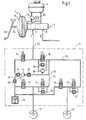
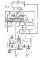
- the one shown in Fig.1 Brake system has two brake circuits I and II, their Structure is completely identical, so the following description one brake circuit also applies to the other.
- the one shown Braking system essentially consists of a brake pressure sensor 1, to the via unspecified hydraulic lines Wheel brake cylinders 17, 18 can be connected, one between the hydraulic pressure generator 1 and the wheel brakes 2, and an electronic controller, not shown with associated sensors.
- the assignment of the wheel brake cylinder 17, 18 the individual brake circuits I, II are hit in such a way that the one wheel brake cylinder 17 either a wheel of a vehicle axle and the other wheel brake cylinder 18 diagonally opposite Wheel of the other vehicle axis is assigned (diagonal division of the brake circuits) or both wheel brake cylinders 17, 18 of the same vehicle axis as shown assigned (black and white division of the brake circuits).
- actuatable pressure transducer 1 consists of a pneumatic Brake booster 5, which is a master brake cylinder, preferably a tandem master cylinder 3 is connected, the Pressure rooms 7, 8 can be connected to a pressure medium reservoir 4 are.
- An actuating rod 34 is on the brake pedal 33 coupled, the actuation of a not shown Control valve enabled by the vehicle driver, the Development of a pneumatic differential pressure in the housing of the Vacuum brake booster 5 controls.
- the hydraulic unit 2 has a motor-pump unit 20, that from a driven by an electric motor, not shown hydraulic return pump 14, whose Suction side via a first check valve 24 and an electromagnetic actuatable switching valve 9 to the first pressure chamber 7 of the master cylinder 3 is connected.
- a second check valve 25 and a damping chamber, not shown to a hydraulic node 21 are connected to both the first wheel brake cylinder 17th leading line section 31 and also to the second wheel brake cylinder 18 leading line section 32.
- a hydraulic Line 23 connects the pressure side of the return pump 14 with the tandem master cylinder 3.
- a third check valve 29 and a pressure relief valve 28 are connected in parallel.
- the mentioned Parallel connection in line section 31 is inserted and exhaust valve 12 for wheel brake pressure relief a connection between the first wheel brake cylinder 17 and a low-pressure accumulator 13 allows a fifth Check valve 30 with the suction side of the return pump 14 connected is.
- an auxiliary pressure source is provided, the effective between the pressure medium reservoir 4 and the master cylinder 3 is arranged.
- the Auxiliary pressure source is in the embodiment shown by a precharge pump driven by an electric motor 22 19 formed, the suction side with the pressure medium reservoir 4 is connected and the pressure side to the Master brake cylinder - pressure chamber 7 (push rod circuit) connected is.
- the precharge pump 19 generates a pressure medium flow, the via the master cylinder outputs, depending on the Switch position of the valves 9,10, either the suction side of the Return pump 14 or fed directly to the wheel brakes 17, 18 becomes.
- the precharge pressure supplied by the precharge pump should be like this be high so that it delimits the second pressure chamber 8 Master brake cylinder piston against the resistance of one against it return spring biasing the direction of actuation can shift to a precharge pressure in the second brake circuit II to create.
- This arrangement has, among other things Advantage that only the pressure medium volume in the second pressure chamber 8 is fed, which is the stroke of the second pressure chamber 8 limiting piston corresponds. This has a better one or more comfortable pedal feel.
- the precharge pump mentioned can be designed in this way that the pressure she applies is just high enough that no displacement of the secondary piston and therefore no The precharge pressure builds up in the second brake circuit.
- the pre-charge pump can be used as a centrifugal, vane, gear or piston pumps and in the pressure medium reservoir 4, in the master cylinder 3 or between the pressure medium reservoir 4 and master brake cylinder 3 may be arranged.
- Drives come in addition to the electric motor 22 already mentioned still both hydraulic and pneumatic drive cylinders in question.
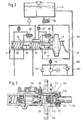
- the master brake cylinder 3 two working chambers 79.80 by a floating piston 83 are separated from each other.
- the push rod piston 82 the directly from the vacuum brake booster 5 or the pedal 33 is driven, is staged, so that a Trailing space 77 is formed.
- the push rod piston 82 borders with a surface with the diameter D to the one working chamber 79, while the surface of the push rod piston 82, the facing away from the working chamber 79, a diameter d having.
- the trailing space 77 thus has an effective area based on the subtraction of the two just mentioned Surfaces.
- the pressure in the trailing space 77 acts on it effective area and drives the push rod piston in the direction to the working chamber 79.
- the trailing space 77 is connected to the reservoir via a line 100 4 connected. There is also a connection between the trailing room and the one working chamber 79 both via a central valve 85, as well as via a check valve 87.
- the central valve 85 is arranged so that it is a movement of the push rod piston 82 in the actuating direction closes.
- the already mentioned also adjoins the trailing space 77 Form pressure pump 19, the suction line 101 directly to the Storage container 4 is connected.
- a check valve or precharge valve 90 between the reservoir 4 and the trailing space 77 provided.
- the pressure at the outlet of the follow-up pump 19 can be limited in different ways, either through a Throttle 102 or a pressure relief valve 103.
- This pressure relief valve 103 can either have a fixed switch point have a fixed pressure at the outlet of the pump or, what is not shown here, from Master cylinder pressure can be controlled in such a way that the pressure at the outlet of the precharge pump cannot increase than the master cylinder pressure.
- Fig. 3 shows the execution of a suitable master cylinder.
- the push rod piston is designed stepped, and has a head 110 in the bore 111 of the master cylinder housing is led.
- One from the master cylinder housing 111 lead out shaft 112 has a smaller diameter on than the head of the push rod piston.
- a ring closure member 113 At the end of the master cylinder housing is a ring closure member 113 with a seal 114 provided, in which the shaft 112 is sealingly guided becomes.
- the annular space 77 is formed, which over a channel 115, which corresponds to line 100, with the connecting piece 116 for the reservoir 4 is connected.
- the precharge valve in the housing of the master brake cylinder 90 inserted.
- the precharge pump 19 closes a cross hole on the channel 115.
- the central valve 85 is formed by a plunger in the Push rod piston, which rests on a valve seat and from a cross member in the basic position of the piston in the open position is held.
- the check valve 87 is a sealing sleeve 120 trained.
- the system works as follows. In all the cases where a Brake pressure must be built up in the brake circuits without the pedal 33 is operated, the precharge pump 19 is turned on and the precharge valve 90 closed. At the same time the isolation valve 10 is blocked in the brake lines, and the electronic switch valve 9 opened so that pressure medium, promoted by the precharge pump 19 in the brake circuit is reached to the suction side of the return pump 14. This promotes the pressure medium to the connected wheel brakes, in who can build up a pressure that can be and exhaust valves adapted to the respective control algorithms is set.
- both Pre-charging the brake circuits as well as an exclusive brake booster respectively.
- a subpoena can in particular also be provided if there is a possibility that Determine the driver's intention to initiate braking, before he presses the brake pedal. Such an intention determined, the precharge pump 19 is turned on and that Pre-charging valve 90 blocked. Now brake fluid penetrates the open central valve 85 and the check valve 87 in the brake circuits. This leads to an overcoming of the intrinsic to the system Empty ways. By pressing the pedal the piston rod becomes 82 shifted, whereby the central valve 85 is closed becomes. As a result, 79 in the push rod brake circuit built up a pressure that is generally greater than that Pressure provided by the pre-charge pump 19 becomes.
- the pressure of the precharge pump is still in the wake room 77 effective, so that this is based on the effective Area, an additional actuating force on the push rod piston exercises, which leads to an increase in pressure in the brake circuits leads.
- an additional actuating force on the push rod piston exercises which leads to an increase in pressure in the brake circuits leads.
- no additional Pressure fluid in the brake circuits can be medium be provided with which the pressure of the precharge pump is limited to the pressure in the brake circuits. This can by means of a pressure relief valve controlled by the master cylinder pressure take place at the outlet of the precharge pump for this ensures that the precharge pressure does not exceed the master cylinder pressure.
- the pre-charge pump can therefore be used in a multifunctional way: On the one hand, it can be used in cases where brake pressure must be built up in the brake circuits without one Pedal actuation takes place, the necessary pressure medium volume for Make available. On the other hand, it can be used for one Pedal actuation a pressure in the wake room available position that increases the pedal force. This can take place unregulated, namely in all cases in which on the basis of special signals it can be determined that the Driver wants to brake quickly. But this can also take place in a controlled manner, e.g. the pressure at the exit of the Pre-charge pump to or less than the master cylinder pressure is set.
- FIGS. 4 to 7 are different control options for operating the hydraulic Brake system with a hydraulic brake assistant function explained.
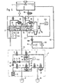
- FIG. 4 shows a combination of those from the previously in Figures 1 and 2 described and thus known elements. Also with reference to the preceding parts of the description for the hydraulic brake assist function, as among others on the description page 12, 2nd paragraph summarized, is now based on examples targeted to the necessary sensors for the control process of the hydraulic brake assistant.
- the movement characteristics of the Brake pedal 33 preferably by means of a displacement sensor 333 and Determination of the pressure in the hydraulic circuit, preferably by means of the working chamber 80 and the pump pressure line 21 arranged pressure sensors 444.
- the resulting resulting sensor signals lead depending on the likewise in a computer, preferably in the ABS control unit, detected driving speed of the vehicle when recognizing a Panic braking by the computer, to the closed position of the Pre-charging valve 90 and to activate the pre-charging pump 19, with which an actuation pressure adding to the pedal force builds up in the master cylinder 3.
- a computer preferably in the ABS control unit, detected driving speed of the vehicle when recognizing a Panic braking by the computer, to the closed position of the Pre-charging valve 90 and to activate the pre-charging pump 19, with which an actuation pressure adding to the pedal force builds up in the master cylinder 3.
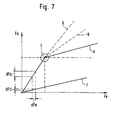
- This is among other things in the Figure 7 illustrates graphically. This increased actuation pressure is achieved that the brake pressure level in the wheel brake cylinders 17,
- FIG. 5 An expedient embodiment of the mode of operation explained for FIG. 4 can be seen from the illustration in FIG. 5.
- This provides for the purpose of being as responsive as possible Response behavior of the hydraulic to Fig. 4 described Brake assist function, a high pressure accumulator 555 on the Pressure side of the precharge pump 19 between the check valve 666 and one connected to the charging line 777 Isolation valve 888 to connect.
- the isolation valve is 888 preferably as an electromagnetically actuated, in the basic position closed 2/2-way valve designed that accordingly the previous explanations for Fig. 4, in the case activation is additionally opened electromagnetically, to the volume in the preloaded high-pressure accumulator 555 in the am Follow-up space 77 connected charging line 888 flow in to let.
- the other end portion of the charge line 888 is through the electromagnetically blocked precharge valve 90 from the pressure medium reservoir 4 separated.
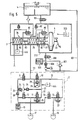
- FIG. 6 shows on the basis of what has already been described in detail Brake system construction an embodiment variant, which differs from the Braking systems according to FIGS. 4 and 5 differs in that instead of a displacement sensor a force sensor 999 on the brake pedal 33 exerted foot power and with the no longer correlating Pressure increase in the brake circuit with a further increase in force every foot force in a computer, preferably in the ABS control unit, is compared to the control point of the pneumatic To determine brake booster 5.
- the precharge pump 19 is carefully activated, to achieve a comfortable pedal feel.
- the pressure reduction in the trailing space 77 as in all of the previously described Embodiments about the deactivation of the Complete preload valve 90. It can also be used if necessary take over the function of the pressure limiter valve 103.
- This embodiment is primarily used for particular small pneumatic brake booster 5 to either an additional hydraulic for pneumatic reinforcement Reinforcement by means of the precharge pump 19 and / or a high pressure accumulator 555 or to cause a vacuum deficit caused pneumatic gain deficit by means of hydraulic boosting effect of the precharge pump 19 and / or to compensate for a high pressure accumulator 555.
- FIG. 7 shows with reference to the representation according to FIG. 6 a force diagram in which the characteristic a of the pneumatic Brake booster 5 and one around the hydraulic booster characteristic b Extended representation of the characteristic curve a drawn is.
- the increase in force plotted over the ordinate dFa of the control force Fa as well as that plotted on the abscissa Force increase dFe of the input force Fe caused by the foot force is generated can be described using the above Determine pressure sensors 444 and with the values of the force sensor 999 on the pedal, so that one relatively small force increase ratio dFa / dFe the desired Control point I of the pneumatic brake booster 5 is achieved at which the hydraulic additional gain (Characteristic curve b) is set by the precharge pump 19. The same applies if the vacuum fails.
Landscapes
- Engineering & Computer Science (AREA)
- Transportation (AREA)
- Mechanical Engineering (AREA)
- Physics & Mathematics (AREA)
- Fluid Mechanics (AREA)
- Regulating Braking Force (AREA)
Abstract
Description
Die Erfindung bezieht sich auf eine hydraulische Bremsanlage und ein Verfahren zu deren Betrieb gemäß dem Oberbegriff des Anspruchs 1 bzw. 8.The invention relates to a hydraulic brake system and a method for their operation according to the preamble of Claims 1 and 8 respectively.
Eine derartige Bremsanlage ist aus der DE 41 108 51 A1 bekannt. Die Bremskreise, die an den Hauptbremszylinder angeschlossen sind, enthalten Mittel (Rückförderpumpen, Ventile), die mittels eines elektronischen Reglers angesteuert werden. Je nachdem, welcher Regelalgorithmus in dem elektronischen Regler implementiert ist, kann mit einer solchen Anlage z.B. ein Blockieren der Räder während eines durch den Fahrer eingeleiteten Bremsvorganges verhindert werden. In der erwähnten Offenlegungsschrift wird außerdem vorgeschlagen, die hydraulische Bremsanlage einzusetzen, um ein Durchdrehen der angetriebenen Räder mittels eines entsprechenden Antriebsschlupfreglers zu verhindern.Such a brake system is known from DE 41 108 51 A1. The brake circuits connected to the master cylinder are, contain means (return pumps, valves), which means of an electronic controller can be controlled. Depending on, which control algorithm is implemented in the electronic controller with such a system, e.g. a blocking the wheels during a braking process initiated by the driver be prevented. In the aforementioned publication the hydraulic brake system is also proposed used to spin the driven wheels to prevent by means of an appropriate traction controller.
Um eine solche Regelung durchführen zu können, muß die Anlage mit Mitteln ausgestattet werden, die in der Lage sind, zumindest den Bremskreis, der die angetriebenen Räder enthält, mit Druckmittel zu füllen. Dazu ist eine Vorladepumpe vorgesehen, die aus dem Vorratsbehälter des Hauptbremszylinders in einem Nachlaufraum des Hauptbremszylinders fördert, der über ein Zentralventil mit der Arbeitskammer und damit mit einem Bremskreis der Anlage in Verbindung steht.In order to be able to carry out such a regulation, the system must be equipped with means that are capable, at least the brake circuit containing the driven wheels with To fill pressure medium. A precharge pump is provided for this purpose, from the reservoir of the master cylinder in one Follows the master cylinder that promotes a Central valve with the working chamber and thus with a brake circuit the system is connected.
Zur Durchführung einer Antriebsschlupfregelung wird zunächst mittels der Vorladepumpe in den angeschlossenen Bremskreisen ein Bremsdruck aufgebaut, wodurch das Rad, das zum Durchdrehen neigt, abgebremst wird. To carry out traction control, first of all by means of the pre-charge pump in the connected brake circuits a brake pressure builds up, causing the wheel to spin tends to slow down.
Ähnliche Bremsanlagen werden auch eingesetzt, um an allen vier Rädern eines Fahrzeuges Bremskräfte aufzubauen, die jeweils radindividuell eingestellt werden, so daß gezielt Momente um die Hochachse des Fahrzeuges aufgebaut werden können, die das Fahrzeug in kritischen Fahrsituationen stabil halten sollen.Similar braking systems are also used to work on all four Wheels of a vehicle to build up braking forces, each can be set individually for the wheel, so that targeted moments around the vertical axis of the vehicle can be built, which the Keep the vehicle stable in critical driving situations.
In der GB 21 47 963 A1 ist ebenfalls eine Bremsanlage mit einer Vorladepumpe beschrieben, mit der sowohl eine Antiblokkierregelung als auch eine Antriebsschlupfregelung durchgeführt werden kann. Die hydraulische Schaltung ist aber so aufgebaut, daß die Pumpe nicht unmittelbar in die Bremskreise fördert, sondern Druckmittel an der Saugseite der Rückförderpumpe zur Verfügung stellt, die diese weiter in die Bremskreise leitet, damit dort ein Bremsdruck aufgebaut werden kann.In GB 21 47 963 A1 there is also a braking system with a Pre-charge pump described with both an anti-lock control as well as a traction control can be. The hydraulic circuit is designed so that the pump is not directly in the brake circuits promotes, but pressure medium on the suction side of the return pump provides this further into the brake circuits conducts so that a brake pressure can be built up there.
In beiden beschriebenen Fällen ist dem Hauptzylinder ein Bremskraftverstärker vorgeschaltet, der die auf den Hauptbremszylinder ausgeübte Pedalkraft verstärkt. Derartige Verstärker sind notwendig, da nicht in allen Fällen davon ausgegangen werden kann, daß der Fahrer oder die Fahrerin allein die notwendigen Betätigungskräfte für eine Bremsung aufbringen kann. Zum Einsatz kommen im allgemeinen entweder sogenannte pneumatische oder hydraulische Verstärker. Die pneumatischen Verstärker nutzen zu ihrem Antrieb den Druckunterschied zwischen der Atmosphäre und dem Druck im Ansaugbereich eines Verbrennungsmotors. Da der Druckunterschied sehr klein ist, muß die wirksame Fläche des Verstärkers sehr groß gewählt werden, was zur Folge hat, daß diese einen relativ großen Raum im Motorraum einnehmen.In both cases described, the master cylinder is on Brake booster upstream, which on the master brake cylinder applied pedal force is increased. Such amplifiers are necessary as not assumed in all cases can be that the driver alone apply the necessary actuation forces for braking can. Either so-called are generally used pneumatic or hydraulic booster. The pneumatic Amplifiers use the pressure difference between to drive them the atmosphere and the pressure in the intake area of an internal combustion engine. Since the pressure difference is very small, must the effective area of the amplifier must be chosen very large, which has the consequence that this has a relatively large space in the engine compartment take in.
Dieses Problem tritt bei hydraulischen Verstärkern nicht auf, da diese mit einem hydraulischen Hochdruckspeicher versehen sind. Diese Verstärker sind allerdings recht aufwendig zu bauen, da besondere Sicherheitserfordernisse erfüllt werden müssen. Außerdem muß das Regelventil des Verstärkers sehr feinfühlig arbeiten, so daß es im allgemeinem sehr aufwendig konstruiert ist. This problem does not occur with hydraulic amplifiers, because they are equipped with a hydraulic high-pressure accumulator are. However, these amplifiers are quite complex to build, because special security requirements have to be met. In addition, the control valve of the amplifier must be very sensitive work, so that it is generally very complex is.
Die Erfindung beruht daher auf der Aufgabe, für einen pedalbetätigten Bremsdruckgeber in einer hydraulischen Bremsanlage gemäß dem Oberbegriff des Anspruchs 1 eine effektive Pedalkraftverstärkung vorzusehen. Dazu schlägt die Erfindung vor, daß die Pumpe eine Vorladepumpe ist, und daß die Vorladepumpe zur Verstärkung der Pedalkraft spätestens mit Beginn einer Pedalbetätigung eingeschaltet wird, wobei der auf die Wirkfläche einwirkende Vorladepumpendruck eine Pedalkraftverstärkung erzeugt. Durch die Erfindung ist es damit möglich, den Hauptbremszylinder als hydraulischen Bremsassistenten wirksam werden zu lassen.The invention is therefore based on the task for a pedal-operated Brake pressure sensor in a hydraulic brake system according to the preamble of claim 1 an effective pedal force boost to provide. To this end, the invention proposes that the pump is a precharge pump, and that the precharge pump to amplify the pedal force at the latest is switched on at the start of a pedal actuation, the precharge pump pressure acting on the active surface producing a pedal force boost. Through the Invention, it is possible to use the master cylinder as hydraulic brake assist to take effect.
Diese hydraulische Bremsassistentenfunktion wird durch einen Rechner, vorzugsweise einem ABS-Steuergerät, gesteuert. Der Rechner verarbeitet hierzu als Eingangssignale die Bewegungscharakteristik des Bremspedals, welche vorzugsweise mit einem Weg- oder Kraftsensor ermittelt wird, den Hydraulikdruck im Bremssystem, welcher mit Drucksensoren erfaßt wird, und vergleicht die Weg- und Druckcharakteristik mit den Signalen welche die Fahrzeuggeschwindigkeit darstellen. Erkennt der Rechner aus diesem Informationsvergleich eine Panikbremsung, aktiviert er Vorladepumpe und Vorladeventil und setzt damit die Bremsassistentenfunktion des Hauptbremszylinders in Gang.This hydraulic brake assist function is performed by a computer, preferably an ABS control unit, controlled. The computer processes the motion characteristics as input signals of the brake pedal, which preferably with a path or Force sensor is determined, the hydraulic pressure in the brake system, which is recorded with pressure sensors and compares the and pressure characteristics with the signals representing the vehicle speed represent. The computer recognizes from this Panic braking information comparison, he activates the precharge pump and pre-charging valve and thus sets the brake assist function of the master brake cylinder in motion.
Die Vorladepumpe erfüllt zwei Zwecke. Aus der DE 4037468A ist ein System bekannt, mit dem versucht wird, aufgrund des Verhaltens des Fahrers (rasches Lösen des Gaspedals, schnelle Bewegung des rechten Fußes auf das Bremspedal zu) schon vor der eigentlichen Pedalbetätigung auf eine beabsichtigte Bremsbetätigung zu schließen. Wenn dies möglich ist, kann in dieser Vorbremsphase die Vorladepumpe eingeschaltet werden, so daß die Bremskreise schon so weit gefüllt werden können, daß Leerwege ausgeglichen sind, bevor der Fahrer das Pedal niederdrückt. Dies hat den Vorteil, daß mit Betätigen des Pedals sofort ein Bremsdruck aufgebaut werden kann, ohne daß zunächst Leerwege durchfahren werden müssen. The pre-charge pump serves two purposes. From DE 4037468A known a system that is attempted based on behavior of the driver (quick release of the accelerator pedal, quick movement right foot towards the brake pedal) before the Actual pedal actuation on an intended brake actuation close. If this is possible, this can Pre-braking phase, the precharge pump can be switched on, so that the Brake circuits can be filled so far that empty runs are balanced before the driver depresses the pedal. This has the advantage that when you press the pedal immediately one Brake pressure can be built up without first having to travel empty have to be driven through.
In einem zweiten Schritt erfüllt die Vorladepumpe eine echte Verstärkerfunktion. Sie erzeugt im Nachlaufraum einen Bremsdruck, der auf eine wirksame Fläche des Druckstangenkolbens des Hauptzylinders geleitet wird. Die wirksame Fläche entsteht, weil der Durchmesser des Druckstangenkolbens größer ist als des Schaftes des Druckstangenkolbens, der durch die Endabdichtung des Hauptzylinders geführt ist. Damit wird zusätzlich eine Kraft auf den Druckstangenkolben ausgeübt, der sich aus der Größe der wirksamen Fläche und dem von der Vorladepumpe aufgebauten Druck ergibt. Dies wiederum hat zur Folge, daß der üblicherweise vorgeschaltete pneumatische Verstärker eine nicht so große wirksame Fläche aufzuweisen braucht, und damit kleiner baut. Unter Umständen kann sogar ganz auf einen zusätzlichen Verstärker verzichtet werden. Um zu vermeiden, daß in der Verstärkerphase Druckmittel, das von der Pumpe gefördert wird, in den Bremskreis gelangt, kann ein Druckbegrenzungsventil vorgesehen werden, dessen Öffnungsdruck vom Hauptzylinderdruck bestimmt wird. Der Druck im Nachlaufraum ist damit stets kleiner als der Druck in der Arbeitskammer des Hauptzylinders, so daß über die Rückschlagmanschetten am Druckstangenkolben kein Druckmittel von der Nachlaufkammer in die Arbeitskammer fließen kann. Der Druchaufbau in der Nachlaufkammer kann proportional zur aufgebrachten Fußkraft erfolgen. In diesem Fall liegt eine Verstärkerfunktion vor. Der Aufbau kann aber auch überproportional bis zur Vollausteuerung erfolgen. In diesem Fall liegt eine Bremsassistenzfunktion vor, mit der es möglich ist das Fahrzeug in bestimmten Situationen über das Maß hinaus zu verzögern, das vom Fahrer durch die Pedalbetätigung vorgegeben ist.In a second step, the pre-charge pump fulfills a real one Amplifier function. It creates a brake pressure in the trailing area, on an effective area of the push rod piston of the master cylinder. The effective area arises because the diameter of the push rod piston is larger than the stem of the pushrod piston that passes through the end seal of the master cylinder is guided. This will add exerted a force on the push rod piston from the size of the effective area and that of the precharge pump pressure builds up. This in turn has the consequence that the usually upstream pneumatic amplifier one does not need to have such a large effective area, and thus builds smaller. It may even be possible to add an additional one Amplifiers are dispensed with. To avoid that in the booster phase pressure medium, which is pumped is in the brake circuit, a pressure relief valve can be provided, the opening pressure of the master cylinder pressure is determined. The pressure in the wake room is thus always less than the pressure in the working chamber of the Master cylinder, so that on the check sleeves on Push rod piston no pressure medium from the trailing chamber in the working chamber can flow. The build-up in the trailing chamber can be proportional to the foot force applied. In this case there is an amplifier function. The Construction can also be disproportionate up to full control respectively. In this case there is a brake assist function with which it is possible the vehicle in certain situations to delay beyond the extent required by the driver pedal actuation is predefined.
Die Besonderheit der vorgeschlagenen Bremsanlage besteht somit darin, daß die Vorladepumpe sowohl eingesetzt wird, um Druckmittel in den Fällen zur Verfügung zu stellen, in denen keine Pedalbetätigung erfolgt, als auch Druckmittel zur Verfügung zu stellen, um eine Verstärkerfunktion bzw. Bremsassistenzfunktion zu realisieren.The peculiarity of the proposed brake system thus exists in that the precharge pump is used both to pressure medium to be made available in cases where none Pedal actuation is available as well as pressure medium to an amplifier function or braking assistance function to realize.
Die Vorladepumpe kann, wie z. B. in der GB 21 47 963 A1 in den
einzigen Verbindungspfad zwischen dem Vorratsbehälter und Arbeitskammer
geschaltet werden. Dies setzt aber voraus, daß die
Pumpe im ausgeschalteten Zustand in beiden Richtungen durchströmt
werden kann. Die Pumpe kann aber auch erfindungsgemäß parallel zu einem
Sperrventil (Vorladeventil) geschaltet werden, daß in einem
Parallelzweig den Nachlaufraum mit dem Vorratsbehälter verbindet.
Dieses Sperrventil wird geschlossen, sobald die Pumpe
eingeschaltet wird. Dieses Ventil kann auch getaktet angesteuert
dazu eingesetzt werden, den Druck der Vorladepumpe zu regulieren. The pre-charge pump can, such as. B. in
Im folgenden wird die Erfindung anhand mehrerer Ausführungsbeispiele näher erläutert. Dazu zeigt die
- Fig. 1
- den hydraulischen Schaltplan einer nicht beanspruchten hydraulischen Bremsanlage.
- Fig. 2
- zeigt ebenfalls in schematischer Darstellung den erfindungsgemäßen Anschluß einer Vorladepumpe an einen Hauptbremszylinder.
- Fig. 3
- zeigt die Ausführung eines geeigneten Hauptbremszylinders.
- Fig. 4-7
- Merkmale zur Ansteuerung einer erfindungsgemäßen hydraulischen Bremsanlage mit hydraulischen Bremsassistenten.
- Fig. 1
- the hydraulic circuit diagram of an unused hydraulic brake system.
- Fig. 2
- also shows a schematic representation of the connection of a precharge pump to a master brake cylinder according to the invention.
- Fig. 3
- shows the execution of a suitable master cylinder.
- Fig. 4-7
- Features for controlling a hydraulic brake system according to the invention with hydraulic brake assistants.
Die in Fig.1 dargestellte
Bremsanlage weist zwei Bremskreise I und II auf, deren
Aufbau völlig identisch ist, so daß die folgende Beschreibung
eines Bremskreises ebenso auf den anderen zutrifft. Die gezeigte
Bremsanlage besteht im wesentlichen aus einem Bremsdruckgeber
1, an den über nicht näher bezeichnete hydraulische Leitungen
Radbremszylinder 17,18 anschließbar sind, einem zwischen
dem Bremsdruckgeber 1 und den Radbremsen geschalteten Hydroaggregat
2, sowie einem nicht gezeigten elektronischen Regler
mit zugehöriger Sensorik. Die Zuordnung der Radbremszylinder
17,18 den einzelnen Bremskreisen I, II ist derart getroffen,
daß der eine Radbremszylinder 17 entweder einem Rad einer Fahrzeugachse
und der andere Radbremszylinder 18 dem diagonal gegenüberliegenden
Rad der anderen Fahrzeugachse zugeordnet ist
(diagonale Aufteilung der Bremskreise) oder aber beide Radbremszylinder
17, 18 derselben Fahrzeug-achse, wie gezeigt,
zugeordnet sind (Schwarzweiß-Aufteilung der Bremskreise). The one shown in Fig.1
Brake system has two brake circuits I and II, their
Structure is completely identical, so the following description
one brake circuit also applies to the other. The one shown
Braking system essentially consists of a brake pressure sensor
1, to the via unspecified hydraulic lines
Der vom Fahrer des Kraftfahrzeugs mittels eines Bremspedals 33
betätigbare Druckgeber 1 besteht aus einem pneumatischen
Bremskraftverstärker 5, dem ein Hauptbremszylinder, vorzugsweise
ein Tandemhauptzylinder 3 nachgeschaltet ist, dessen
Druckräume 7,8 mit einem Druckmittelvorratsbehälter 4 verbindbar
sind. An das Bremspedal 33 ist eine Betätigungsstange 34
angekoppelt, die eine Betätigung eines nicht dargestellten
Steuerventils durch den Fahrzeugfahrer ermöglicht, das den
Aufbau eines pneumatischen Differenzdruckes im Gehäuse des
Unterdruckbremskraftverstärkers 5 steuert.That of the driver of the motor vehicle by means of a
Das Hydroaggregat 2 weist ein Motor-Pumpen-Aggregat 20 auf,
das aus einer durch einen nicht gezeigten Elektromotor angetriebenen
hydraulischen Rückförderpumpe 14 besteht, deren
Saugseite über ein erstes Rückschlagventil 24 sowie ein elektromagnetisch
betätigbares Schaltventil 9 an den ersten Druckraum
7 des Hauptbremszylinders 3 angeschlossen ist. Von der
Druckseite der Rückförderpumpe 14 strömt das Druckmittel über
ein zweites Rückschlagventil 25 und eine nicht gezeigte Dämpfungskammer
zu einem hydraulischen Knotenpunkt 21. An diesen
angeschlossen ist sowohl ein zum ersten Radbremszylinder 17
führender Leitungsabschnitt 31 als auch ein zum zweiten Radbremszylinder
18 führenden Leitungsabschnitt 32. Eine hydraulische
Leitung 23 verbindet die Druckseite der Rückförderpumpe
14 mit dem Tandemhauptzylinder 3. Außerdem ist zwischen dem
Knotenpunkt 21 und dem Hauptbremszylinder 3 ein vorzugsweise
elektromagnetisch betätigbares Trennventil 10 geschaltet, dem
sowohl ein drittes Rückschlagventil 29 als auch ein Druckbegrenzungsventil
28 parallelgeschaltet sind. Zur Modulation des
im ersten Radbremszylinder 17 eingesteuerten Drucks dienen
eine Parallelschaltung eines Einlaß- (11) mit einem vierten
Rückschlagventil 26 sowie ein Auslaßventil 12, wobei die erwähnte
Parallelschaltung im Leitungsabschnitt 31 eingefügt ist
und das Auslaßventil 12 zum Zwecke eines Radbremsdruckabbaus
eine Verbindung zwischen dem ersten Radbremszylinder 17 und
einem Niederdruckspeicher 13 ermöglicht, der über ein fünftes
Rückschlagventil 30 mit der Saugseite der Rückförderpumpe 14
verbunden ist.The
Um in dem zum betrachteten Bremskreis gehörenden zweiten Radbremszylinder
18 analog zum bereits betrachteten Radbremszylinder
17 den darin eingesteuerten hydraulischen Druck regulieren
zu können, sind eine zweite Parallelschaltung eines
zweiten Einlaß- (15) mit einem sechsten Rückschlagventil 27
sowie ein zweites Auslaßventil 16 vorgesehen, wobei die erwähnte
Parallelschaltung im Leitungsabschnitt 32 eingefügt ist
und das Auslaßventil 16 zum Zwecke eines Radbremsdruckabbaus
eine Verbindung zwischen dem zweiten Radbremszylinder 18 und
dem Niederdruckspeicher 13 herstellt.To in the second wheel brake cylinder belonging to the brake circuit under
Um im Bedarfsfall, beispielsweise bei sehr niedrigen Temperaturen,
der Rückförderpumpe 14 das Druckmittel unter einem höheren
Druck zur Verfügung zu stellen, bzw. ein Vorfüllen der
Radbremsen 17,18 zu erreichen, ist eine Hilfsdruckquelle vorgesehen,
die wirkungsmäßig zwischen dem Druckmittelvorratsbehälter
4 und dem Hauptbremszylinder 3 angeordnet ist. Die
Hilfsdruckquelle ist bei dem gezeigten Ausführungsbeispiel
durch eine durch einen Elektromotor 22 angetriebene Vorladepumpe
19 gebildet, deren Saugseite mit dem Druckmittelvorratsbehälter
4 in Verbindung steht und deren Druckseite an die
Hauptbremszylinder - Druckraum 7 (Druckstangenkreis) angeschlossen
ist. Die Vorladepumpe 19 erzeugt einen Druckmittelstrom,
der über die Hauptbremszylinderausgänge, je nach der
Schaltstellung der Ventile 9,10, entweder der Saugseite der
Rückförderpumpe 14 oder direkt den Radbremsen 17,18 zugeführt
wird. Der von der Vorladepumpe gelieferte Vorladedruck soll so
hoch sein, daß er den den zweiten Druckraum 8 begrenzenden
Hauptbremszylinderkolben gegen den Widerstand einer ihn entgegen
der Betätigungsrichtung vorspannenden Rückstellfeder
verschieben kann, um auch im zweiten Bremskreis II einen Vorladedruck
zu erzeugen. Diese Anordnung hat unter anderem den
Vorteil, daß in den zweiten Druckraum 8 nur das Druckmittelvolumen
eingespeist wird, welches dem Hub des den zweiten Druckraum
8 begrenzenden Kolbens entspricht. Dies hat ein besseres
bzw. angenehmeres Pedalgefühl zur Folge.If necessary, for example at very low temperatures,
the
Wenn im Fahrzeug nur eine Achse mit hoher Systemdynamik erforderlich ist, kann die erwähnte Vorladepumpe so ausgelegt werden, daß der von ihr aufgebrachte Druck gerade so hoch ist, daß keine Verschiebung des Sekundärkolbens und demnach kein Vorladedruckaufbau im zweiten Bremskreis stattfindet.If only one axle with high system dynamics is required in the vehicle the precharge pump mentioned can be designed in this way that the pressure she applies is just high enough that no displacement of the secondary piston and therefore no The precharge pressure builds up in the second brake circuit.
Die Vorladepumpe kann als Kreisel-, Flügelzellen-, Zahnrad-
oder Kolbenpumpen ausgeführt und im Druckmittelsvorratsbehälter
4, im Hauptbremszylinder 3 oder zwischen Druckmittelvorratsbehälter
4 und Hauptbremszylinder 3 angeordnet sein. Als
Antriebe kommen außer dem bereits erwähnten Elektromotor 22
noch sowohl hydraulische als auch pneumatische Antriebszylinder
in Frage.The pre-charge pump can be used as a centrifugal, vane, gear
or piston pumps and in the
Wie der Fig. 2 zu entnehmen ist, weist der Hauptbremszylinder
3 zwei Arbeitskammern 79,80 auf, die durch einen Schwimmkolben
83 voneinander getrennt sind. Der Druckstangenkolben 82, der
unmittelbar vom Unterdruckbremskraftverstärker 5 bzw. dem Pedal
33 angetrieben wird, ist gestuft ausgeführt, so daß ein
Nachlaufraum 77 gebildet ist. Der Druckstangenkolben 82 grenzt
mit einer Fläche mit dem Durchmesser D an die eine Arbeitskammer
79, während die Fläche des Druckstangenkolben 82, die
von der Arbeitskammer 79 abgewandt ist, einen Durchmesser d
aufweist. Der Nachlaufraum 77 weist damit eine wirksame Fläche
auf, die sich aus der Subtraktion der beiden eben genannten
Flächen ergibt. Der Druck im Nachlaufraum 77 wirkt auf diese
wirksame Fläche und treibt den Druckstangenkolben in Richtung
auf die Arbeitskammer 79. As can be seen from FIG. 2, the
Der Nachlaufraum 77 ist über eine Leitung 100 mit dem Vorratsbehälter
4 verbunden. Außerdem besteht eine Verbindung zwischen
dem Nachlaufraum und der einen Arbeitskammer 79 sowohl
über ein Zentralventil 85, als auch über ein Rückschlagventil
87. Das Zentralventil 85 ist so angeordnet, daß es sich bei
einer Bewegung des Druckstangenkolbens 82 in Betätigungsrichtung
schließt.The trailing
An den Nachlaufraum 77 schließt außerdem die schon erwähnte
Vordruckpumpe 19 an, deren Saugleitung 101 unmittelbar mit dem
Vorratsbehälter 4 verbunden ist. Um zu verhindern, daß Druckmittel,
das von der Pumpe 19 gefördert wird, wieder in den
Vorratsbehälter 4 gelangt, ist ein Sperrventil oder Vorlade-ventil
90 zwischen dem Vorratsbehälter 4 und dem Nachlaufraum
77 vorgesehen. Der Druck am Ausgang der Nachlaufpumpe 19 kann
auf verschiedene Weise begrenzt werden, entweder über eine
Drossel 102 oder ein Druckbegrenzungsventil 103. Dieses Druckbegrenzungsventil
103 kann entweder einen festen Umschaltpunkt
aufweisen, also einen festen Druck am Ausgang der Pumpe einstellen
oder aber, was hier nicht näher dargestellt ist, vom
Hauptzylinderdruck angesteuert werden, und zwar derart, daß
der Druck am Ausgang der Vorladepumpe nicht größer werden kann
als der Hauptzylinderdruck.The already mentioned also adjoins the trailing
Die Fig. 3 zeigt die Ausführung eines geeigneten Hauptzylinders.
Der Druckstangenkolben ist gestuft ausgeführt, und weist
einen Kopf 110 auf, der in der Bohrung 111 des Hauptzylindergehäuses
geführt ist. Ein aus dem Hauptzylindergehäuse 111
herausgeführter Schaft 112 weist einen kleineren Durchmesser
auf als der Kopf des Druckstangenkolbens. Am Ende des Hauptzylindergehäuses
ist ein Ringverschlußteil 113 mit einer Dichtung
114 vorgesehen, in der der Schaft 112 dichtend geführt
wird. Zwischen dem rückwärtigen Ende des Kopfes 110 und dem
Verschlußteil 113 ist der Ringraum 77 ausgebildet, der über
einen Kanal 115, der der Leitung 100 entspricht, mit dem Anschlußstutzen
116 für den Vorratsbehälter 4 verbunden ist. In
diese Leitung ist im Gehäuse des Hauptbremszylinders das Vorladeventil
90 eingefügt. Die Vorladepumpe 19 schließt über
eine Querbohrung an den Kanal 115 an.Fig. 3 shows the execution of a suitable master cylinder.
The push rod piston is designed stepped, and has
a
Das Zentralventil 85 wird gebildet durch einen Stößel im
Druckstangenkolben, der an einem Ventilsitz anliegt und von
einem Querglied in der Grundstellung des Kolbens in Offenstellung
gehalten wird. Das Rückschlagventil 87 ist als Dichtmanschette
120 ausgebildet.The
Die Anlage arbeitet wie folgt. In all den Fällen, in denen ein
Bremsdruck in den Bremskreisen aufgebaut werden muß, ohne daß
das Pedal 33 betätigt wird, wird die Vorladepumpe 19 eingeschaltet
und das Vorladeventil 90 geschlossen. Gleichzeitig
wird das Trennventil 10 in den Bremsleitungen gesperrt, sowie
das elektronische Umschaltventil 9 geöffnet, so daß Druckmittel,
das von der Vorladepumpe 19 in den Bremskreis gefördert
wird, zur Saugseite der Rückförderpumpe 14 gelangt. Diese fördert
das Druckmittel zu den angeschlossenen Radbremsen, in
denen ein Druck aufgebaut werden kann, der mittels der Ein-
und Auslaßventile den jeweiligen Regelalgorithmen angepaßt
eingestellt wird.The system works as follows. In all the cases where a
Brake pressure must be built up in the brake circuits without
the
Bei einer Bremsbetätigung durch den Fahrer kann sowohl eine
Vorladung der Bremskreise als auch eine ausschließliche Bremskraftverstärkung
erfolgen. Eine Vorladung kann insbesondere
auch dann vorgesehen sein, wenn die Möglichkeit besteht, die
Absicht des Fahrers, eine Bremsung einzuleiten, zu ermitteln,
bevor dieser das Bremspedal betätigt. Wird eine solche Absicht
festgestellt, wird die Vorladepumpe 19 eingeschaltet und das
Vorladeventil 90 gesperrt. Nun dringt Bremsflüssigkeit über
das offene Zentralventil 85 sowie das Rückschlagventil 87 in
die Bremskreise. Dies führt zu einer Überwindung der systemimmanenten
Leerwege. Durch die Pedalbetätigung wird der Druckstangenkolben
82 verschoben, wodurch das Zentralventil 85 geschlossen
wird. Dadurch wird in dem Druckstangenbremskreis 79
ein Druck aufgebaut, der im allgemeinen größer ist als der
Druck, der von der Vorladepumpe 19 zur Verfügung gestellt
wird. Der Druck der Vorladepumpe ist aber weiterhin im Nachlaufraum
77 wirksam, so daß dieser bezogen auf die wirksame
Fläche, eine zusätzliche Betätigungskraft auf den Druckstangenkolben
ausübt, der zu einer Druckerhöhung in den Bremskreisen
führt. Um sicherzustellen, daß in dieser Phase kein zusätzliches
Druckmittel in die Bremskreise gelangt, können Mittel
vorgesehen werden, mit denen der Druck der Vorladepumpe
auf den Druck in den Bremskreisen beschränkt wird. Dies kann
mittels eines vom Hauptzylinderdruck gesteuerten Druckbegrenzungsventils
erfolgen, das am Ausgang der Vorladepumpe dafür
sorgt, daß der Vorladedruck nicht größer wird als der Hauptbremszylinderdruck.When the driver applies the brakes, both
Pre-charging the brake circuits as well as an exclusive brake booster
respectively. A subpoena can in particular
also be provided if there is a possibility that
Determine the driver's intention to initiate braking,
before he presses the brake pedal. Such an intention
determined, the
Die Vorladepumpe kann somit multifunktionell eingesetzt werden: Einerseits kann sie in den Fällen, in denen ein Bremsdruck in den Bremskreisen aufgebaut werden muß, ohne daß eine Pedalbetätigung erfolgt, das notwendige Druckmittelvolumen zur Verfügung stellen. Auf der anderen Seite kann sie bei einer Pedalbetätigung einen Druck im Nachlaufraum zur Verfügung stellen, der eine Verstärkung der Pedalkraft bewirkt. Dies kann ungeregelt erfolgen, nämlich in all den Fällen, in denen aufgrund besonderer Signale festgestellt werden kann, daß der Fahrer eine rasche Bremsung durchführen möchte. Dies kann aber auch geregelt erfolgen, indem z.B. der Druck am Ausgang der Vorladepumpe auf den Hauptzylinderdruck oder nur wenig darunter eingestellt wird.The pre-charge pump can therefore be used in a multifunctional way: On the one hand, it can be used in cases where brake pressure must be built up in the brake circuits without one Pedal actuation takes place, the necessary pressure medium volume for Make available. On the other hand, it can be used for one Pedal actuation a pressure in the wake room available position that increases the pedal force. This can take place unregulated, namely in all cases in which on the basis of special signals it can be determined that the Driver wants to brake quickly. But this can also take place in a controlled manner, e.g. the pressure at the exit of the Pre-charge pump to or less than the master cylinder pressure is set.
Wichtige Aspekte der Erfindung sind darin zu sehen, daß bei
Bedarf einer zusätzlichen Bremskraftunterstützung des pneumatischen
Bremskraftverstärkers 5 die Vorladepumpe 19 angestellt
und das Vorlade-Ventil im Nachlaufbereich geschlossen wird. Important aspects of the invention can be seen in the fact that
Requires an additional braking force support for the
Durch Druckaufbau im Nachlaubereich und unter Berücksichtigung
des Flächenverhältnis wird eine hydraulische Unterstützungskraft
auf dem Druckstangenkolben 110 wirksam. Dadurch läßt
sich ein hydraulischer Bremsassistent verwirklichen. Die
Druckregelung kann hierbei über getaktete Pumpenansteuerung
oder Taktung des Vorladeventils 90 erfolgen. Zusätzlich kann,
bei Systemen mit Antriebsschlupfregelung und Fahrdynamikregelung
eine weitere Druckerhöhung in Kombination mit der Vorladepumpe
19 durch das Öffnen des Schaltventils 9 und Druckaufbau
über die Rückförderpumpe 14 in den Radbremsen 17,18 ermöglicht
werden.By building up pressure in the after-run area and taking into account
the area ratio becomes a hydraulic support force
effective on the
Generell kann bei Vorhandensein einer Vorladepumpe 19 der
Bremskraftverstärker 5 kleiner ausgeführt werden und die Vorladepumpe
19 bei Bedarf zur Servounterstützung angesteuert
werden. Daneben ist die Kombination Panik-Bremshilfe in Kombination
mit einem standardmäßigen Bremsdruckverstärker 5 möglich.In general, in the presence of a
Anhand den nachfolgenden Abbildungen gemäß den Fig. 4 bis 7 werden verschiedene Ansteuermöglichkeiten zum Betrieb der hydraulischen Bremsanlage mit einer hydraulischen Bremsassistentenfunktion erläutert.Using the following illustrations according to FIGS. 4 to 7 are different control options for operating the hydraulic Brake system with a hydraulic brake assistant function explained.
Die Figur 4 zeigt hierzu eine Kombination der aus den zuvor in
den Figuren 1 und 2 beschriebenen und damit bekannten Elementen.
Gleichfalls unter Bezugnahme auf die vorangegangenen Beschreibungsteile
zur hydraulischen Bremsassistentenfunktion,
wie unter anderem auf der Beschreibungsseite 12, 2. Absatz
zusammenfassend ausgeführt wurde, wird nunmehr anhand von Beispielen
gezielt auf die notwendige Sensorik für das Ansteuerverfahren
des hydraulischen Bremsassistenten eingegangen.For this purpose, FIG. 4 shows a combination of those from the previously in
Figures 1 and 2 described and thus known elements.
Also with reference to the preceding parts of the description
for the hydraulic brake assist function,
as among others on the
Hierzu bedarf es der Erfassung der Bewegungscharakteristik des
Bremspedals 33, vorzugsweise mittels eines Wegsensors 333 und
Feststellung des jeweils im Hydraulikkreis anstehenden Drucks,
vorzugsweise mittels an der Arbeitskammer 80 und der Pumpendruckleitung
21 angeordneten Drucksensoren 444. Die daraus
resultierenden Sensorsignale führen in Abhängigkeit von der
gleichfalls in einem Rechner, vorzugsweise im ABS-Steuergerät,
erfaßten Fahrgeschwindigkeit des Fahrzeugs, beim Erkennen einer
Panikbremsung durch den Rechner, zur Schließstellung des
Vorladeventils 90 sowie zu einer Aktivierung der Vorladepumpe
19, womit sich ein zur Pedalkraft addierender Betätigungsdruck
im Hauptbremszylinder 3 aufbaut. Dies ist unter anderem in der
Figur 7 graphisch verdeutlicht. Durch diesen erhöhten Betätigungsdruck
wird erreicht, daß das Bremsdruckniveau in den Radbremszylindern
17,18 möglichst nahe an den Blockierdruck herangeführt
werden kann. Dies führt zu einem möglichst kurzen
Bremsweg, ohne eine Notwendigkeit zur zusätzlichen Pedalkraftsteigerung.To do this, the movement characteristics of the
Eine zweckmäßige Ausgestaltung der zu Fig. 4 erläuterten Funktionsweise
geht aus der Darstellung gemäß Figur 5 hervor. Diese
sieht vor, zum Zwecke eines möglichst reaktionsschnellen
Ansprechverhaltens der zu Fig. 4 beschriebenen hydraulischen
Bremsassistentenfunktion, einen Hochdruckspeicher 555 an der
Druckseite der Vorladepumpe 19 und zwar zwischen dem Rückschlagventil
666 und einem an die Ladeleitung 777 angeschlossenen
Trennventil 888, anzuschließen. Das Trennventil 888 ist
vorzugsweise als elektromagnetisch betätigbares, in Grundstellung
geschlossenes 2/2-Wegeventil ausgebildet, das entsprechend
den vorangegangenen Erläuterungen zur Fig. 4, im Falle
einer Aktivierung zusätzlich elektromagnetisch geöffnet wird,
um das Volumen im vorgeladenen Hochdruckspeicher 555 in die am
Nachlaufraum 77 angeschlossene Ladeleitung 888 einströmen zu
lassen. Der andere Endabschnitt der Ladeleitung 888 ist durch
das elektromagnetisch gesperrte Vorladeventil 90 vom Druckmittelvorratsbehälter
4 getrennt. An expedient embodiment of the mode of operation explained for FIG. 4
can be seen from the illustration in FIG. 5. This
provides for the purpose of being as responsive as possible
Response behavior of the hydraulic to Fig. 4 described
Brake assist function, a
Die Fig. 6 zeigt auf Basis des bereits eingehend beschriebenen
Bremsanlagenaufbaus eine Ausführungsvariante, die sich von den
Bremsanlagen nach Fig. 4 und 5 dadurch unterscheidet, daß anstelle
eines Wegsensors ein Kraftsensor 999 die auf das Bremspedal
33 ausgeübte Fußkraft erfaßt und mit der nicht mehr korrelierenden
Druckerhöhung im Bremskreis unter weiterem Kraftanstieg
jeder Fußkraft in einem Rechner, vorzugsweise im ABS-Steuergerät,
verglichen wird, um den Aussteuerpunkt des pneumatischen
Bremskraftverstärkers 5 zu ermitteln. Beim Erreichen
des Aussteuerpunktes wird die Vorladepumpe 19 behutsam aktiviert,
um ein komfortables Pedalgefühl zu erzielen. Der Druckabbau
im Nachlaufraum 77 läßt sich wie bei allen voran beschriebenen
Ausführungsbeispielen über die Deaktivierung des
Vorladeventils 90 bewerkstelligen. Ferner kann es bei Bedarf
die Funktion des Druckbegrenzerventils 103 übernehmen.6 shows on the basis of what has already been described in detail
Brake system construction an embodiment variant, which differs from the
Braking systems according to FIGS. 4 and 5 differs in that instead
of a displacement sensor a
Dieses Ausführungsbeispiel findet vor allem Anwendung für besonders
kleinbauende pneumatische Bremskraftverstärker 5, um
entweder zur pneumatischen Verstärkung eine zusätzliche hydraulische
Verstärkung mittels der Vorladepumpe 19 und/oder
einem Hochdruckspeicher 555 zu bewirken oder um ein durch Vakuumdefizit
hervorgerufenes pneumatisches Verstärkungsdefizit
mittels hydraulischer Verstärkungswirkung der Vorladepumpe 19
und/oder einem Hochdruckspeicher 555 auszugleichen.This embodiment is primarily used for particular
small
Die Fig. 7 zeigt unter Bezug auf die Darstellung nach Fig. 6
ein Kräftediagramm, in dem die Kennlinie a des pneumatischen
Bremskraftverstärkers 5 als auch eine um die hydraulische Verstärkerkennlinie
b erweiterte Darstellung der Kennlinie a gezeichnet
ist. Der über der Ordinate aufgetragene Kraftanstieg
dFa der Aussteuerkraft Fa als auch der über die Abszisse aufgetragene
Kraftanstieg dFe der Einsteuerkraft Fe, die durch
die Fußkraft erzeugt wird, lassen sich mittels der voran beschriebenen
Drucksensoren 444 feststellen und mit den Werten
des Kraftsensors 999 am Pedal vergleichen, so daß bei einem
relativ kleinen Kraftanstiegsverhältnis dFa/dFe der gewünschte
Aussteuerpunkt I des pneumatischen Bremskraftverstärkers 5
erreicht wird, bei dem die hydraulische Zusatzverstärkung
(Kennlinie b) durch die Vorladepumpe 19 eingestellt wird.
Gleiches gilt auch bei einem Ausfall des Vakuums. Solange das
Kraftanstiegsverhältnis dFa/dFe dem gewünschten Sollwert entspricht,
erfolgt jedoch keine hydraulische Zusatzverstärkung
mittels der Vorladepumpe 19. Der vollständige Ausfall des
pneumatischen Bremskraftverstärkers 5 ist überdies im Diagramm
anhand der Kennlinie c ergänzend aufgezeigt.FIG. 7 shows with reference to the representation according to FIG. 6
a force diagram in which the characteristic a of the
Soweit bezüglich aller in den Fig. 4 bis 6 gezeigten Elemente nicht im einzelnen eingegangen wurde, entsprechen diese den Ausführungen gemäß den Fig. 1 bis 3.So much for all of the elements shown in FIGS. 4 to 6 was not detailed, these correspond to the 1 to 3.
Claims (9)
- A hydraulic brake system comprising a pedal-actuated master brake cylinder (3) including a working chamber (7,79) in communication with the brake circuit (I) and confined by a push rod piston (82), with an effective face consisting of the difference between the cross-section of the push rod piston and the cross-section of the piston shaft facing an intake chamber (77) which, by way of a pre-loading valve (90), is in communication with the pressure fluid reservoir (4) of the master brake cylinder (3) and, by way of a central valve (85), is in communication with the working chamber (7,79) of the master brake cylinder, and comprising a pump (19) for anti-slip control, delivering fluid into the intake chamber (77), and at least one brake circuit (I) into which is integrated at least one wheel brake and which is connected to the working chamber (7,79) of the master brake cylinder (3),
characterized in that the pump (19) is a pre-loading pump, and in that the pre-loading pump (19) for boosting the pedal force is actuated upon commencement of a pedal actuation at the latest, with the pre-loading pump pressure acting upon the effective face generating a boosted pedal force. - A hydraulic brake system according to claim 1,
characterized in that the brake circuit (I) is provided with a return pump (14) and valves (11,12,15,16) for controlling the wheel brake pressure, and with an electronic controller which actuates at least the pre-loading pump (19) in all cases in which a brake pressure is to be generated in the brake circuits (I, II) independently of a pedal actuation. - A hydraulic brake system according to claims 1 or 2,
characterized in that a pre-loading valve (90) is connected in parallel to the pre-loading pump (19). - A hydraulic brake system according to claim 1,
characterized in that a pressure limiting valve (103) is provided which limits the pressure at the output of the pre-loading pump. - A brake system according to claim 1,
characterized in that the pressure of the pre-loading pump (19) is controlled by actuating the pre-loading valve (90). - A brake system according to claim 1,
characterized in that for determining the pedal actuation, a sensor, preferably, a way-sensor (333) and/or a force-sensor (999), is/are provided. - A brake system according to claim 1,
characterized in that at least one pressure sensor (444) is provided for determining the pressure prevailing in the brake circuit (I). - A process for operating a hydraulic brake system comprising a pedal-actuated master brake cylinder (3) which includes a working chamber (7,79) in communication with the brake circuit (I) and confined by a push rod piston (82), with an effective face consisting of the difference between the cross-section of the push rod piston and the cross-section of the piston shaft facing an intake chamber (77) which, by way of a pre-loading valve (90), is in communication with the pressure fluid reservoir (4) of the master brake cylinder (3) and, by way of a central valve (85), is in communication with the working chamber (7,79) of the master brake cylinder (3), and comprising a pump (19) for anti-slip control, delivering fluid into the intake chamber (77), and comprising at least one brake circuit (I) into which is integrated at least one wheel brake and which is in communication with the working chamber (7,79) of the master brake cylinder (3),
characterized in that the pump (19) is a pre-loading pump, and in that the motion characteristic of the brake pedal (33) is determined preferably by a way sensor (333) or a force sensor (999), and the hydraulic pressure in the brake system is determined by means of pressure sensors (444), in that the way characteristic with the pressure characteristic, in a computer, preferably an anti-lock control unit, is compared to signals of the driving speed of the automotive vehicle, with a hydraulic brake assist function being initiated once a panic deceleration is detected from the said signals, by actuating the pre-loading pump (19) and a pre-loading valve (90) whereby the effective surface is pressurized. - A process according to claim 8,
characterized in that the pedal force exerted upon the brake pedal (33) is determined by means of the force sensor (999) and compared in a computer, preferably in the anti-lock control unit, to a non-correlating pressure increase within the brake circuit under an additionally boosted pedal force, for determining the point of maximum boosting (I) of the pneumatic brake force booster (5), with the pre-loading pump (19) being activated upon reaching of the point of maximum boosting (I).
Applications Claiming Priority (5)
| Application Number | Priority Date | Filing Date | Title |
|---|---|---|---|
| DE19626294 | 1996-07-01 | ||
| DE19626294 | 1996-07-01 | ||
| DE19632130 | 1996-08-09 | ||
| DE19632130A DE19632130A1 (en) | 1996-07-01 | 1996-08-09 | Hydraulic brake system |
| PCT/EP1997/003074 WO1998000321A1 (en) | 1996-07-01 | 1997-06-12 | Hydraulic braking system |
Publications (2)
| Publication Number | Publication Date |
|---|---|
| EP0907534A1 EP0907534A1 (en) | 1999-04-14 |
| EP0907534B1 true EP0907534B1 (en) | 2000-12-20 |
Family
ID=26027068
Family Applications (1)
| Application Number | Title | Priority Date | Filing Date |
|---|---|---|---|
| EP97927177A Expired - Lifetime EP0907534B1 (en) | 1996-07-01 | 1997-06-12 | Hydraulic braking system and operating method |
Country Status (3)
| Country | Link |
|---|---|
| EP (1) | EP0907534B1 (en) |
| JP (1) | JP2000513299A (en) |
| WO (1) | WO1998000321A1 (en) |
Cited By (1)
| Publication number | Priority date | Publication date | Assignee | Title |
|---|---|---|---|---|
| DE10235932A1 (en) * | 2002-08-06 | 2004-02-19 | Continental Teves Ag & Co. Ohg | Regulated hydraulic motor vehicle braking system, with connection from pump to main cylinder, feeds back part of pump output to main cylinder which feeds pressure medium to pump input at high pressure |
Families Citing this family (11)
| Publication number | Priority date | Publication date | Assignee | Title |
|---|---|---|---|---|
| JPH11263214A (en) * | 1998-01-13 | 1999-09-28 | Jidosha Kiki Co Ltd | Brake boosting system |
| JP4718006B2 (en) * | 1998-01-31 | 2011-07-06 | コンチネンタル・テベス・アーゲー・ウント・コンパニー・オーハーゲー | Brake force booster for automobiles |
| JP2000280888A (en) * | 1999-03-30 | 2000-10-10 | Aisin Seiki Co Ltd | Master cylinder |
| DE19921478A1 (en) * | 1999-05-08 | 2000-11-09 | Continental Teves Ag & Co Ohg | Hydraulic brake system |
| JP4292688B2 (en) | 2000-03-01 | 2009-07-08 | トヨタ自動車株式会社 | Brake hydraulic pressure source device |
| JP4569008B2 (en) * | 2001-01-23 | 2010-10-27 | 株式会社アドヴィックス | Hydraulic brake device for vehicle |
| WO2002058977A1 (en) * | 2001-01-24 | 2002-08-01 | Continental Teves Ag & Co.Ohg | Method and device for regulating the pressure build-up in an electronically regulated braking system |
| FR2902733B1 (en) * | 2006-06-27 | 2008-09-12 | Peugeot Citroen Automobiles Sa | DEVICE FOR COMPENSATING ABSORPTIONS GENERATED IN A HYDRAULIC BRAKE SYSTEM |
| DE102010001943A1 (en) * | 2010-02-15 | 2011-08-18 | Robert Bosch GmbH, 70469 | Method for operating a hydraulic brake system of a vehicle and control device for a hydraulic brake system of a vehicle |
| EP4491180A1 (en) | 2014-01-10 | 2025-01-15 | Avalyn Pharma Inc. | Aerosol pirfenidone and pyridone analog compounds and uses thereof |
| IT202200007445A1 (en) * | 2022-04-14 | 2023-10-14 | Brembo Spa | Brake fluid reservoir |
Family Cites Families (7)
| Publication number | Priority date | Publication date | Assignee | Title |
|---|---|---|---|---|
| DE3337545A1 (en) * | 1983-10-15 | 1985-04-25 | Robert Bosch Gmbh, 7000 Stuttgart | HYDRAULIC BRAKE SYSTEM |
| DE4037468A1 (en) * | 1990-11-24 | 1992-05-27 | Daimler Benz Ag | METHOD FOR ACTIVATING THE HYDRAULIC SERVICE BRAKE SYSTEM OF A ROAD VEHICLE |
| DE4110851A1 (en) * | 1991-04-04 | 1992-10-08 | Teves Gmbh Alfred | MOTOR VEHICLE BRAKE SYSTEM WITH BRAKE-SLIP AND DRIVE-SLIP-RELATED REGULATION OF THE BRAKE PRESSURE |
| DE4128091C2 (en) * | 1991-08-24 | 1998-02-26 | Teves Gmbh Alfred | Brake system with anti-lock and traction control |
| DE4329140C1 (en) * | 1993-08-30 | 1994-12-01 | Daimler Benz Ag | Brake pressure control device |
| DE4436913A1 (en) * | 1994-10-15 | 1995-12-14 | Daimler Benz Ag | Hydraulic brake system e.g. for traction vehicle |
| DE4446525A1 (en) * | 1994-12-24 | 1996-06-27 | Teves Gmbh Alfred | Hydraulic motor vehicle brake system |
-
1997
- 1997-06-12 EP EP97927177A patent/EP0907534B1/en not_active Expired - Lifetime
- 1997-06-12 WO PCT/EP1997/003074 patent/WO1998000321A1/en not_active Ceased
- 1997-06-12 JP JP10503792A patent/JP2000513299A/en active Pending
Cited By (1)
| Publication number | Priority date | Publication date | Assignee | Title |
|---|---|---|---|---|
| DE10235932A1 (en) * | 2002-08-06 | 2004-02-19 | Continental Teves Ag & Co. Ohg | Regulated hydraulic motor vehicle braking system, with connection from pump to main cylinder, feeds back part of pump output to main cylinder which feeds pressure medium to pump input at high pressure |
Also Published As
| Publication number | Publication date |
|---|---|
| EP0907534A1 (en) | 1999-04-14 |
| WO1998000321A1 (en) | 1998-01-08 |
| JP2000513299A (en) | 2000-10-10 |
Similar Documents
| Publication | Publication Date | Title |
|---|---|---|
| DE60011985T2 (en) | Vehicle brake system with liquid flow control means between the pressure generator and booster chambers of a master cylinder, a pressure source and a memory | |
| EP2367710B1 (en) | Brake system for a motor vehicle and motor vehicle comprising a brake system of said kind | |
| EP0807039B1 (en) | Process for operating an antilocked motor vehicle braking system | |
| EP0963311B1 (en) | Hydraulic vehicle brake system | |
| EP0930208B1 (en) | Hydraulic braking system for motor vehicles | |
| EP2665631B1 (en) | Brake system for a vehicle and method for operating a brake system for a vehicle | |
| WO1997013672A1 (en) | Electronically controllable brake operating system | |
| EP1204547B1 (en) | Hydraulic brake system | |
| WO2014090472A1 (en) | Method for operating a braking system of a vehicle and control device for a braking system of a vehicle | |
| DE102010040854A1 (en) | Hydraulic brake system and method of operation | |
| EP1646542B1 (en) | Electrohydraulic brake system for motor vehicles | |
| EP0761520B1 (en) | Valve arrangement for a servo brake circuit of a hydraulic brake system | |
| EP1501711B1 (en) | Vehicle braking system with active hydraulic brake force assistance and control method for the same | |
| EP2464549A1 (en) | Brake system for motor vehicles | |
| DE19632130A1 (en) | Hydraulic brake system | |
| EP0907534A1 (en) | Hydraulic braking system | |
| EP0775618A1 (en) | Hydraulic brake system for vehicles with wheel slip control device | |
| DE2046012B2 (en) | LOCK PROTECTED HYDRAULIC BRAKE SYSTEM FOR VEHICLES | |
| EP1565364A2 (en) | Method for operating a hydraulic vehicle-braking system | |
| DE10053993B4 (en) | Hydraulic brake system and method for brake pressure generation and control for vehicle brake system | |
| DE19649010B4 (en) | Hydraulic brake system with an external pressure source | |
| DE102017207182A1 (en) | Master brake cylinder and brake system with such a master cylinder | |
| EP1615812B1 (en) | Hydraulic vehicle braking system | |
| DE3506853C2 (en) | ||
| DE3728298A1 (en) | Brake pressure control device |
Legal Events
| Date | Code | Title | Description |
|---|---|---|---|
| PUAI | Public reference made under article 153(3) epc to a published international application that has entered the european phase |
Free format text: ORIGINAL CODE: 0009012 |
|
| 17P | Request for examination filed |
Effective date: 19990201 |
|
| AK | Designated contracting states |
Kind code of ref document: A1 Designated state(s): DE FR GB |
|
| 17Q | First examination report despatched |
Effective date: 19990415 |
|
| RAP1 | Party data changed (applicant data changed or rights of an application transferred) |
Owner name: CONTINENTAL TEVES AG & CO. OHG |
|
| RTI1 | Title (correction) |
Free format text: HYDRAULIC BRAKING SYSTEM AND OPERATING METHOD |
|
| GRAG | Despatch of communication of intention to grant |
Free format text: ORIGINAL CODE: EPIDOS AGRA |
|
| 17Q | First examination report despatched |
Effective date: 19990415 |
|
| GRAG | Despatch of communication of intention to grant |
Free format text: ORIGINAL CODE: EPIDOS AGRA |
|
| GRAH | Despatch of communication of intention to grant a patent |
Free format text: ORIGINAL CODE: EPIDOS IGRA |
|
| GRAH | Despatch of communication of intention to grant a patent |
Free format text: ORIGINAL CODE: EPIDOS IGRA |
|
| GRAA | (expected) grant |
Free format text: ORIGINAL CODE: 0009210 |
|
| AK | Designated contracting states |
Kind code of ref document: B1 Designated state(s): DE FR GB |
|
| REF | Corresponds to: |
Ref document number: 59702789 Country of ref document: DE Date of ref document: 20010125 |
|
| GBT | Gb: translation of ep patent filed (gb section 77(6)(a)/1977) |
Effective date: 20010131 |
|
| ET | Fr: translation filed | ||
| PGFP | Annual fee paid to national office [announced via postgrant information from national office to epo] |
Ref country code: GB Payment date: 20010626 Year of fee payment: 5 |
|
| PLBE | No opposition filed within time limit |
Free format text: ORIGINAL CODE: 0009261 |
|
| STAA | Information on the status of an ep patent application or granted ep patent |
Free format text: STATUS: NO OPPOSITION FILED WITHIN TIME LIMIT |
|
| 26N | No opposition filed | ||
| REG | Reference to a national code |
Ref country code: GB Ref legal event code: IF02 |
|
| PG25 | Lapsed in a contracting state [announced via postgrant information from national office to epo] |
Ref country code: GB Free format text: LAPSE BECAUSE OF NON-PAYMENT OF DUE FEES Effective date: 20020612 |
|
| GBPC | Gb: european patent ceased through non-payment of renewal fee |
Effective date: 20020612 |
|
| PGFP | Annual fee paid to national office [announced via postgrant information from national office to epo] |
Ref country code: DE Payment date: 20040630 Year of fee payment: 8 |
|
| PGFP | Annual fee paid to national office [announced via postgrant information from national office to epo] |
Ref country code: FR Payment date: 20050616 Year of fee payment: 9 |
|
| PG25 | Lapsed in a contracting state [announced via postgrant information from national office to epo] |
Ref country code: DE Free format text: LAPSE BECAUSE OF THE APPLICANT RENOUNCES Effective date: 20050629 |
|
| REG | Reference to a national code |
Ref country code: FR Ref legal event code: ST Effective date: 20070228 |
|
| PG25 | Lapsed in a contracting state [announced via postgrant information from national office to epo] |
Ref country code: FR Free format text: LAPSE BECAUSE OF NON-PAYMENT OF DUE FEES Effective date: 20060630 |