EP0907518B1 - Folder for papers - Google Patents
Folder for papers Download PDFInfo
- Publication number
- EP0907518B1 EP0907518B1 EP97923918A EP97923918A EP0907518B1 EP 0907518 B1 EP0907518 B1 EP 0907518B1 EP 97923918 A EP97923918 A EP 97923918A EP 97923918 A EP97923918 A EP 97923918A EP 0907518 B1 EP0907518 B1 EP 0907518B1
- Authority
- EP
- European Patent Office
- Prior art keywords
- folder
- papers
- papers according
- base
- Prior art date
- Legal status (The legal status is an assumption and is not a legal conclusion. Google has not performed a legal analysis and makes no representation as to the accuracy of the status listed.)
- Expired - Lifetime
Links
- 238000003780 insertion Methods 0.000 claims description 5
- 230000037431 insertion Effects 0.000 claims description 5
- 230000006978 adaptation Effects 0.000 claims description 2
- 230000007306 turnover Effects 0.000 claims 5
- 238000002788 crimping Methods 0.000 claims 1
- 238000006073 displacement reaction Methods 0.000 description 9
- 239000011230 binding agent Substances 0.000 description 6
- 239000000463 material Substances 0.000 description 3
- 230000015572 biosynthetic process Effects 0.000 description 2
- 239000010410 layer Substances 0.000 description 2
- 241001295925 Gegenes Species 0.000 description 1
- 238000004026 adhesive bonding Methods 0.000 description 1
- 239000012790 adhesive layer Substances 0.000 description 1
- 238000013459 approach Methods 0.000 description 1
- 238000005520 cutting process Methods 0.000 description 1
- 230000003247 decreasing effect Effects 0.000 description 1
- 230000002349 favourable effect Effects 0.000 description 1
- 238000002955 isolation Methods 0.000 description 1
- 238000004519 manufacturing process Methods 0.000 description 1
- 238000000034 method Methods 0.000 description 1
- 238000012986 modification Methods 0.000 description 1
- 230000004048 modification Effects 0.000 description 1
- 239000000123 paper Substances 0.000 description 1
- 230000000149 penetrating effect Effects 0.000 description 1
- 238000013515 script Methods 0.000 description 1
- 238000000926 separation method Methods 0.000 description 1
- 238000012549 training Methods 0.000 description 1
- 230000000007 visual effect Effects 0.000 description 1
Images


Classifications
-
- B—PERFORMING OPERATIONS; TRANSPORTING
- B42—BOOKBINDING; ALBUMS; FILES; SPECIAL PRINTED MATTER
- B42F—SHEETS TEMPORARILY ATTACHED TOGETHER; FILING APPLIANCES; FILE CARDS; INDEXING
- B42F7/00—Filing appliances without fastening means
- B42F7/02—Filing appliances comprising only one pocket or compartment, e.g. single gussetted pockets
Definitions
- the invention relates to a document folder with a lid and a bottom that over a Back are connected with each other, with the back in Adaptation to a stack height of the document collection in its width is variable, which is why the back continues on the bottom side into a plug-in tab, which in a pocket connected to the floor is slidable.
- a folder of this type is described in DE-PS 671 229 known.
- a stack of sheets is in the area of the back held by an adapted exposed adhesive layer.
- the plug-in tab is freely slidable arranged between two leaf springs inside the pocket, so that their mobility a certain resistance is opposed.
- Such braking means are expensive and complicate the initial plug-in assembly or that Re-thread if there is still a slipping out the plug tab has come.
- EP-PS 382 179 proposes one Folder back part of an angled section of the lid and one angled in the opposite direction Form section of the floor, the sections overlap each other and so a growing of the back enable. But here is a connection-intensive one Technology required with elongated holes and penetrating them Bolts in the form of staples.
- the object of the invention is a generic Document folder easy to manufacture and to train them in a way that is advantageous for use.
- the bag can be of integral parts of the corresponding Component, here the floor, and so that the bag from a connected to the ground Folding flag is formed. It just gets across tucked into the displacement path of the plug-in tab. Then the cover section, the folding flag over the edges, handled. Such a folding flag can lay over the entire distance in the folding direction; however, a solution is also further education advantageous that the bag consists of two opposing i.e. facing each other, tied to the ground Folding flags is formed. That leads to one even more more stable solution, according to the folding joint side now duplicate connection areas of such Folding flags.
- the maximum adjustment path can also be set by Grading may be undershot by the envelope section to change the length accordingly by folding is prepared.
- Such folds arranged in parallel are already known for themselves in the classic folder.
- a narrow side facing away from the back the folding flag as a counterstop with the cover section cooperates.
- a further classification as by means of closely adjacent parallel folds, that the folding flag with the formation of partial folding flags is divided longitudinally to change the counterstop.
- the folded flag or both turned against each other Folding flags or a reciprocal sequence of many Folding flags have practical, transverse stretching directions ladder-like counter-stops, also realized from the narrow sides facing away from the back Partly folding flags.
- This pull-out limiter can be done by one common, astride overlap of both envelope sections realized on a counterstop or but using separate counterstops that are in the In the case of the formation of partial folding flags, as explained, available. Then it turns out to be cheap, that the intermediate cut one over his back has outgoing wall.
- the loose leaf collector that can be opened and closed like a folder hereinafter referred to consistently as a document folder S includes a lid 1 and a bottom 2. Both parts mentioned are about the same area size and have a rectangular layout. They preferably exist made of cardboard; but it can also be about Trade plastic wrap or thinner paper.
- Lid 1 and bottom 2 are over a back 3 in Connection.
- The can be broadly in terms of increasing or decreasing stack heights of the written material or change stored items. Lid 1 and bottom 2 remain preserved in terms of area.
- the corresponding Stretch reserve of the back 3 holds a subsequent one Clip 4 ready.
- the latter leads as so-called stopper in a pocket 5 or at least two-part document folder S.
- the pull-out stroke of the tongue 4 is, for example at three cm.
- the pocket 5 can also act as a separate flat hose section. It may be enough already a C profile.
- the end areas the C-legs form groove-like shafts.
- Such bags can be fixed by stapling, gluing or the like be assigned.
- Lid 1, back 3 and plug tab 4 consist of one common first blank I essentially T-shaped Shape. This is shown in isolation in Fig. 4. In the order of functional parts 1, 3 and 4 finally connects a cover section 6. It acts as a displacement path x limiting stop A, so as a so-called stopper. In both end positions there is a defined direction of displacement. At least but the move is blocked.
- the one shown in Fig. 5 maximum displacement x between pocket 5 and Insert tab 4 corresponds essentially to the one selected maximum attainable or usable width y of the back 3.
- the stop A is from the bottom of the rebate in the direction of the back 3 folded envelope section 6 formed.
- the shift directions (there and back) are indicated by arrows.
- This pull-out limitation device receives the appropriate counter support through the mentioned pocket 5, which Part of a second blank, designated II is shown, for example, in FIG. 3. Its cover section 6 overlaps the pocket 5 on the upper side (see Fig. 6). This attack is also then still given if, as illustrated in Fig. 5, the entire width y of the back 3 retracted into the pocket 5 is, so that the back 3 there practically only offers a folding seam 7 close to the lid. The assault is denoted by z (see FIG. 5). Spine 3 and cover section 6 can, as can be seen, folded closely parallel his.
- a structurally particularly simple solution consists in narrow the tab 4 and as a parallel strip tongue in one or better two transverse slots of the Bottom 2 to move.
- Cross means: cross to Displacement direction x.
- the envelope section 6 can face outwards be folded through. This variant is not shown because it is easy to imagine. You can do that of the bottom 2 remain in the usual form, i.e. for example DIN A 4.
- Pocket 5 is special here integrated to save material.
- the bag 5 also optionally formed on the lid 1 or on the bottom 2 his.
- the second blank II is also basically T-shaped Outline, with the T-bridge in terms of area mentioned Bottom 2 forms and the T-legs folding flags there 8 shapes that are transverse to the direction of displacement of the clip 4 are hammered into the inside of the folder. she ends there face against face. Instead of, as shown and preferred, the pocket 5 but also from only one folding flag starting from the bottom 2 8 be generated. The folds in this regard bear the reference number 9. The narrow side remote from the back the folding flags 8 act as a counter stop G to A.
- the floor 2 sets in the direction of displacement Plug-in tab 4 continues into an impact wall 10, as it were extending the T-bar.
- the impact wall 10 starts at a fold line 11 of the bottom 2. Cover 1, Floor 2 and impact wall 10 are approximately the same area.
- steps of the width y of the back 3 for example to be able to vary are both the back 3 as well as the envelope section 6 through from the drawings obvious, closely adjacent folds prepared, so that the narrow side of the folding flag facing away from the back 8 or the folding flags 8 also in contrast as Act counter counter stop G of stop A.
- the counter stop G can also be in a range of Be pocket 5 formed, which is closer to the back 3.
- the folding flags 8 only need accordingly to be cut back. You can use this to Counter stop G formed narrow side more towards of the back 3.
- Such a Slot is shown for example in Fig. 6 and designated 12.
- the under training in this way of partial folding flags 8 ', 8' longitudinally divided folding flag 8 could also be staggered, ladder-like counter stops create.
- Fig. 5 shows in dash-dotted lines Line type a second variant of the partial folding flags 8 ', alternately directed in opposite directions and each other clearly overlapping on the sides.
- the edge of the Insert tab 4 would wear the counter-lock. I thought is here a so-called Velcro.
- variable adjustment range can be advantageous Way covered by the aforementioned wall 10 be, so that the documents not shown or Filed goods, on the other hand, is taken up compartmentally.
- the multiple scripts folder S ' is basically the same structure.
- the reference numbers are, in part without repeated text, analogous applied.
- stroke-limited displaceability are the individual document folders S via a connecting part tied together. It is on Fig. 11 referred.
- the connecting part is a pocket-forming intermediate cut III as it is mainly results from Fig. 10 and also in a modification from Fig. 7. In the folded position prepared for assembly he goes (III) in perspective from Fig. 25 out.
- His pocket here marked 5 ', consists of two Folding flags 8 '', which are transverse to the direction of displacement (see arrows in Figs. 5 and 6) folded against each other are. These folding flags 8 ′′, 8 ′′ result from which also corresponds to the T-shaped shape of the intermediate cut III.
- These parts are common or independent of each other in the hose section or in the pocket 5 ' Slidably guided to limit the stroke or move.
- the ones guided through the pocket 5 'settle and floors that can be moved within limits 2 and cover 1 each in an envelope section 15 or 16 away.
- the latter serve the function of the envelope section 6 and that of capturing the binders S to each other. They also take at maximum released Width y of the respective back 3 a tightly fitting, astride position (see Fig. 23).
- the from Bottom 2 coming envelope section 15 joins his folding base as a counter stop G against that of the corresponding narrow side of the folding flags 8 '' Pocket 5 'formed stop A.
- the outgoing sections of a collector S remain the envelope sections 15, 16 still overlap in a remaining section.
- a separation of the document binders summarized in this way S is only destroying the corresponding one Relocation limiting means possible.
- the intermediate blank has III a going beyond his back 17 Folding wall 18 on.
- Fig. 24 shows one of the document folders S with in a larger width y transferred the lid-to-floor layer spacing enlarging back 3.
- y transferred the lid-to-floor layer spacing enlarging back 3.
- Fig. 14 shows the occupation of both a stop A. Partial folding flags 8 '', 8 '', the hooking element closer to the back 3 in in terms of length or outline of its envelope section is adjusted accordingly. This element results from Fig. 9.
- the one explained above can also be used Tongue anchorage grip, further in the sense of a Schubers, who holds the parts together.
Landscapes
- Sheet Holders (AREA)
- Folding Of Thin Sheet-Like Materials, Special Discharging Devices, And Others (AREA)
- Fax Reproducing Arrangements (AREA)
- Auxiliary Devices For And Details Of Packaging Control (AREA)
- Pens And Brushes (AREA)
- Packaging For Recording Disks (AREA)
- Polishing Bodies And Polishing Tools (AREA)
- Control Of Motors That Do Not Use Commutators (AREA)
- Packaging Of Special Articles (AREA)
Abstract
Description
Die Erfindung bezieht sich auf eine Schriftgut-Sammelmappe mit einem Deckel und einem Boden, die über einen Rücken miteinander verbunden sind, wobei der Rücken in Anpassung an eine Stapelhöhe der Schriftgutsammlung in seiner Breite veränderbar ist, wozu der Rücken sich bodenseitig in eine Stecklasche fortsetzt, die in einer mit dem Boden verbundenen Tasche verschiebbar ist.The invention relates to a document folder with a lid and a bottom that over a Back are connected with each other, with the back in Adaptation to a stack height of the document collection in its width is variable, which is why the back continues on the bottom side into a plug-in tab, which in a pocket connected to the floor is slidable.
Eine Sammelmappe dieser Art ist durch die DE-PS 671 229 bekannt. Ein Blattstapel wird im Bereich des Rückens durch eine angepaßt freilegbare Klebeschicht gehalten. Die frei verschieblich aufgenommene Stecklasche ist innerhalb der Tasche zwischen zwei Blattfedern angeordnet, so daß ihrer Beweglichkeit ein gewisser Widerstand entgegengesetzt wird. Solche Bremsmittel sind aufwendig und erschweren die anfängliche Steckmontage bzw. das Wiedereinfädeln, wenn es doch noch zu einem Herausrutschen der Stecklasche gekommen ist.A folder of this type is described in DE-PS 671 229 known. A stack of sheets is in the area of the back held by an adapted exposed adhesive layer. The plug-in tab is freely slidable arranged between two leaf springs inside the pocket, so that their mobility a certain resistance is opposed. Such braking means are expensive and complicate the initial plug-in assembly or that Re-thread if there is still a slipping out the plug tab has come.
Durch die EP-PS 382 179 existiert der Vorschlag, einen Ordnerrücken anteilig von einem abgewinkelten Abschnitt des Deckels und einem in Gegenrichtung abgewinkelten Abschnitt des Bodens zu bilden, wobei die Abschnitte einander überlappen und so ein Mitwachsen des Rückens ermöglichen. Hier ist aber eine verbindungsaufwendige Technik erforderlich mit Langlöchern und diese durchgreifenden Bolzen in Form von Heftklammern.EP-PS 382 179 proposes one Folder back part of an angled section of the lid and one angled in the opposite direction Form section of the floor, the sections overlap each other and so a growing of the back enable. But here is a connection-intensive one Technology required with elongated holes and penetrating them Bolts in the form of staples.
Aufgabe der Erfindung ist es, eine gattungsgemäße Schriftgut-Sammelmappe herstellungstechnisch einfach und gebrauchsvorteilhaft auszubilden. The object of the invention is a generic Document folder easy to manufacture and to train them in a way that is advantageous for use.
Gelöst ist diese Aufgabe durch die in den Ansprüchen angegebene Erfindung.This task is solved by the in the claims specified invention.
Zufolge solcher Ausgestaltung ist eine gattungsgemäße Schriftgut-Sammelmappe erhöhten Gebrauchswerts erzielt. Auch die aufwendige Materialpaarung entfällt. Vielmehr ergibt sich eine sortenreine und damit umweltfreundliche Entsorgung. Konkret wird so vorgegangen, daß die Stecklasche anschlagbegrenzt in der Tasche verschiebbar ist. Die Begrenzung ist deutlich erfühlbar. Es entfällt daher die bei einer lediglichen Bremsung der Verschiebebewegung in der Praxis auftretende Unsicherheit. Das entsprechende Mittel hierzu ist einfach, indem die Stecklasche als Stopper zur Bildung des Anschlags einen Umschlagabschnitt aufweist. Der läßt sich beim Zuschnitt des entsprechenden mappenmitbildenden Bauteils gleich mit berücksichtigen. Als montagevorteilhaft erweist sich sodann die Maßnahme, daß der Umschlagabschnitt die Tasche oberseitig übergreift. Sie ist dazu in Steckrichtung durchgehend offen. Der Übergriff erlaubt zugleich eine Sichtkontrolle, ob die Anschlagmittel vorhanden bzw. ordnungsgemäß zugeordnet sind. Auch die Tasche läßt sich von integralen Partien des entsprechenden Bauteils, hier des Bodens, realisieren, und zwar so, daß die Tasche aus einer mit dem Boden verbundenen Klappfahne gebildet ist. Die wird einfach quer zum Verlagerungsweg der Stecklasche eingeschlagen. Dann wird der Umschlagabschnitt, die Klappfahne randübergreifend, umgeschlagen. Eine solche Klappfahne kann sich über die gesamte in Klapprichtung gehende Strecke legen; weiterbildend ist jedoch auch eine Lösung dahingehend vorteilhaft, daß die Tasche aus zwei gegensinnig, d.h. gegeneinander gerichtet, an den Boden angebundenen Klappfahnen gebildet ist. Das führt zu einer sogar noch stabileren Lösung, und zwar zufolge der klappfugenseitig nun doppelt vorliegenden Anbindungsbereiche solcher Klappfahnen. Der maximale Verstellweg kann auch durch Stufung unterschritten werden, indem der Umschlagabschnitt zur Längenveränderung entsprechend durch Umfalzung vorbereitet ist. Solche parallel angeordneten Falze sind an den klassischen Schnellheftern für sich vorbekannt. Weiter besteht ein vorteilhaftes Merkmal der Erfindung darin, daß eine rückenabgewandte Schmalseite der Klappfahne als Gegenanschlag mit dem Umschlagabschnitt zusammenwirkt. Eine weitergehende Stufung als über eng benachbarte parallele Falze wird dadurch erreicht, daß die Klappfahne unter Ausbildung von Teil-Klappfahnen längsgeteilt ist zur Veränderung des Gegenanschlags. Mit anderen Worten, die eingeschlagene Klappfahne oder beide gegeneinander gerichtet eingeschlagenen Klappfahnen oder eine wechselseitige Folge vieler Klappfahnen weisen quer Dehnrichtung liegende, praktisch leiterartige Gegenanschläge auf, ebenfalls realisiert von den rückenabgewandten Schmalseiten solcher Teil-Klappfahnen. Weiter ist es günstig, daß sich der Boden rückenabgewandt in eine die Tasche ganz oder partiell überdeckende Einschlagwand fortsetzt. Das hält die die Auszugsbegrenzungsvorrichtung bildenden Lagen aufeinanderliegend und vermeidet, was in bestimmten Fällen nützlich sein kann, unmittelbaren Kontakt des Ablage- bzw. Schriftgutes mit den besagten Mitteln. Zudem können Heftzungen an der Einschlagwand etc. vorgesehen sein.As a result of such a configuration is a generic one Document folder with increased utility value achieved. The elaborate pairing of materials is also eliminated. Much more the result is a pure and therefore environmentally friendly Disposal. Specifically, the procedure is such that the Push-in flap can be moved in the pocket with limited stops is. The limitation is clearly noticeable. It does not apply hence the one with only braking the displacement movement uncertainty that occurs in practice. The Appropriate means of doing this is easy by using the Insert tab as a stopper to form the stop one Envelope section. That can be done when cutting of the corresponding folder-forming component take into account immediately. As advantageous for assembly Then the measure proves that the envelope section reaches over the top of the bag. She is one of them continuously open in the direction of insertion. The assault allowed at the same time a visual check whether the lifting gear exist or are properly assigned. Also the bag can be of integral parts of the corresponding Component, here the floor, and so that the bag from a connected to the ground Folding flag is formed. It just gets across tucked into the displacement path of the plug-in tab. Then the cover section, the folding flag over the edges, handled. Such a folding flag can lay over the entire distance in the folding direction; however, a solution is also further education advantageous that the bag consists of two opposing i.e. facing each other, tied to the ground Folding flags is formed. That leads to one even more more stable solution, according to the folding joint side now duplicate connection areas of such Folding flags. The maximum adjustment path can also be set by Grading may be undershot by the envelope section to change the length accordingly by folding is prepared. Such folds arranged in parallel are already known for themselves in the classic folder. There is also an advantageous feature of Invention in that a narrow side facing away from the back the folding flag as a counterstop with the cover section cooperates. A further classification as by means of closely adjacent parallel folds, that the folding flag with the formation of partial folding flags is divided longitudinally to change the counterstop. In other words, the folded flag or both turned against each other Folding flags or a reciprocal sequence of many Folding flags have practical, transverse stretching directions ladder-like counter-stops, also realized from the narrow sides facing away from the back Partly folding flags. It is also favorable that the Floor facing away from the back of the bag entirely or partially covering impact wall continues. That lasts the layers forming the extension limiting device overlapping and avoiding what in certain Cases can be useful, direct contact of the Filing or writing goods with the said means. In addition, tabs on the wrapping wall etc. can be provided his.
An einer Mehrfach-Schriftgutsammelmappe ergibt sich
eine vorteilhafte Ausgestaltung durch übereinander
angeordnete Schriftgutsammelmappen nach einem oder
mehreren der vorhergehenden Ansprüche 1 bis 9, die nur
in einer Richtung begrenzt gegeneinander verschieblich
verbunden sind. Als die einzelnen Schriftgut-Sammelmappen
verbindendes Element dient auch hier eine zum Übergriff
eines Umschlagabschnitts oder von Umschlagabschnitten
durchgehend offene Tasche. Eine diesbezüglich
besonders vorteilhafte Lösung ist erreicht durch jeweils
eine den Boden einer ersten Schriftgut-Sammelmappe
und den Deckel einer zweiten Schriftgut-Sammelmappe
usw. begrenzt verschieblich verbindende Tasche. Eine
Lösung von sogar eigenständiger Bedeutung liegt dadurch
vor, daß die Tasche von einem die Klappfahne bzw. -fahnen
aufweisenden Zwischenzuschnitt gebildet ist und die
durch die Tasche jeweils aneinander gefesselten Deckel
und Böden die Umschlagabschnitte aufweisen. Diese Auszugsbegrenzungsvorrichtung
kann sowohl durch einen
gemeinsamen, rittlingsartigen Übergriff beider Umschlagabschnitte
an einem Gegenanschlag realisiert sein oder
aber unter Nutzung getrennter Gegenanschläge, die im
Falle der Ausbildung von Teil-Klappfahnen, wie erläutert,
vorliegen. Sodann erweist sich noch als günstig,
daß auch der Zwischenzuschnitt eine über seinen Rücken
hinausgehende Einschlagwand aufweist. Die kann Tragleisten
besitzen zur seitlichen Abstützung des aufgenommenen
Ablagegutes.The result of a multiple document folder
an advantageous embodiment by one above the other
arranged document folders after one or
several of the preceding
Der Gegenstand der Erfindung ist nachstehend anhand zweier zeichnerisch veranschaulichter Ausführungsbeispiele näher erläutert. Es zeigt:
- Fig. 1
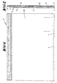
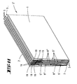
- die erfindungsgemäße Schriftgut-Sammelmappe in Ansicht, gemäß erstem Ausführungsbeispiel,
- Fig. 2
- dieselbe in Seitenansicht,
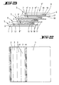
- Fig. 3
- einen den Boden und die Tasche der Sammelmappe bildenden Zuschnitt,
- Fig. 4
- einen den Deckel und die Stecklasche bringenden Zuschnitt der Sammelmappe,
- Fig. 5
- die komplettierte Schriftgut-Sammelmappe, aufgeschlagen, mit minimal freigelegter Breite ihres Rückens,
- Fig. 6
- eine der Fig. 5 entsprechende Darstellung bei maximal freigelegter Breite des Rückens,
- Fig. 7
- eine Variante des den Boden und die Tasche bildenden Zuschnitts, auch einsetzbar als Bindeglied zum Aufbau einer Mehrfach-Schriftgut-Sammelmappe,
- Fig. 8
- ein weitergebildeter, Decke und Stecklasche plus Stopp bringender Zuschnitt,
- Fig. 9
- ein ebenfalls Decke, Stecklasche und Stopp bringender Zuschnitt, anwendbar im Zusammenhang mit dem Zuschnitt gemäß Fig. 7,
- Fig. 10
- einen der Fig. 7 entsprechenden Zwischenzuschnitt als taschenbildendes Verbindungsteil für die Mehrfach-Schriftgut-Sammelmappe,
- Fig. 11
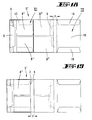
- eine zusammengestellte Mehrfach-Schriftgut-Sammelmappe in perspektivischer Darstellung, geschlossen, als zweites Ausführungsbeispiel,
- Fig. 12
- dieselbe mit Einsicht in die aufgeschlagene erste Sammelmappe der Mehrfach-Schriftgut-Sammelmappe, und zwar in rückenmäßig ungedehntem Zustand,
- Fig. 13
- dieselbe in Dehnstellung,
- Fig. 14
- die Mehrfach-Schriftgut-Sammelmappe mit Einsicht in die zweite aufgeschlagene Sammelmappe, ungedehnt,
- Fig. 15
- dieselbe in Dehnstellung,
- Fig. 16
- die Mehrfach-Schriftgut-Sammelmappe mit Einsicht in die dritte aufgeschlagene Sammelmappe, ungedehnt,
- Fig. 17
- dieselbe in Dehnstellung,
- Fig. 18
- die Mehrfach-Schriftgut-Sammelmappe mit Einsicht in die vierte aufgeschlagene Sammelmappe,ungedehnt,
- Fig. 19
- dieselbe in Dehnstellung,
- Fig. 20
- die Mehrfach-Schriftgut-Sammelmappe mit Einsicht in die fünfte aufgeschlagene Sammelmappe,
- Fig. 21
- dieselbe in geschlossenem Zustand, und zwar gegen die Rückseite gesehen,
- Fig. 22
- eine Ansicht der Mehrfach-Schriftgut-Sammelmappe, ungefüllt und mit zufolge maximaler Freigabe der Dehnung geschindelter Struktur,
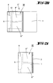
- Fig. 23
- eine weitestgehend schematisierte Seitenansicht hierzu, die Funktion der Verbindungsteile verdeutlichend,
- Fig. 24
- eine gleiche Seitenansicht, wobei eine der gebündelten Schriftgut-Sammelmappen im Rücken zufolge wachsenden Anfüllens in den Dehnungszustand überführt ist und
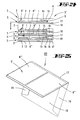
- Fig. 25
- in perspektivischer Darstellung das von dem Zwischenzuschnitt gebildete Verbindungsteil alleine.
- Fig. 1
- the document folder according to the invention in view, according to the first embodiment,
- Fig. 2
- the same in side view,
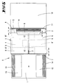
- Fig. 3
- a blank forming the bottom and the pocket of the binder,
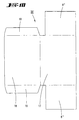
- Fig. 4
- a blank of the binder that brings the lid and the tab,
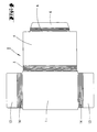
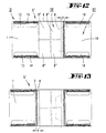
- Fig. 5
- the completed document folder, opened, with a minimally exposed width of its back,
- Fig. 6
- 5 corresponding representation with the maximum exposed width of the back,
- Fig. 7
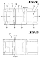
- a variant of the cut forming the base and the pocket, can also be used as a link to build up a multiple document folder,
- Fig. 8
- a further-developed blank, blanket and flap plus stop,
- Fig. 9
- a blank, plug-in flap and stop, also applicable in connection with the blank according to FIG. 7,
- Fig. 10
- 7 an intermediate blank corresponding to FIG. 7 as a pocket-forming connecting part for the multiple document folder,
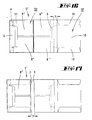
- Fig. 11
- a compiled multiple document folder in perspective, closed, as a second embodiment,
- Fig. 12
- the same with an insight into the opened first folder of the multiple document folder, and that in the back unstretched state,
- Fig. 13
- same in stretched position,
- Fig. 14
- the multiple document folder with a view of the second open folder, unstretched,
- Fig. 15
- same in stretched position,
- Fig. 16
- the multiple document folder with a view of the third opened folder, unstretched,
- Fig. 17
- same in stretched position,
- Fig. 18
- the multiple document folder with view of the fourth open folder, unstretched,
- Fig. 19
- same in stretched position,
- Fig. 20
- the multiple document folder with an insight into the fifth open folder,
- Fig. 21
- the same in the closed state, as seen against the back,
- Fig. 22
- a view of the multiple document binder, unfilled and with shingled structure according to maximum release of the stretch,
- Fig. 23
- a largely schematic side view of this, illustrating the function of the connecting parts,
- Fig. 24
- a same side view, wherein one of the bundled document folders in the back is transferred to the stretched state due to growing filling and
- Fig. 25
- in a perspective view, the connecting part formed by the intermediate blank alone.
Der mappenartig auf- und zuklappbare Loseblattsammler,
nachstehend durchweg bezeichnet als Schriftgut-Sammelmappe
S umfaßt einen Deckel 1 und einen Boden 2. Beide
genannten Teile sind etwa gleicher Flächengröße und
weisen rechteckigen Grundriß auf. Sie bestehen vorzugsweise
aus Kartonmaterial; es kann sich aber auch um
Kunststoffolie oder dünneres Papier handeln.The loose leaf collector that can be opened and closed like a folder,
hereinafter referred to consistently as a document folder
S includes a
Deckel 1 und Boden 2 stehen über einen Rücken 3 in
Verbindung. Der läßt sich breitenmäßig im Hinblick auf
zunehmende oder abnehmende Stapelhöhen des Schriftgutes
bzw. Ablagegutes verändern. Deckel 1 und Boden 2 bleiben
dabei flächenmäßig erhalten. Den entsprechenden
Dehnungsvorrat des Rückens 3 hält eine an ihn anschließende
Stecklasche 4 bereit. Letztere führt sich als
sogenannter Stopper in einer Tasche 5 der dazu zumindest
zweitteilig ausgebildete Schriftgut-Sammelmappe S.
Der Auszug-Hub der Stecklasche 4 liegt beispielsweise
bei drei cm. Bezüglich der Tasche 5 kann es sich jedoch
auch um einen separaten Flachschlauchabschnitt handeln.
Es reicht u.U. schon ein C-Profil aus. Die Endbereiche
der C-Schenkel formen nutartige Schächte. Solche Taschen
können durch Heften, Kleben oder dergleichen fest
zugeordnet werden.
Deckel 1, Rücken 3 und Stecklasche 4 bestehen aus einem
gemeinsamen ersten Zuschnitt I im wesentlichen T-förmigen
Gestalt. Der ist in Fig. 4 isoliert dargestellt. In
der genannten Reihenfolge der Funktionsteile 1, 3 und 4
schließt endlich ein Umschlagabschnitt 6 an. Der fungiert
als einen Verschiebeweg x begrenzender Anschlag
A, also als sogenannter Stopper. In beiden Endstellungen
liegt eine definierte Verschieberichtung vor. Zumindest
ist aber der Auszug gesperrt. Der in Fig. 5 dargestellte
maximale Verschiebeweg x zwischen Tasche 5 und
Stecklasche 4 entspricht im wesentlichen der gewählten
maximal erreichbaren bzw. nutzbaren Breite y des Rükkens
3. Wie Fig. 6 entnehmbar, ist der Anschlag A von
dem Grund der Falzfuge des in Richtung des Rückens 3
umgelegten Umschlagabschnitts 6 gebildet. Die Verschieberichtungen
(hin und zurück) sind durch Pfeile angedeutet.
Den entsprechenden Gegenhalt bekommt diese Auszugbegrenzungsvorrichtung
durch die erwähnte Tasche 5, welche
Bestandteil eines zweiten, mit II bezeichneten Zuschnitts
ist, beispielsweise dargestellt in Fig. 3.
Sein Umschlagabschnitt 6 übergreift die Tasche 5 oberseitig
(sh. Fig. 6). Dieser Übergriff ist auch dann
noch gegeben, wenn, wie in Fig. 5 veranschaulicht, die
gesamte Breite y des Rückens 3 in die Tasche 5 eingefahren
ist, so daß der Rücken 3 dort praktisch nur noch
einen deckelnahen Klappfalz 7 bietet. Der Übergriff ist
mit z bezeichnet (vergl. Fig. 5). Rücken 3 und Umschlagabschnitt
6 können, wie ersichtlich, eng parallel gefalzt
sein.This pull-out limitation device receives the appropriate counter support
through the mentioned
Eine baulich besonders einfache Lösung besteht darin,
die Stecklasche 4 zu verschmälern und als Parallelstreifen-Zunge
in einem oder besser zwei Querschlitzen des
Bodens 2 verschieblich zu führen. Quer meint: quer zur
Verschieberichtung x. Nach dem Einfädeln wird das freie
Ende der Stecklasche 4, der Umschlagabschnitt 6 also,
über die rückenabgewandte Schmalseite des betreffenden
Querschlitzes gefaltet. So entsteht auch hier ein wirksamer
Stopper. Der Umschlagabschnitt 6 kann nach auswärts
durchgefaltet werden. Diese Variante ist nicht
dargestellt, da leicht vorstellbar. Man kann so bezüglich
des Bodens 2 im gängigen Formart bleiben, d.h. beispielsweise
DIN A 4. Die Tasche 5 ist hier besonders
materialsparend integriert. Generell kann die Tasche 5
auch wahlweise am Deckel 1 oder am Boden 2 ausgebildet
sein.A structurally particularly simple solution consists in
narrow the
Auch der zweite Zuschnitt II ist im Grunde T-förmigen
Umrisses, wobei der T-Steg flächenmäßig den erwähnten
Boden 2 bildet und die dortigen T-Schenkel Klappfahnen
8 formen, die quer zur Verschieberichtung der Stecklasche
4 in das Innere der Mappe eingeschlagen sind. Sie
enden dort Stirnseite gegen Stirnseite gerichtet.
Statt, wie dargestellt und bevorzugt, kann die Tasche 5
aber auch aus nur einer vom Boden 2 ausgehenden Klappfahne
8 erzeugt sein. Die diesbezüglichen Klappfalzen
tragen das Bezugszeichen 9. Die rückenferne Schmalseite
der Klappfahnen 8 fungieren als Gegenanschlag G zu A.The second blank II is also basically T-shaped
Outline, with the T-bridge in terms of area mentioned
Wie Fig. 3 und auch beispielsweise Fig. 6 entnehmbar,
setzt sich der Boden 2 in der Verschieberichtung der
Stecklasche 4 noch in eine Einschlagwand 10 fort,
gleichsam den T-Steg verlängernd. Die Einschlagwand 10
setzt an einer Falzlinie 11 des Bodens 2 an. Deckel 1,
Boden 2 und Einschlagwand 10 sind etwa flächengleich.3 and also, for example, FIG. 6,
the
Um die Breite y des Rückens 3 beispielsweise auch stufenweise
variieren zu können, sind sowohl der Rücken 3
als auch der Umschlagabschnitt 6 durch aus den Zeichnungen
ersichtliche, eng benachbarte Falzungen vorbereitet,
so daß die rückenabgewandte Schmalseite der Klappfahne
8 bzw. der Klappfahnen 8 auch demgegenüber als
Gegenanschlag G des Anschlages A in Wirkung treten.In steps of the width y of the
Der Gegenanschlag G kann auch in einem Bereich der
Tasche 5 ausgebildet sein, der dem Rücken 3 näherliegt.
Hierzu brauchen die Klappfahnen 8 bloß entsprechend
zurückgeschnitten zu werden. Hierüber kann man die den
Gegenanschlag G bildete Schmalseite mehr in Richtung
des Rückens 3 verlegen. Außerdem ist eine gestufte
Anordnung von Gegenanschlägen G möglich, indem man die
Klappfahnen 8 abstandsweise schlitzt. Ein solcher
Schlitz ist beispielsweise in Fig. 6 wiedergegeben und
mit 12 bezeichnet. Die auf diese Weise unter Ausbildung
von Teil-Klappfahnen 8', 8' längs geteilte Klappfahne 8
könnte auch gestufte, leiterartig angeordnete Gegenanschläge
schaffen. Fig. 5 zeigt in strichpunktierter
Linienart eine zweite Variante der Teil-Klappfahnen 8',
und zwar wechselweise gegenläufig gerichtet und einander
seitlich deutlich überlappend.The counter stop G can also be in a range of
Solche Klappfahnen 8 bzw. 8' lassen sich ferner als
schmale Leisten realisieren, beispielsweise innenseitig
mit einem Flächenverschluß bestückt. Die Randpartie der
Stecklasche 4 würde dabei den Gegenverschluß tragen. Gedacht
ist hier an einen sogenannten Klettverschluß.Such
Der variierbare Verstellbereich kann in vorteilhafter
Weise durch die erwähnte Einschlagwand 10 abgedeckt
werden, so daß das nicht dargestellte Schriftgut bzw.
Ablagegut demgegenüber abgeteilt aufgenommen wird. The variable adjustment range can be advantageous
Way covered by the
Im Interesse einer seitlichen Lagesicherung des Schriftgutes
der im Querformat genutzten Sammelmappe S dienen
einschlagbare Tragleisten 13. Die gehen über Klappfalze
14 in den Deckel 1 über bzw. gehen von diesem aus. Der
deckelrandseitige Ansatz der Tragleisten 13 geht ab
besagtem Klappfalz 14 in eine Falzung über, so daß auch
diese Tragleisten 13 in bezug auf die Stapelhöhe der
Schriftgutsammlung mitwachsen bzw. wieder reduziert
werden können.In the interest of securing the documents on the side
the folder S used in landscape format
foldable support strips 13. They go over folding seams
14 in the
Die Mehrfach-Schrifgut-Sammelmappe S', das zweite
Ausführungsbeispiel verkörpernd (vergl. z.B. Fig.11),
ist prinzipiell gleichen Aufbaues. Die Bezugsziffern
sind, zum Teil ohne textliche Wiederholungen, sinngemäß
angewandt. Dort sind einzelne Schriftgut-Sammelmappen S
zu einer Art Dehnmappe addiert, dazu übereinanderliegend
zusammengefaßt, wobei ein aus vielen Rücken 3
erzielbarer Gesamtrücken vorliegt. Die Übereinanderanordnung
geht deutlich aus den Fig. 22 bis 24 hervor.
Neben der auch hier vorliegenden, oben eingehend erörterten
anschlagbegrenzten Verschiebbarkeit sind die
einzelnen Schriftgut-Sammelmappen S über ein Verbindungsteil
aneinander gefesselt. Es sei auf Fig. 11
verwiesen.The multiple scripts folder S ', the second
Embodiment embodiment (see e.g. Fig. 11),
is basically the same structure. The reference numbers
are, in part without repeated text, analogous
applied. There are individual document folders S
added to a kind of expansion folder, lying on top of each other
summarized, one of
Bezüglich des Verbindungsteils handelt es sich um einen taschenbildenden Zwischenzuschnitt III, wie er sich hauptsächlich aus Fig. 10 ergibt und in Abwandlung auch aus Fig. 7. In zur Montage vorbereiteter Faltstellung geht er (III) in perspektivischer Darstellung aus Fig. 25 hervor.Regarding the connecting part, it is a pocket-forming intermediate cut III as it is mainly results from Fig. 10 and also in a modification from Fig. 7. In the folded position prepared for assembly he goes (III) in perspective from Fig. 25 out.
Seine Tasche, hier bezeichnet mit 5', besteht aus zwei
Klappfahnen 8'', welche quer zur Verschieberichtung
(vergl. Pfeile in den Fig. 5 und 6) gegeneinander gefaltet
sind. Diese Klappfahnen 8'', 8'' ergeben sich aus
der auch hier entsprechend T-förmigen Gestalt des Zwischenzuschnitts
III. So entsteht eine Art Schlauchabschnitt
bzw. durchgehend steckoffener Tasche 5'. Die
nimmt den Boden 2 einer ersten Schriftgut-Sammelmappe S
und den Deckel 1 einer zweiten Schriftgut-Sammelmappe S
auf. Diese Teile sind gemeinsam oder unabhängig voneinander
im Schlauchabschnitt respektive in der Tasche 5'
anschlag- bzw. auszugsbegrenzt verschieblich geführt.
Dabei setzen sich hier die durch die Tasche 5' geführten
und anschlagbegrenzt darin verlagerbaren Böden 2
und Deckel 1 je in einen Umschlagabschnitt 15 bzw. 16
fort. Letztere erfüllen die Funktion des Umschlagabschnitts
6 und die der Fesselung der Sammelmappen S
aneinander. Sie nehmen zudem bei maximal freigegebener
Breite y des jeweiligen Rückens 3 eine eng angeschmiegte,
rittlingsartige Lage ein (vergl. Fig. 23). Der vom
Boden 2 herkommende Umschlagabschnitt 15 tritt mit
seinem Falzgrund als Gegenanschlag G gegen den von der
korrespondierenden Schmalseite der Klappfahnen 8'' der
Tasche 5' gebildeten Anschlag A. Bei dem nach links
gehenden Ausschub eines Sammlers S bleiben die Umschlagabschnitte
15, 16 noch in einem Restabschnitt in Überlappung.
Ein Trennen der so zusammengefaßten Schriftgut-Sammelmappen
S ist nur unter Zerstörung der entsprechenden
Verlagerungsbegrenzungsmittel möglich. ,His pocket, here marked 5 ', consists of two
Folding flags 8 '', which are transverse to the direction of displacement
(see arrows in Figs. 5 and 6) folded against each other
are. These
Wie Fig. 23 ebenfalls entnehmbar, weist der Zwischenzuschnitt
III eine über seinen Rücken 17 hinausgehende
Einschlagwand 18 auf. Die besitzt umfaltbare, in der
Darstellung untergeschlagene Tragleisten 19, welche
eine Aufgabe übernehmen, wie sie im Hinblick auf die
Tragleisen 13 des Deckels 1 erläutert ist. As can also be seen in FIG. 23, the intermediate blank has
III a going beyond his
Fig. 24 zeigt eine der Schriftgut-Sammelmappen S mit in eine größere Breite y überführtem, den Deckel-zu-Boden-Lagenabstand vergrößernden Rücken 3. Hierdurch liegt ein der diesbezüglichen Stapelhöhe im wesentlichen gerecht werdender Aufnahmegrad dieser Sammelmappe S vor.Fig. 24 shows one of the document folders S with in a larger width y transferred the lid-to-floor layer spacing enlarging back 3. Hereby lies one of the relevant stack heights essentially fair level of acceptance of this folder S before.
Ab Fig. 12 ergibt sich eine Aufklappstudie vom anfänglichen
Aufklappen der dortigen Mehrfach-Schriftgut-Sammelmappe
S' bis hin zum Ende bzw. Schließen dieser Sammelmappe
(Fig. 21). Es kehren darin die oben erläuterten
Elemente wieder. Die Bezugsziffern sind textentsprechend
angewandt. Die Fig. 12, 14, 16, 18 zeigen die
minimale Nutzbreite des Rückens 3, eben gerade im Sinne
der Schaffung der Klappfalze 7, welche Breite bei nur
schwach angefüllten Loseblattsammlern auftritt bzw.
genügt. Die Fig. 13, 15, 17 und 19 geben dagegen die
maximale Breite y des Rückens 3 an, wobei es natürlich
verständlich ist, daß durch Gebrauch der leiterartigen
Anschläge A eine noch weit größere Verbreiterung des
Rückens 3 erreicht werden kann, dies unter noch weiterer
Nutzung der recht langen Stecklasche 4. Aufgeschlagen
sind in sämtlichen Darstellungen der Fig. 12 bis 19
auch noch die jeweils anschließenden Einschlagwände 10
bzw. 18.From Fig. 12 there is an opening study of the initial one
Unfold the multiple document folder there
S 'to the end or closing of this folder
(Fig. 21). It returns the ones explained above
Elements again. The reference numbers correspond to the text
applied. 12, 14, 16, 18 show the
minimal useful width of the
Fig. 14 zeigt die Besetzung beider je einen Anschlag A
bildender Teil-Klappfahnen 8'', 8'', wobei das
verhakungsmäßig dem Rücken 3 näherliegende Element in
bezug auf seinen Umschlagabschnitt längen- bzw. umrißmäßig
entsprechend angepaßt ist. Dieses Element ergibt
sich aus Fig. 9.Fig. 14 shows the occupation of both a stop A.
Partial folding flags 8 '', 8 '', the
hooking element closer to the
Bei diesem Ausführungsbeispiel kann auch die oben erläuterte Zungenverankerung greifen, ferner im Sinne eines Schubers, der die Teile zusammenhält. In this embodiment, the one explained above can also be used Tongue anchorage grip, further in the sense of a Schubers, who holds the parts together.
Alle offenbarten Merkmale sind erfindungswesentlich. In die Offenbarung der Anmeldung wir hiermit auch der Offenbarungsinhalt der zugehörigen/beigefügten Prioritätsunterlagen (Abschrift der Voranmeldung) vollinhaltlich mit einbezogen, auch zu dem Zweck, Merkmale dieser Unterlagen in Ansprüche vorliegender Anmeldung mit aufzunehmen.All the features disclosed are essential to the invention. In the disclosure of the application is hereby also the Disclosure content of the associated / attached priority documents (Copy of the pre-registration) in full included, also for the purpose, characteristics of this Documents in claims of the present registration with to record.
Claims (14)
- Folder (S) for papers, with a cover (1) and a base (2) which are joined together by a back (3), the back (3) being variable in width (x) in adaptation to a stack height of the collection of papers, for which purpose the back (3) continues on the base side into an insertion tongue (4) which is slidable in a pocket (5) joined to the base (2), characterised in that the insertion tongue (4) is slidable in the pocket (5) to an extent limited by a stop.
- Folder for papers according to claim 1, characterised in that the insertion tongue (4) comprises a turn-over section (6) for forming the stop (A).
- Folder for papers according to one or more of the preceding claims, characterised in that the turn-over section (6) overlaps the pocket (5) on the upper side.
- Folder for papers according to one or more of the preceding claims, characterised in that the pocket (5) is formed from a folding flap (8) joined to the base (2).
- Folder for papers according to one or more of the preceding claims, characterised in that the pocket (5) is formed from two folding flaps (8) joined to the base (2) in opposite directions.
- Folder for papers according to one or more of the preceding claims, characterised in that the turn-over section (6) is prepared by crimping over to vary the length.
- Folder for papers according to one or more of the preceding claims, characterised in that a narrow side of the folding flap (8) that faces away from the back cooperates with the turn-over section (6) as a counterstop (G).
- Folder for papers according to one or more of the preceding claims, characterised in that the folding flap (8) is longitudinally divided, forming partial folding flaps (8', 8'), to vary the counterstop (G).
- Folder for papers according to one or more of the preceding claims, characterised in that the base (2) facing away from the back continues into a fold-in wall (10) completely or partially overlapping the pocket (5).
- Multiple folder (S') for papers, characterised by folders (S) arranged one above the other according to one or more of the preceding claims 1 to 9, which are joined as to be slidable relative to one another to a limited extent in one direction only.
- Multiple folder (S') for papers according to claim 10, characterised by a pocket (5') joining the base (2) of a first folder (S) and the cover (1) of a second folder (S) etc. so as to be slidable to a limited extent.
- Multiple folder (S') for papers according to one or more of the preceding claims, characterised in that the pocket (5') is formed by an intermediate blank (III) as a joining portion comprising the folding flap or flaps (8'', 8''), and the covers (1) and bases (2) linked together in each case by the pocket (5') comprise the turn-over sections (15 or 16).
- Multiple folder (S') for papers according to one or more of the preceding claims, characterised in that the intermediate blank (III) too comprises a fold-in wall (18) extending beyond its back (17).
- Multiple folder (S') for papers according to one or more of the preceding claims, characterised in that the fold-in wall (18) has supporting strips (19) that can be folded over transversely to a path of sliding (x) of the insertion tongue (4) or the like.
Applications Claiming Priority (3)
| Application Number | Priority Date | Filing Date | Title |
|---|---|---|---|
| DE19620506 | 1996-05-22 | ||
| DE19620506A DE19620506B4 (en) | 1996-05-22 | 1996-05-22 | Folder for papers |
| PCT/EP1997/002515 WO1997044199A1 (en) | 1996-05-22 | 1997-05-16 | Folder for papers |
Publications (3)
| Publication Number | Publication Date |
|---|---|
| EP0907518A1 EP0907518A1 (en) | 1999-04-14 |
| EP0907518B1 true EP0907518B1 (en) | 2000-04-26 |
| EP0907518B2 EP0907518B2 (en) | 2006-06-14 |
Family
ID=7794946
Family Applications (1)
| Application Number | Title | Priority Date | Filing Date |
|---|---|---|---|
| EP97923918A Expired - Lifetime EP0907518B2 (en) | 1996-05-22 | 1997-05-16 | Folder for papers |
Country Status (8)
| Country | Link |
|---|---|
| US (1) | US6286752B1 (en) |
| EP (1) | EP0907518B2 (en) |
| AT (1) | ATE192090T1 (en) |
| AU (1) | AU711739B2 (en) |
| CA (1) | CA2255849A1 (en) |
| DE (3) | DE19620506B4 (en) |
| NZ (1) | NZ332936A (en) |
| WO (1) | WO1997044199A1 (en) |
Families Citing this family (10)
| Publication number | Priority date | Publication date | Assignee | Title |
|---|---|---|---|---|
| US6679418B1 (en) * | 2001-01-18 | 2004-01-20 | Productive Environments Inc. | Integral self sectioning file folder |
| US6817516B2 (en) * | 2001-08-16 | 2004-11-16 | Vonnida Mark A. | Ballot secrecy sleeve |
| WO2003095229A1 (en) * | 2002-05-14 | 2003-11-20 | Nozala, S.A. De C.V. | Device for securing the contents of folders |
| US20040017074A1 (en) * | 2002-07-25 | 2004-01-29 | Mcmorrow Patrice L. | Personal information recording system |
| ITBO20080350A1 (en) * | 2008-06-04 | 2009-12-05 | Frati E Livi S R L | VARIABLE OVERALL COLLECTOR. |
| DE102008055493A1 (en) | 2008-12-09 | 2010-06-10 | Uwe Freund | Extensively adjustable elongating binder for assembling office articles, has two portions moving into one another, slipcase bag and inner part, where slipcase bag consists of upper part and lower part |
| US9174115B2 (en) * | 2011-03-29 | 2015-11-03 | Michael Lee Vaughan | Convertible item for folding into a play field |
| DE102011053061A1 (en) * | 2011-07-16 | 2013-01-17 | Egon Heimann | Customizable envelope wallet |
| US9902189B2 (en) | 2012-12-02 | 2018-02-27 | Smead Manufacturing Company | Vertical pocket folder |
| US9346588B2 (en) * | 2012-12-02 | 2016-05-24 | Smead Manufacturing Company | Vertical pocket folder |
Family Cites Families (11)
| Publication number | Priority date | Publication date | Assignee | Title |
|---|---|---|---|---|
| DE382179C (en) * | 1923-09-29 | Max O Dukas | Folder or the like with adjustable back part bent from the lids | |
| US984482A (en) * | 1910-09-08 | 1911-02-14 | David A Howell | Filing-folder. |
| DE671229C (en) * | 1937-02-07 | 1939-02-03 | Willy Salchow | Procedure and execution form of the procedure for book-like joining of loose sheets |
| US2252177A (en) * | 1938-05-10 | 1941-08-12 | Heyer William Carl | Wallet |
| DE3028799A1 (en) * | 1980-07-30 | 1982-03-04 | Mappei-Organisationsmittel Gmbh, 5600 Wuppertal | Folding box for sheet storage - is made from carton sheet cut=out with one width side wall continued and folded into box interior round flaps of side walls |
| US4331290A (en) * | 1980-09-18 | 1982-05-25 | Champion International Corporation | Multiple pocket, expandable envelope, and blank and method for forming same |
| FR2586617B1 (en) * | 1985-09-04 | 1989-03-03 | Viquel Gerard | CLASSIFICATION FILE WITH ADJUSTABLE HEIGHT AND WIDTH |
| FR2615451B1 (en) * | 1987-05-21 | 1992-02-28 | Chevalerias | IMPROVED EXTENSIBLE FILER |
| IT1234751B (en) | 1989-02-10 | 1992-05-26 | Rossignoli Michele E C | HYDROPRESSOSTATIC VALVE PARTICULARLY FOR HEATING SYSTEMS EQUIPPED WITH DOMESTIC WATER PRODUCTION. |
| US5803250A (en) * | 1993-11-19 | 1998-09-08 | Mori; Takanori | Case for disk-type recording medium |
| US5797630A (en) * | 1996-01-16 | 1998-08-25 | Direct Business Technologies, Inc. | Method and system for generating, storing and managing records |
-
1996
- 1996-05-22 DE DE19620506A patent/DE19620506B4/en not_active Expired - Fee Related
-
1997
- 1997-05-16 US US09/194,483 patent/US6286752B1/en not_active Expired - Fee Related
- 1997-05-16 AT AT97923918T patent/ATE192090T1/en active
- 1997-05-16 NZ NZ332936A patent/NZ332936A/en unknown
- 1997-05-16 CA CA002255849A patent/CA2255849A1/en not_active Abandoned
- 1997-05-16 DE DE59701524T patent/DE59701524D1/en not_active Expired - Lifetime
- 1997-05-16 WO PCT/EP1997/002515 patent/WO1997044199A1/en not_active Ceased
- 1997-05-16 AU AU29564/97A patent/AU711739B2/en not_active Ceased
- 1997-05-16 EP EP97923918A patent/EP0907518B2/en not_active Expired - Lifetime
- 1997-05-16 DE DE29723588U patent/DE29723588U1/en not_active Expired - Lifetime
Also Published As
| Publication number | Publication date |
|---|---|
| CA2255849A1 (en) | 1997-11-27 |
| DE19620506B4 (en) | 2007-05-03 |
| EP0907518B2 (en) | 2006-06-14 |
| AU2956497A (en) | 1997-12-09 |
| DE19620506A1 (en) | 1997-11-27 |
| AU711739B2 (en) | 1999-10-21 |
| EP0907518A1 (en) | 1999-04-14 |
| DE59701524D1 (en) | 2000-05-31 |
| DE29723588U1 (en) | 1998-10-22 |
| ATE192090T1 (en) | 2000-05-15 |
| WO1997044199A1 (en) | 1997-11-27 |
| NZ332936A (en) | 1999-04-29 |
| US6286752B1 (en) | 2001-09-11 |
Similar Documents
| Publication | Publication Date | Title |
|---|---|---|
| EP0814044B1 (en) | Method for the production of multi-page printed products consisting of folded sheets | |
| DE2537111A1 (en) | PACK WITH SLIDER ACTUATED CAP CONSTRUCTION | |
| EP0907518B1 (en) | Folder for papers | |
| DE1815376A1 (en) | Collapsible file folder | |
| EP0499152B1 (en) | Folder, or the like | |
| DE913158C (en) | Cut for a folding box | |
| EP2776252B1 (en) | Method for producing printed products consisting of at least three sub-products | |
| EP0853551A1 (en) | Note pad | |
| AT2520U1 (en) | WRITING CARDBOARD | |
| DE8315844U1 (en) | Packaging for cigarette papers | |
| DE3144529C2 (en) | a book | |
| DE69905440T2 (en) | Package insert made of paper, packaging consisting of a case with such a package insert, arrangement consisting of the packaging and its contents, method for producing the package insert | |
| DE2209280B2 (en) | Box formed from a folding blank for storing documents | |
| DE20113543U1 (en) | Folder for filing sheets | |
| DE3143614C2 (en) | Binder | |
| DE728172C (en) | Hanging pocket for storing index cards or similar documents | |
| DE2119646C3 (en) | Book-shaped foldable filing folder | |
| DE2140219C3 (en) | Folder for filing documents | |
| DE3207194C2 (en) | Binder | |
| DE9401631U1 (en) | Clip-in filing strips | |
| DE9406082U1 (en) | folder | |
| DE202005009508U1 (en) | Folder for holding documents comprises a front part bound to a rear part with an insertion section interacting with a covering section of the front part | |
| DE19910726A1 (en) | Collecting tray for waste paper | |
| DE6920235U (en) | WRAPPING FOR LOOSE OR BUNDLED DOCUMENTS | |
| DE29501650U1 (en) | Newspaper with sheets of paper perforated along its fold |
Legal Events
| Date | Code | Title | Description |
|---|---|---|---|
| PUAI | Public reference made under article 153(3) epc to a published international application that has entered the european phase |
Free format text: ORIGINAL CODE: 0009012 |
|
| 17P | Request for examination filed |
Effective date: 19981105 |
|
| AK | Designated contracting states |
Kind code of ref document: A1 Designated state(s): AT CH DE FR GB LI NL |
|
| GRAG | Despatch of communication of intention to grant |
Free format text: ORIGINAL CODE: EPIDOS AGRA |
|
| GRAG | Despatch of communication of intention to grant |
Free format text: ORIGINAL CODE: EPIDOS AGRA |
|
| 17Q | First examination report despatched |
Effective date: 19990623 |
|
| GRAG | Despatch of communication of intention to grant |
Free format text: ORIGINAL CODE: EPIDOS AGRA |
|
| GRAH | Despatch of communication of intention to grant a patent |
Free format text: ORIGINAL CODE: EPIDOS IGRA |
|
| GRAH | Despatch of communication of intention to grant a patent |
Free format text: ORIGINAL CODE: EPIDOS IGRA |
|
| GRAA | (expected) grant |
Free format text: ORIGINAL CODE: 0009210 |
|
| AK | Designated contracting states |
Kind code of ref document: B1 Designated state(s): AT CH DE FR GB LI NL |
|
| REF | Corresponds to: |
Ref document number: 192090 Country of ref document: AT Date of ref document: 20000515 Kind code of ref document: T |
|
| REG | Reference to a national code |
Ref country code: CH Ref legal event code: NV Representative=s name: R. A. EGLI & CO. PATENTANWAELTE Ref country code: CH Ref legal event code: EP |
|
| ET | Fr: translation filed | ||
| GBT | Gb: translation of ep patent filed (gb section 77(6)(a)/1977) |
Effective date: 20000426 |
|
| REF | Corresponds to: |
Ref document number: 59701524 Country of ref document: DE Date of ref document: 20000531 |
|
| REG | Reference to a national code |
Ref country code: CH Ref legal event code: PUE Owner name: MAPPEI-ORGANISATIONSMITTEL GMBH TRANSFER- MAPPEI-O |
|
| REG | Reference to a national code |
Ref country code: CH Ref legal event code: NV Representative=s name: R. A. EGLI & CO. PATENTANWAELTE |
|
| NLS | Nl: assignments of ep-patents |
Owner name: MAPPEI-ORGANISATIONSMITTEL GMBH & CO. KG. |
|
| PLBQ | Unpublished change to opponent data |
Free format text: ORIGINAL CODE: EPIDOS OPPO |
|
| PLBI | Opposition filed |
Free format text: ORIGINAL CODE: 0009260 |
|
| PLBF | Reply of patent proprietor to notice(s) of opposition |
Free format text: ORIGINAL CODE: EPIDOS OBSO |
|
| 26 | Opposition filed |
Opponent name: ORGAPLAN BUEROORGANISATIONSMITTELGESELLSCHAFT M.B. Effective date: 20010122 |
|
| REG | Reference to a national code |
Ref country code: FR Ref legal event code: CD |
|
| NLR1 | Nl: opposition has been filed with the epo |
Opponent name: ORGAPLAN BUEROORGANISATIONSMITTELGESELLSCHAFT M.B. |
|
| PLBF | Reply of patent proprietor to notice(s) of opposition |
Free format text: ORIGINAL CODE: EPIDOS OBSO |
|
| REG | Reference to a national code |
Ref country code: GB Ref legal event code: IF02 |
|
| PLAW | Interlocutory decision in opposition |
Free format text: ORIGINAL CODE: EPIDOS IDOP |
|
| APBP | Date of receipt of notice of appeal recorded |
Free format text: ORIGINAL CODE: EPIDOSNNOA2O |
|
| APBQ | Date of receipt of statement of grounds of appeal recorded |
Free format text: ORIGINAL CODE: EPIDOSNNOA3O |
|
| APAA | Appeal reference recorded |
Free format text: ORIGINAL CODE: EPIDOS REFN |
|
| APAH | Appeal reference modified |
Free format text: ORIGINAL CODE: EPIDOSCREFNO |
|
| APBU | Appeal procedure closed |
Free format text: ORIGINAL CODE: EPIDOSNNOA9O |
|
| PUAH | Patent maintained in amended form |
Free format text: ORIGINAL CODE: 0009272 |
|
| STAA | Information on the status of an ep patent application or granted ep patent |
Free format text: STATUS: PATENT MAINTAINED AS AMENDED |
|
| 27A | Patent maintained in amended form |
Effective date: 20060614 |
|
| AK | Designated contracting states |
Kind code of ref document: B2 Designated state(s): AT CH DE FR GB LI NL |
|
| REG | Reference to a national code |
Ref country code: CH Ref legal event code: AEN Free format text: AUFRECHTERHALTUNG DES PATENTES IN GEAENDERTER FORM |
|
| NLR2 | Nl: decision of opposition |
Effective date: 20060614 |
|
| GBT | Gb: translation of ep patent filed (gb section 77(6)(a)/1977) |
Effective date: 20060712 |
|
| NLR3 | Nl: receipt of modified translations in the netherlands language after an opposition procedure | ||
| ET3 | Fr: translation filed ** decision concerning opposition | ||
| REG | Reference to a national code |
Ref country code: FR Ref legal event code: PLFP Year of fee payment: 20 |
|
| PGFP | Annual fee paid to national office [announced via postgrant information from national office to epo] |
Ref country code: NL Payment date: 20160513 Year of fee payment: 20 |
|
| PGFP | Annual fee paid to national office [announced via postgrant information from national office to epo] |
Ref country code: DE Payment date: 20160519 Year of fee payment: 20 Ref country code: CH Payment date: 20160517 Year of fee payment: 20 Ref country code: GB Payment date: 20160517 Year of fee payment: 20 |
|
| PGFP | Annual fee paid to national office [announced via postgrant information from national office to epo] |
Ref country code: FR Payment date: 20160518 Year of fee payment: 20 Ref country code: AT Payment date: 20160513 Year of fee payment: 20 |
|
| REG | Reference to a national code |
Ref country code: DE Ref legal event code: R071 Ref document number: 59701524 Country of ref document: DE |
|
| REG | Reference to a national code |
Ref country code: NL Ref legal event code: MK Effective date: 20170515 |
|
| REG | Reference to a national code |
Ref country code: CH Ref legal event code: PL |
|
| REG | Reference to a national code |
Ref country code: GB Ref legal event code: PE20 Expiry date: 20170515 |
|
| REG | Reference to a national code |
Ref country code: AT Ref legal event code: MK07 Ref document number: 192090 Country of ref document: AT Kind code of ref document: T Effective date: 20170516 |
|
| PG25 | Lapsed in a contracting state [announced via postgrant information from national office to epo] |
Ref country code: GB Free format text: LAPSE BECAUSE OF EXPIRATION OF PROTECTION Effective date: 20170515 |