EP0907500B1 - Verfahren und vorrichtung zum formen von versteiften behälterwänden - Google Patents
Verfahren und vorrichtung zum formen von versteiften behälterwänden Download PDFInfo
- Publication number
- EP0907500B1 EP0907500B1 EP97924111A EP97924111A EP0907500B1 EP 0907500 B1 EP0907500 B1 EP 0907500B1 EP 97924111 A EP97924111 A EP 97924111A EP 97924111 A EP97924111 A EP 97924111A EP 0907500 B1 EP0907500 B1 EP 0907500B1
- Authority
- EP
- European Patent Office
- Prior art keywords
- rib
- forming
- blank
- panel
- rib blank
- Prior art date
- Legal status (The legal status is an assumption and is not a legal conclusion. Google has not performed a legal analysis and makes no representation as to the accuracy of the status listed.)
- Expired - Lifetime
Links
Images


Classifications
-
- B—PERFORMING OPERATIONS; TRANSPORTING
- B31—MAKING ARTICLES OF PAPER, CARDBOARD OR MATERIAL WORKED IN A MANNER ANALOGOUS TO PAPER; WORKING PAPER, CARDBOARD OR MATERIAL WORKED IN A MANNER ANALOGOUS TO PAPER
- B31B—MAKING CONTAINERS OF PAPER, CARDBOARD OR MATERIAL WORKED IN A MANNER ANALOGOUS TO PAPER
- B31B50/00—Making rigid or semi-rigid containers, e.g. boxes or cartons
-
- B—PERFORMING OPERATIONS; TRANSPORTING
- B31—MAKING ARTICLES OF PAPER, CARDBOARD OR MATERIAL WORKED IN A MANNER ANALOGOUS TO PAPER; WORKING PAPER, CARDBOARD OR MATERIAL WORKED IN A MANNER ANALOGOUS TO PAPER
- B31D—MAKING ARTICLES OF PAPER, CARDBOARD OR MATERIAL WORKED IN A MANNER ANALOGOUS TO PAPER, NOT PROVIDED FOR IN SUBCLASSES B31B OR B31C
- B31D5/00—Multiple-step processes for making three-dimensional [3D] articles
- B31D5/04—Multiple-step processes for making three-dimensional [3D] articles including folding or pleating, e.g. Chinese lanterns
-
- B—PERFORMING OPERATIONS; TRANSPORTING
- B31—MAKING ARTICLES OF PAPER, CARDBOARD OR MATERIAL WORKED IN A MANNER ANALOGOUS TO PAPER; WORKING PAPER, CARDBOARD OR MATERIAL WORKED IN A MANNER ANALOGOUS TO PAPER
- B31B—MAKING CONTAINERS OF PAPER, CARDBOARD OR MATERIAL WORKED IN A MANNER ANALOGOUS TO PAPER
- B31B2105/00—Rigid or semi-rigid containers made by assembling separate sheets, blanks or webs
-
- B—PERFORMING OPERATIONS; TRANSPORTING
- B31—MAKING ARTICLES OF PAPER, CARDBOARD OR MATERIAL WORKED IN A MANNER ANALOGOUS TO PAPER; WORKING PAPER, CARDBOARD OR MATERIAL WORKED IN A MANNER ANALOGOUS TO PAPER
- B31B—MAKING CONTAINERS OF PAPER, CARDBOARD OR MATERIAL WORKED IN A MANNER ANALOGOUS TO PAPER
- B31B2120/00—Construction of rigid or semi-rigid containers
- B31B2120/40—Construction of rigid or semi-rigid containers lined or internally reinforced
-
- Y—GENERAL TAGGING OF NEW TECHNOLOGICAL DEVELOPMENTS; GENERAL TAGGING OF CROSS-SECTIONAL TECHNOLOGIES SPANNING OVER SEVERAL SECTIONS OF THE IPC; TECHNICAL SUBJECTS COVERED BY FORMER USPC CROSS-REFERENCE ART COLLECTIONS [XRACs] AND DIGESTS
- Y10—TECHNICAL SUBJECTS COVERED BY FORMER USPC
- Y10T—TECHNICAL SUBJECTS COVERED BY FORMER US CLASSIFICATION
- Y10T29/00—Metal working
- Y10T29/49—Method of mechanical manufacture
- Y10T29/49826—Assembling or joining
- Y10T29/49885—Assembling or joining with coating before or during assembling
-
- Y—GENERAL TAGGING OF NEW TECHNOLOGICAL DEVELOPMENTS; GENERAL TAGGING OF CROSS-SECTIONAL TECHNOLOGIES SPANNING OVER SEVERAL SECTIONS OF THE IPC; TECHNICAL SUBJECTS COVERED BY FORMER USPC CROSS-REFERENCE ART COLLECTIONS [XRACs] AND DIGESTS
- Y10—TECHNICAL SUBJECTS COVERED BY FORMER USPC
- Y10T—TECHNICAL SUBJECTS COVERED BY FORMER US CLASSIFICATION
- Y10T29/00—Metal working
- Y10T29/53—Means to assemble or disassemble
- Y10T29/53313—Means to interrelatedly feed plural work parts from plural sources without manual intervention
- Y10T29/53317—Box or pallet assembly means
Definitions
- This invention relates to apparatus and a corresponding method of forming stiffening panels for use with palletainers and other types of storage containers.
- Palletainers is a term used in the art to designate containers intended for use in association with pallets to hold materials, such as vegetables, in cold store.
- a palletainer comprises a cardboard structure known as a "sleeve".
- the container sleeve defines the side walls of a container for materials.
- an internal stiffening structure or skeleton is provided.
- Such a skeleton is in the form of stiffening panels for the side walls of the sleeve and the panels are inserted into the sleeve of the palletainer so as to lie substantially face-to-face therewith.
- a stiffening panel for a palletainer comprises a planer panel or flat cardboard sheet carrying a plurality of transverse stiffening elements or ribs of a V section, these being bonded to the planer panel.
- Four such panels are inserted into the palletainer sleeve, one for each face, with the ribs on the inboard face of each panel.
- Palletainers and stiffening means therefore are described in my Patent number GB 2269580.
- stiffening panels formed with bonded ribs is difficult and time consuming, particularly with respect to the correct formation of the stiffening ribs and secure bonding of same to the planer panels.
- An object of the invention is to provide apparatus and a method offering improvements in relation to matters discussed above and elsewhere herein or improvements generally.
- apparatus for forming re-enforced stiffening panels for use with palletainers or like product containers wherein reinforcement of panels is provides by stiffening elements in the form of ribs, said apparatus having first support means onto which a panel is presented, second support means onto which a rib blank is presented , at least one forming assembly for folding said rib blanks, actuating means for said forming assembly, and means for securing a folded and shaped rib to said panel, said forming assembly comprising at least two forming elements which cooperate to fold and shape a rib blank characterised in that forming element comprises an elongate metal sheet fabrication having the cross sectional shape of an inverted V wherein the lower portion of the arms or sides of the V shaped fabrication are formed with a hinged or spring loaded region, said hinged or spring loaded region is maintained at an angle with respect to said arms or sides
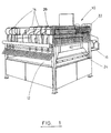
- the apparatus for forming stiffening panels having stiffening elements in the form of ribs comprises a substantially horizontal support means or bed onto which a planer panel may be received. Located above the bed are a plurality of forming assemblies which act to shape and fold the stiffening ribs. Each station is adapted to receive a rib blank, fold and shape the blank into the required configuration, generally being of a V-shaped section and secure it to the planer panel.
- the rib blank generally consists of a pre-creased strip of corrugated card or the like. Pre-creased blanks are made by a stamping/creasing process and machine (not shown).
- the creases formed therein generally comprise a central primary crease and two secondary creases placed one on either side of the primary crease.
- the forming assemblies comprise a support means for a rib blank, a first forming element or forming bar, roller means, an adhesive reservoir and a second forming element or former, together with means for actuating the abovementioned elements.
- the forming assemblies are supported on a framework, located above the bed, and are moveable in respect to one another on the framework. This enables the stations to be moved closer together or further apart depending on the specification of the panels required, namely the number and relative spacings of the ribs on any particular panel.
- Support means such as locating brackets, guide rails, runners or frame are provided to give initial support to a rib blank during the shaping and folding operation/process.
- the support means extend along the length of the bed and outwardly past and to one side of the apparatus.
- the guide acts as a feeder means by which the rib blank is presented in the required position for shaping and folding.
- rollers When the rib blank is placed on the supporting frame, one end of the blank abuts spaced rollers. When activated, the rollers exert a gripping action on the edge of the roller and cause it to be moved along the guide into a second position located above the bed.
- each forming assembly has a dedicated adhesive reservoir.
- the rollers advance the rib blank, they act to distribute the adhesive along the edges of the rib blank.
- a forming bar is also caused to advance, with the rib blank, towards the bed.
- the forming bar is located beneath the support for the rib blank.
- Each forming station is provided with a forming bar.
- the forming bar is generally an elongate metal fabrication. The particular shape and configuration of the forming bar is dependent on the shape required for the stiffening element. When a stiffening element of substantially V-shaped cross section is required, the cross sectional shape of the forming bar is of an inverted T.
- each forming assembly has a dedicated former.
- Each former comprises a substantially inverted V shaped elongate metal fabrication, the sides or arms of the inverted V have a hinged or spring loaded edge portion. The edges of the sides or arms of the fabrication are finished with a rounded or rolled edge which prevents the edge catching on and possibly tearing the material of the rib blank.
- Actuating means such as hydraulic or pneumatic rams are provided which act to move each former in a generally downwardly direction towards the rib blank.
- a planer panel to receive reinforcing ribs is fed into the apparatus and located on the bed.
- Pre-creased rib blanks are placed on the guide frame with the non creased side uppermost and are moved along the guide frame by the rollers so as to be located above the planer panel.
- a measured amount of adhesive is delivered to the edges of the blank.
- the forming bar also advances towards the bed, being located below the rib blank. Both are moved sufficiently over the bed so as to be located beneath the former.
- actuation means cause the former to move in a downwardly direction towards the rib blank.
- Continued movement of the former causes it to come into direct contact with the rib blank.
- This continued downward pressure causes the blank to be dislodged from the guide rail and brought into contact with the forming bar located beneath it.
- the area of contact between the rib blank and the upstanding portion of the forming bar is the region of the primary crease.
- the pressure applied by the former acting on the blank which is now in contact with the forming bar, said forming bar resisting this downward pressure. This causes the blank to fold along the central pre-formed crease, around the forming bar.
- one arm of the former passes either side of the forming bar.
- the hinged or spring loaded edges or arms of the former act to exert a gripping action on the blank as it is bent around the former. This gripping action is exerted in the region of the remaining pre-formed creases and serves to prevent the blank from flattening out as it is bent around the forming bar but rather to push or "pinch” together the regions of the blank which have been bent around the forming bar.
- the action of the spring loaded arms in preventing the blank from flattening out as it is folded along the crease serves to form the sides of the rib which is upstanding from the planer sheet and substantially triangular.
- the rolled or rounded edges of the spring loaded or hinged portions of the former assist the pinching action by moving cleanly over the surface of the rib blank and presenting no sharp edges which may "catch" on the rib blank and cause damage.
- the gripping or pinching action of the former also acts to assist the bonding of the formed rib to the planer panel.
- the continuing downward pressure of the former pushes the rib blank from the guide rails and towards the planer panel. This causes the substantially horizontal regions of the rib blank to contact the upper face of the planer panel.
- the adhesive which is carried on the edges of the rib blank cures and bonds the now shaped and formed rib to the planer panel.
- the former is moved away from the bed in an upwardly direction and the forming bar is retracted away from the bed.
- the planer panel, now bearing reinforcing ribs, is removed from the bed and the process repeated.
- a method of forming re-enforced stiffening panels for use with palletainers or like product containers wherein reinforcement of panels is provided by stiffening elements in the form of ribs comprising the steps of presenting a panel to a forming apparatus according to the invention, presenting a rib blank to said apparatus, the further step of causing at least two forming elements to cooperate to fold and shape said rib blank, the step of causing a hinged or spring loaded region of forming element to act on said rib blank during folding and the step of causing said folded and shaped rib blank to be secured to said panel.
- the apparatus 10 for forming stiffening panels having stiffening elements in the form of ribs comprises a bed 12 to receive a planer panel (11) onto which the ribs will be formed and secured thereto.
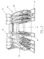
- a plurality of forming stations 14 Located above the bed 10 are a plurality of forming stations 14.
- Each forming station 14 includes a support means 16, a forming bar 16, roller means 20, an adhesive reservoir 22 and a former 24.
- the forming stations 14 are supported on a frame 26 and are moveable in relation to one another on the frame 26. Means are provided for actuation of the above-mentioned elements where required.
- the region of the support 16 which extends past the bed 12 acts as a means whereby the rib blank may be supported and fed into the apparatus 10 so as to located in the required position, under the former 24, prior to shaping and folding.
- Rollers 20 are provided to move the rib blank 28 along the support 16 into the required position.
- the rollers 20 also act to distribute a measured amount of hot melt adhesive, delivered from the reservoirs 22, along the edges of the rib blank 28.
- the forming bar 18 is located beneath the support 16 and thus also beneath the rib blank 28 when the latter is located on the support 16.
- the forming bar 18 is moveable in a generally horizontal direction and can advance with the rib blank 28, maintaining its position beneath it.
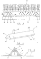
- the shape and configuration of the forming bar 18 is of an inverted T having a substantially horizontal lower portion 30 and an upstanding portion 32 located centrally of the lower portion 30.
- each forming station 12 has a dedicated former 24.
- Each former 24 comprises an elongate metal fabrication having a cross sectional shape of an inverted V.
- the lower portions of the arms 34 are provided with hinges 36 or are spring loaded.
- the edges 38 of the arms 34 are rounded.
- Supports 40 are provided to secure the former 28 to the frame 26 and actuating means are also provided to move the former 28 as required.
- a planer panel 11 which is to receive the reinforcing ribs, is fed into the apparatus 10 and placed on the bed 12.
- Pre-creased rib blanks 28 are placed on the portion of the support 16 which extends outwardly of the apparatus 10.
- Rollers 20 are actuated and move the rib blank 28 along the support towards the bed 10 whilst at the same time acting to coat the edges of the rib blank 28 with adhesive.
- the forming bar 18 is caused to move to follow the movement of the rib blank 28 maintaining a position beneath it. Movement of the rib blank 28 and the forming bar 18 continues until both are located above the planer panel positioned on the bed 10.
- the former 24 is activated to move downwards towards the rib blank 28.
- the former 24 causes it to contact the rib blank 28, and this downward pressure causes the rib blank 28 to be dislodged from the support 16 and brought into contact with the forming bar 18.
- the rib blank 28 contacts the top of the vertical portion 32 of the forming bar 18 in the region of the primary pre-formed crease.
- the vertical portion 32 of the forming bar 18 resists the downward movement of the rib blank 28 as it is pushed by the former 24. This causes the rib blank 28 to fold around the forming bar, along the line of the primary pre-formed crease.
- the sides or arms of the inverted V pass either side of the forming bar 18.
- the hinged portions 36 of the arms 34 act to exert a gripping or "pinching" action on the rib blank 28 as it is bent around the forming bar 18.
- the action of the hinged portions 36 is in the region of the secondary pre-formed creases causing the rib blank 28 to bend in this region.
- the action of the hinged portions 36 serves to prevent the rib blank 28 from flattening out as it is bent around the forming bar 18 and acts to push or "pinch” together the regions of the rib blank 28 which have been bent around the forming bar 28. This action assists to form the sides of the rib.
- the pushing or “pinching” action of the former 24 also acts to assist the bonding of the formed rib to the planer panel.
- This has the effect of causing the region 42 of the rib blank between the secondary creases and the longitudinal edge to retain a substantially horizontal attitude.
- the rib blank 28 is dislodged from the support 16, this causes the substantially horizontal regions 42 of the rib blank 28 to contact the upper face 44 of the planer panel.
- the adhesive carried on the edges of the rib blank contacts the planer panel and cures thus bonding the newly formed rib to the planer panel.
- the former 24 is moved away from the bed 10 in an upwardly direction and the forming bar 28, which is now located inside the reinforcing rib 46, is retracted from the bed, the stiffening panel now complete with reinforcing ribs located thereon, is removed and the process is repeated.
Landscapes
- Making Paper Articles (AREA)
- Crystals, And After-Treatments Of Crystals (AREA)
- Blow-Moulding Or Thermoforming Of Plastics Or The Like (AREA)
- Shaping Of Tube Ends By Bending Or Straightening (AREA)
- Bending Of Plates, Rods, And Pipes (AREA)
Claims (15)
- Gerät (10) zum Bilden von verstärkten Versteifungstafeln (44) zur Verwendung mit Palletainern oder ähnlichen Produkt-Containern, in dem die Verstärkung von Tafeln durch Versteifungselemente in der Form von Rippen (46) erfolgt, wobei das Gerät über ein erstes Stützmittel (12) verfügt, auf dem eine Tafel (11) zugeführt wird, ein zweites Stützmittel (16), auf dem ein Rippenrohling (28) zugeführt wird, mindestens eine Formungsbaugruppe (14) zum Abkanten und Formen des Rippenrohlings (28), Betätigungsmittel (nicht dargestellt) für die Formungsbaugruppe (14) und Mittel zum Befestigen einer abgekanteten und geformten Rippe (46) an der Tafel (11), wobei die Formungsbaugruppe (14) aus mindestens zwei Formungselementen (18), (24) besteht, die kooperieren, um einen Rippenrohling (28) abzukanten und zu formen, dadurch gekennzeichnet, dass das Formungselement (24) aus einer lang gestreckten Metalltafel-Anfertigung besteht, die die Querschnittsform eines umgekehrten V aufweist, worin der untere Abschnitt der Arme oder Seiten (34) der V-förmigen Anfertigung mit einem schwenkbaren oder federbelasteten Bereich (36) gebildet ist und der schwenkbare oder federbelastete Bereich (36) in einem Winkel in Bezug auf die Arme oder Seiten (34) gehalten wird.
- Gerät nach Anspruch 1, dadurch gekennzeichnet, dass der Bereich (38) der Arme oder Seiten (34) des Formungselements (24), der sich über die Lage des schwenkbaren oder federbelasteten Bereichs (36) hinaus erstreckt, eine Greif- oder Klemmwirkung auf den Rippenrohling (28) beim Abkanten und Formen ausübt.
- Gerät nach Anspruch 2, dadurch gekennzeichnet, dass die Ränder des Bereichs (38) der Seiten oder Arme (34) des umgekehrten V mit einem abgerundeten oder gewalzten Abschnitt (37) gefertigt sind.
- Gerät nach Anspruch 1, dadurch gekennzeichnet, dass die Formungselemente (18), (24) übereinander angeordnet/lokalisiert sind.
- Gerät nach Anspruch 1, dadurch gekennzeichnet, dass das Formungselement (18) aus einer geformten, lang gestreckten Metall-Anfertigung besteht.
- Gerät nach Anspruch 5, dadurch gekennzeichnet, dass die Querschnittsform des Formungselements (18) die eines umgekehrten T ist.
- Gerät nach Anspruch 1, dadurch gekennzeichnet, dass das erste Stützmittel (12) aus einem im Wesentlichen horizontalen Bett besteht, auf dem eine Tafel (14) zugeführt wird, bevor Rippen (46) zugeführt werden.
- Gerät nach Anspruch 1, dadurch gekennzeichnet, dass das zweite Stützmittel (16) aus Positionierungsstützen oder Führungsschienen besteht, um einen Rippenrohling (28) vor dem Abkanten und Formen zu empfangen.
- Gerät nach Anspruch 8, dadurch gekennzeichnet, dass Rollenmittel (20) vorgesehen sind, die verwendet werden, um zu bewirken, dass sich der Rippenrohling (28) entlang der Positionierungsstützen oder Führungsschienen (16) in die erforderliche Lage zum Abkanten und Formen bewegt.
- Gerät nach Anspruch 1, dadurch gekennzeichnet, dass Mittel zum Befestigen einer abgekanteten und geformten Rippe an einer Tafel (44) aus einem Kleber bestehen, der aus einem Behälter (22) vor dem Abkanten und Formen auf den Rippenrohling (28) gegeben wird.
- Verfahren zum Formen von verstärkten Versteifungstafeln zur Verwendung in Palletainern oder ähnlichen Produkt-Containern, in dem die Verstärkung von Tafeln durch Versteifungselemente in der Form von Rippen (46) erfolgt, bestehend aus den Schritten Zuführung einer Tafel (44) zu einem Formungsgerät (10), wie vorstehend in Anspruch 1 beschrieben, Zuführung eines Rippenrohlings (28) zu diesem Gerät, dem weiteren Schritt, dass mindestens zwei Formungselemente (18), (24) zur Kooperation veranlasst werden, um den Rippenrohling (28) abzukanten und zu formen, dem Schritt, dass bewirkt wird, dass ein schwenkbarer oder federbelasteter Bereich (36) des Formungselements (24) auf den Rippenrohling (28) beim Abkanten wirkt, und dem Schritt, dass bewirkt wird, dass der abgekantete und geformte Rippenrohling (28) an der Tafel (44) befestigt wird.
- Verfahren nach Anspruch 11, gekennzeichnet durch den Schritt, dass bewirkt wird, dass ein Rippenrohling (28) im Voraus gesickt oder anderweitig behandelt wird, um das Sicken entlang einer definierten Linie zu fördern.
- Verfahren nach Anspruch 12, gekennzeichnet durch den Schritt, dass eine derartige Abkantung mittels einer Formungsbaugruppe (14) bewirkt wird.
- Verfahren nach Anspruch 13, gekennzeichnet durch den Schritt, dass der Rippenrohling (28) entlang drei mit Zwischenraum angeordneten Faltlinien abgekantet wird.
- Verfahren nach Anspruch 14, gekennzeichnet durch den Schritt, dass bewirkt wird, dass eine Rippen-Formungsbaugruppe (14) die Rippe (46) in der gesickten Form fasst, um die Sickung beizubehalten, bis die Rippe (46) an der Tafel (44) befestigt wurde.
Applications Claiming Priority (3)
| Application Number | Priority Date | Filing Date | Title |
|---|---|---|---|
| GBGB9612129.8A GB9612129D0 (en) | 1996-05-28 | 1996-05-28 | Method and apparatus for forming stiffening elements |
| GB9612129 | 1996-05-28 | ||
| PCT/GB1997/001443 WO1997045253A1 (en) | 1996-05-28 | 1997-05-27 | Apparatus and method for forming stiffening means |
Publications (2)
| Publication Number | Publication Date |
|---|---|
| EP0907500A1 EP0907500A1 (de) | 1999-04-14 |
| EP0907500B1 true EP0907500B1 (de) | 2003-05-21 |
Family
ID=10795058
Family Applications (1)
| Application Number | Title | Priority Date | Filing Date |
|---|---|---|---|
| EP97924111A Expired - Lifetime EP0907500B1 (de) | 1996-05-28 | 1997-05-27 | Verfahren und vorrichtung zum formen von versteiften behälterwänden |
Country Status (7)
| Country | Link |
|---|---|
| US (1) | US6192571B1 (de) |
| EP (1) | EP0907500B1 (de) |
| AT (1) | ATE240832T1 (de) |
| AU (1) | AU2968297A (de) |
| DE (1) | DE69722201D1 (de) |
| GB (1) | GB9612129D0 (de) |
| WO (1) | WO1997045253A1 (de) |
Families Citing this family (2)
| Publication number | Priority date | Publication date | Assignee | Title |
|---|---|---|---|---|
| SE515044C2 (sv) * | 1999-10-15 | 2001-06-05 | Olv Pallen Ab | Lastpall, förfarande och anordning för framställning av lastpallen, ämne till lastpallen samt lastpallsaggregat av flera ämnen |
| KR100465848B1 (ko) * | 2003-05-07 | 2005-01-13 | 김병식 | 알루미늄 하니컴 복합 판넬의 연속적 제조 시스템 |
Family Cites Families (8)
| Publication number | Priority date | Publication date | Assignee | Title |
|---|---|---|---|---|
| US2481049A (en) * | 1947-04-16 | 1949-09-06 | Alfred J Stamm | Apparatus for corrugating sheet material |
| US3110340A (en) * | 1960-09-16 | 1963-11-12 | Metallic Engineering Co Inc | Panel fabricating machine |
| US3461711A (en) * | 1964-09-08 | 1969-08-19 | Frank R Ogilvie | Corrugating method and apparatus |
| US3828705A (en) * | 1972-12-21 | 1974-08-13 | Kasle Steel Corp | Method of manufacturing a pallet |
| US3892119A (en) * | 1974-03-04 | 1975-07-01 | Caterpillar Tractor Co | Forming apparatus for sheet material |
| DE2703694A1 (de) * | 1976-02-02 | 1977-08-04 | Francon | Verfahren und vorrichtungen zur herstellung von mit rippen versehenen metallprofilen und durch dieses verfahren hergestellte profile |
| US4596542A (en) | 1984-09-28 | 1986-06-24 | Moen Lenard E | Manufacture of internally reinforced boxes |
| GB9216977D0 (en) | 1992-08-11 | 1992-09-23 | Morrison Andrew R | Method and apparatus for use with produce containers |
-
1996
- 1996-05-28 GB GBGB9612129.8A patent/GB9612129D0/en active Pending
-
1997
- 1997-05-27 AT AT97924111T patent/ATE240832T1/de not_active IP Right Cessation
- 1997-05-27 DE DE69722201T patent/DE69722201D1/de not_active Expired - Lifetime
- 1997-05-27 US US09/194,381 patent/US6192571B1/en not_active Expired - Fee Related
- 1997-05-27 EP EP97924111A patent/EP0907500B1/de not_active Expired - Lifetime
- 1997-05-27 WO PCT/GB1997/001443 patent/WO1997045253A1/en not_active Ceased
- 1997-05-27 AU AU29682/97A patent/AU2968297A/en not_active Abandoned
Also Published As
| Publication number | Publication date |
|---|---|
| AU2968297A (en) | 1998-01-05 |
| GB9612129D0 (en) | 1996-08-14 |
| US6192571B1 (en) | 2001-02-27 |
| WO1997045253A1 (en) | 1997-12-04 |
| DE69722201D1 (de) | 2003-06-26 |
| EP0907500A1 (de) | 1999-04-14 |
| ATE240832T1 (de) | 2003-06-15 |
Similar Documents
| Publication | Publication Date | Title |
|---|---|---|
| JP7201787B2 (ja) | 箱の型板の折り曲げプロセスおよび機構 | |
| US5375493A (en) | Method and apparatus for feeding separator sheets to a stack | |
| US4197789A (en) | Tray in tray container forming | |
| US5336042A (en) | Palletizer with cap forming | |
| US4215522A (en) | Carton erecting apparatus | |
| US20050124478A1 (en) | Side wall flap folding mechanism for carton forming machine | |
| US4704100A (en) | Bag making apparatus and method | |
| AU662353B2 (en) | Improvements in or relating to packaging | |
| DE102008005407A1 (de) | Verfahren und Vorrichtung zum Herstellen von Packungen für Zigaretten | |
| CA1199512A (en) | Method and apparatus for erecting a carton with integral interior partitions | |
| EP4396090A1 (de) | Verpackungsvorrichtung, verpackungseinheit und verfahren zur herstellung von verpackungseinheiten | |
| EP0907500B1 (de) | Verfahren und vorrichtung zum formen von versteiften behälterwänden | |
| DE2730193A1 (de) | Geraet und verfahren zum aufsetzen eines deckels auf einen karton | |
| CN114945459A (zh) | 具有用于折叠预成型纸箱的站的包装机及其方法 | |
| US6449926B1 (en) | Process and apparatus for producing (cigarette) packs | |
| EP0660781B1 (de) | Vorrichtung und verfahren zum herstellen von akten | |
| PL171358B1 (en) | Method of and apparatus for mounting carrier casess on bottles | |
| EP2714523B1 (de) | Verfahren und vorrichtung zum herstellen einer palettenlosen verpackungseinheit | |
| EP4543768A1 (de) | Verfahren und verpackungsvorrichtung zur herstellung von verpackungseinheiten sowie applikationskopf zur jeweiligen verwendung hierbei | |
| EP0326390A2 (de) | Verfahren zum Herstellen von vierseitigen Blechbehältern | |
| DE102013204676A1 (de) | Verfahren und Vorrichtung zum Einschlagen eines Foliopapierrieses | |
| US3852936A (en) | Method of and a machine for forming and filling trays with articles | |
| EP0857657B1 (de) | Faltschachtel mit unterschiedlicher Bodenform und Verfahren zu seiner Herstellung | |
| CN220808740U (zh) | 一种纸箱支撑柱成型装置 | |
| AU2005211967B2 (en) | Machine and method for forming a plate by applying a mandrel |
Legal Events
| Date | Code | Title | Description |
|---|---|---|---|
| PUAI | Public reference made under article 153(3) epc to a published international application that has entered the european phase |
Free format text: ORIGINAL CODE: 0009012 |
|
| 17P | Request for examination filed |
Effective date: 19981222 |
|
| AK | Designated contracting states |
Kind code of ref document: A1 Designated state(s): AT BE CH DE DK ES FI FR GB GR IE IT LI LU MC NL PT SE |
|
| 17Q | First examination report despatched |
Effective date: 19990420 |
|
| RAP1 | Party data changed (applicant data changed or rights of an application transferred) |
Owner name: MORRISON, ANDREW ROBERT |
|
| RIN1 | Information on inventor provided before grant (corrected) |
Inventor name: MORRISON, ANDREW ROBERT |
|
| GRAG | Despatch of communication of intention to grant |
Free format text: ORIGINAL CODE: EPIDOS AGRA |
|
| RTI1 | Title (correction) |
Free format text: APPARATUS AND METHOD FOR FORMING REINFORCED STIFFENING PANELS FOR CONTAINERS |
|
| GRAG | Despatch of communication of intention to grant |
Free format text: ORIGINAL CODE: EPIDOS AGRA |
|
| GRAH | Despatch of communication of intention to grant a patent |
Free format text: ORIGINAL CODE: EPIDOS IGRA |
|
| GRAH | Despatch of communication of intention to grant a patent |
Free format text: ORIGINAL CODE: EPIDOS IGRA |
|
| GRAA | (expected) grant |
Free format text: ORIGINAL CODE: 0009210 |
|
| AK | Designated contracting states |
Designated state(s): AT BE CH DE DK ES FI FR GB GR IE IT LI LU MC NL PT SE |
|
| PG25 | Lapsed in a contracting state [announced via postgrant information from national office to epo] |
Ref country code: NL Free format text: LAPSE BECAUSE OF FAILURE TO SUBMIT A TRANSLATION OF THE DESCRIPTION OR TO PAY THE FEE WITHIN THE PRESCRIBED TIME-LIMIT Effective date: 20030521 Ref country code: LI Free format text: LAPSE BECAUSE OF FAILURE TO SUBMIT A TRANSLATION OF THE DESCRIPTION OR TO PAY THE FEE WITHIN THE PRESCRIBED TIME-LIMIT Effective date: 20030521 Ref country code: IT Free format text: LAPSE BECAUSE OF FAILURE TO SUBMIT A TRANSLATION OF THE DESCRIPTION OR TO PAY THE FEE WITHIN THE PRE;WARNING: LAPSES OF ITALIAN PATENTS WITH EFFECTIVE DATE BEFORE 2007 MAY HAVE OCCURRED AT ANY TIME BEFORE 2007. THE CORRECT EFFECTIVE DATE MAY BE DIFFERENT FROM THE ONE RECORDED.SCRIBED TIME-LIMIT Effective date: 20030521 Ref country code: FR Free format text: LAPSE BECAUSE OF NON-PAYMENT OF DUE FEES Effective date: 20030521 Ref country code: FI Free format text: LAPSE BECAUSE OF FAILURE TO SUBMIT A TRANSLATION OF THE DESCRIPTION OR TO PAY THE FEE WITHIN THE PRESCRIBED TIME-LIMIT Effective date: 20030521 Ref country code: CH Free format text: LAPSE BECAUSE OF FAILURE TO SUBMIT A TRANSLATION OF THE DESCRIPTION OR TO PAY THE FEE WITHIN THE PRESCRIBED TIME-LIMIT Effective date: 20030521 Ref country code: BE Free format text: LAPSE BECAUSE OF FAILURE TO SUBMIT A TRANSLATION OF THE DESCRIPTION OR TO PAY THE FEE WITHIN THE PRESCRIBED TIME-LIMIT Effective date: 20030521 Ref country code: AT Free format text: LAPSE BECAUSE OF FAILURE TO SUBMIT A TRANSLATION OF THE DESCRIPTION OR TO PAY THE FEE WITHIN THE PRESCRIBED TIME-LIMIT Effective date: 20030521 |
|
| REG | Reference to a national code |
Ref country code: GB Ref legal event code: FG4D |
|
| PG25 | Lapsed in a contracting state [announced via postgrant information from national office to epo] |
Ref country code: LU Free format text: LAPSE BECAUSE OF NON-PAYMENT OF DUE FEES Effective date: 20030527 Ref country code: IE Free format text: LAPSE BECAUSE OF NON-PAYMENT OF DUE FEES Effective date: 20030527 |
|
| REG | Reference to a national code |
Ref country code: CH Ref legal event code: EP |
|
| PG25 | Lapsed in a contracting state [announced via postgrant information from national office to epo] |
Ref country code: MC Free format text: LAPSE BECAUSE OF NON-PAYMENT OF DUE FEES Effective date: 20030531 |
|
| REG | Reference to a national code |
Ref country code: IE Ref legal event code: FG4D |
|
| REF | Corresponds to: |
Ref document number: 69722201 Country of ref document: DE Date of ref document: 20030626 Kind code of ref document: P |
|
| PG25 | Lapsed in a contracting state [announced via postgrant information from national office to epo] |
Ref country code: SE Free format text: LAPSE BECAUSE OF FAILURE TO SUBMIT A TRANSLATION OF THE DESCRIPTION OR TO PAY THE FEE WITHIN THE PRESCRIBED TIME-LIMIT Effective date: 20030821 Ref country code: PT Free format text: LAPSE BECAUSE OF FAILURE TO SUBMIT A TRANSLATION OF THE DESCRIPTION OR TO PAY THE FEE WITHIN THE PRESCRIBED TIME-LIMIT Effective date: 20030821 Ref country code: GR Free format text: LAPSE BECAUSE OF FAILURE TO SUBMIT A TRANSLATION OF THE DESCRIPTION OR TO PAY THE FEE WITHIN THE PRESCRIBED TIME-LIMIT Effective date: 20030821 Ref country code: DK Free format text: LAPSE BECAUSE OF FAILURE TO SUBMIT A TRANSLATION OF THE DESCRIPTION OR TO PAY THE FEE WITHIN THE PRESCRIBED TIME-LIMIT Effective date: 20030821 |
|
| PG25 | Lapsed in a contracting state [announced via postgrant information from national office to epo] |
Ref country code: DE Free format text: LAPSE BECAUSE OF FAILURE TO SUBMIT A TRANSLATION OF THE DESCRIPTION OR TO PAY THE FEE WITHIN THE PRESCRIBED TIME-LIMIT Effective date: 20030822 |
|
| PG25 | Lapsed in a contracting state [announced via postgrant information from national office to epo] |
Ref country code: ES Free format text: LAPSE BECAUSE OF FAILURE TO SUBMIT A TRANSLATION OF THE DESCRIPTION OR TO PAY THE FEE WITHIN THE PRESCRIBED TIME-LIMIT Effective date: 20030901 |
|
| NLV1 | Nl: lapsed or annulled due to failure to fulfill the requirements of art. 29p and 29m of the patents act | ||
| REG | Reference to a national code |
Ref country code: CH Ref legal event code: PL |
|
| REG | Reference to a national code |
Ref country code: IE Ref legal event code: MM4A |
|
| PLBE | No opposition filed within time limit |
Free format text: ORIGINAL CODE: 0009261 |
|
| STAA | Information on the status of an ep patent application or granted ep patent |
Free format text: STATUS: NO OPPOSITION FILED WITHIN TIME LIMIT |
|
| 26N | No opposition filed |
Effective date: 20040224 |
|
| EN | Fr: translation not filed | ||
| PGFP | Annual fee paid to national office [announced via postgrant information from national office to epo] |
Ref country code: GB Payment date: 20051129 Year of fee payment: 9 |
|
| PG25 | Lapsed in a contracting state [announced via postgrant information from national office to epo] |
Ref country code: GB Free format text: LAPSE BECAUSE OF NON-PAYMENT OF DUE FEES Effective date: 20060527 |
|
| GBPC | Gb: european patent ceased through non-payment of renewal fee |
Effective date: 20060527 |