EP0907300A2 - Puffersteueranlage in einem ATM Netzwerk zur Änderung von Zellenübertragungsgeschwindigkeit in Abhängigkeit von der Dauer von Stau - Google Patents
Puffersteueranlage in einem ATM Netzwerk zur Änderung von Zellenübertragungsgeschwindigkeit in Abhängigkeit von der Dauer von Stau Download PDFInfo
- Publication number
- EP0907300A2 EP0907300A2 EP19980118516 EP98118516A EP0907300A2 EP 0907300 A2 EP0907300 A2 EP 0907300A2 EP 19980118516 EP19980118516 EP 19980118516 EP 98118516 A EP98118516 A EP 98118516A EP 0907300 A2 EP0907300 A2 EP 0907300A2
- Authority
- EP
- European Patent Office
- Prior art keywords
- thresholds
- threshold
- set forth
- cell
- congestion status
- Prior art date
- Legal status (The legal status is an assumption and is not a legal conclusion. Google has not performed a legal analysis and makes no representation as to the accuracy of the status listed.)
- Granted
Links
Images


Classifications
-
- H—ELECTRICITY
- H04—ELECTRIC COMMUNICATION TECHNIQUE
- H04L—TRANSMISSION OF DIGITAL INFORMATION, e.g. TELEGRAPHIC COMMUNICATION
- H04L12/00—Data switching networks
- H04L12/54—Store-and-forward switching systems
- H04L12/56—Packet switching systems
- H04L12/5601—Transfer mode dependent, e.g. ATM
- H04L12/5602—Bandwidth control in ATM Networks, e.g. leaky bucket
-
- H—ELECTRICITY
- H04—ELECTRIC COMMUNICATION TECHNIQUE
- H04Q—SELECTING
- H04Q11/00—Selecting arrangements for multiplex systems
- H04Q11/04—Selecting arrangements for multiplex systems for time-division multiplexing
- H04Q11/0428—Integrated services digital network, i.e. systems for transmission of different types of digitised signals, e.g. speech, data, telecentral, television signals
- H04Q11/0478—Provisions for broadband connections
-
- H—ELECTRICITY
- H04—ELECTRIC COMMUNICATION TECHNIQUE
- H04L—TRANSMISSION OF DIGITAL INFORMATION, e.g. TELEGRAPHIC COMMUNICATION
- H04L12/00—Data switching networks
- H04L12/54—Store-and-forward switching systems
- H04L12/56—Packet switching systems
- H04L12/5601—Transfer mode dependent, e.g. ATM
- H04L2012/5629—Admission control
- H04L2012/5631—Resource management and allocation
- H04L2012/5632—Bandwidth allocation
- H04L2012/5635—Backpressure, e.g. for ABR
Definitions
- This invention relates to an asynchronous transfer mode network and, more particularly, to a buffer controller for an available bit rate service in the asynchronous transfer mode network and a method for controlling thereof.
- An available bit rate service is proposed for an asynchronous transfer mode in ATM (Asynchronous Transfer Mode) Forum Traffic Management Specification version 4.1, 1996.
- An allowable cell rate means the transmission cell rate at a terminal, and is dynamically changed depending upon the status of the network.
- the cell transmission rate is managed through a feedback control in the available bit rate service, and the feedback control reduces the cells to be disposed.
- the available bit rate service aims at provision of equal right to occupy each part of the network between users.
- terminal is applied to not only actual terminals for the users but also virtual transmission terminals and virtual receiving terminals such as a virtual source and a virtual destination defined in the ATM Forum Traffic Management Specification version 4.0.
- FIG. 1 illustrates the prior art asynchronous transfer mode network 1.
- a switching unit 2 is incorporated in the prior art asynchronous transfer mode network 1, and terminals 3/4 are connected to the asynchronous transfer mode network 1.
- the terminal 3 and the terminal 4 are assumed to be a data source and a data destination, respectively.
- the terminal 3 transmits data to the terminal 5
- the terminal 3 firstly transmits a forward resource management cell, which is abbreviated as "FRM" in figure 1
- the switching unit 2 transfers the forward resource management cell FRM to the terminal 4.
- the terminal 4 receives the forward resource management cell FRM, the terminal 4 returns a backward resource management cell, which is abbreviated as "BRM" in figure 1, through the switching unit 2 to the terminal 3.
- FRM forward resource management cell
- the switching unit 2 has pieces of status data information representative of the congestion of the network 1, and writes control bits ER, a congestion indication bit CI and a no increase bit NI in the forward resource management cell FRM or the backward resource management cell BRM.
- the control bits ER are representative of an explicit rate, and the explicit rate is determined on the basis of the current status of the network 1.
- the congestion indication bit CI indicates whether the network is in congestion status or not, and the no increase bit NI indicates whether the terminal 3/4 is allowed to increase the transmission rate or not.
- the congestion indication bit CI is changed between "1" indicative of congestion status and "0" indicative of non-congestion status.
- the no increase bit NI is also changed between "1" indicative of prohibition from increase of transmission rate and "0" indicative of permission to increase the transmission rate.
- the terminal 3 maintains or changes the transmission rate of data cells on the basis of the control bits, the congestion indication bit and the no increase bit NI written in the backward resource management cell BRM, and transmits data cells through the switching unit 2 to the terminal 4 at the data transmission rate.
- the terminals 3/4 carry out the data transmission under the control of the switching unit.
- a virtual source and a virtual destination are defined for the available bit rate service.
- the virtual source and the virtual destination are located in the asynchronous transfer mode network, and virtually behave as the terminals.
- the virtual source and the virtual destination virtually process the forward resource management cell FRM and the backward resource management cell BRM, and divide the transmission control loop for the forward/backward resource management cells into segments.
- the division into the segments is desirable, because the segments accelerate the transmission of the control data information.
- the acceleration of the transmission results in improvement of the rate controlling characteristics in the terminal 3.
- FIG. 2 illustrates another prior art asynchronous transfer mode network 10 for the available bit rate service, and the prior art asynchronous transfer mode network 10 provides a data transmission control loop between terminals 11/12.
- a combination of the virtual source VS and the virtual destination VD is referred to as "virtual terminal module", and a position closer to a transmission terminal and another position closer to a receiving terminal are called as “upstream side” and "downstream side”, respectively.
- Two virtual terminal modules 13/14 are inserted into the transmission control loop, and divide the data transmission control loop into segments 15a/ 15b/ 15c.
- the terminal 11 communicates with the virtual terminal module 14, and a forward resource management cell FRM1 and a backward resource management cell BRM1 are used for the transmission control therebetween.
- the virtual terminal modules 13 and 14 communicates with each other by using a forward resource management cell FRM2 and a backward resource management cell BRM2.
- the virtual terminal module 14 communicates with the terminal 12, and a forward resource management cell FRM3 and a backward resource management cell BRM3 are used for the transmission control therebetween.
- the data transmission is carried out from the terminal 11 through the virtual terminal modules 13/ 14 to the terminal 12, and the data transmission rate is varied between the segments 15a/ 15b/ 15c.
- a burst traffic from plural terminals variation of area available for the data transmission and variation of transmission rate due to congestion at a terminal cause the switching unit 2 and the virtual terminal module 13/ 14 to pile up a large amount of data cells to be transferred, and cell buffers are provided in the switching unit 2 and the virtual terminal module 13/ 14 so as to temporarily store the data cells.
- the switching unit and the virtual terminal module enters into congestion status. Therefore, the prior art asynchronous transfer mode networks 1/ 10 requires a buffer controller for prohibiting the cell buffer from the congestion status.
- Japanese Patent Publication of Unexamined Application No. 8-223174 teaches a controller for the cell buffers.
- the congestion detector monitors the buffer memory to see how many asynchronous transfer mode cells enter into a queue.
- the controller determines the asynchronous transfer mode network to enter into congestion status, and notifies plural paths selected from a connection table.
- the criterion is the queue length or the number of asynchronous transfer mode cells stored in the buffer memory.
- Another method for controlling congestion status is disclosed in Japanese Patent Publication of Unexamined Application No. 7-183886.
- two pairs of thresholds i.e., four thresholds are given to the buffer in each node, and the buffer is monitored to see whether or not the queue reaches any one of the thresholds.
- the first pair of thresholds offers a boundary for a notification of the congestion status to a receiving terminal and a boundary for the recovery therefrom
- the second pair of thresholds offers a boundary for an interruption of cell transfer from a transmitting terminal and a boundary for a recovery therefrom.
- the queue length or the number of asynchronous transfer mode cells is the criteria of the congestion status.
- Still another congestion controlling method is disclosed in Japanese Patent Publication of Unexamined Application No. 6-30019.
- the load manager monitors the common buffer memory to see whether the maximum number of asynchronous transfer mode cells exceeds a predetermined threshold or not. When the maximum number exceeds the threshold, the load manager recognizes the congestion status.
- the criterion for the congestion status is the queue length or the number of asynchronous transfer mode cells stored in the common buffer memory.
- the queue length is compared with a threshold in the prior art controlling methods so as to determine whether in the congestion status or not.
- a problem is encountered in the prior art controlling methods in the transmission cell rate too small to quickly recover the channel from the congestion status.
- the transmission cell rate is reduced to a predetermined value. If the queue length is close to the threshold after entry into the congestion status, the predetermined transmission cell rate is too small to quickly recover the channel from the congestion status.
- the prior art controller notifies the congestion status to the transmission terminal so as to reduce the transmission cell rate.
- the transmission terminal restarts the transmission of asynchronous transfer mode cells at the reduced transmission cell rate.
- the buffer is assumed to increase and decrease the queue slightly shorter than the threshold for long time.
- the prior art controller does not notify the congestion status to the transmission terminal, and keeps the transmission cell rate constant. In this situation, if the burst traffic takes place, the buffer can not store all the asynchronous transfer mode cells, and part of the asynchronous transfer mode cells overflows the buffer. Thus, the prior art controllers can not achieve a low cell loss ratio in spite of the available bit rate service.
- the present invention proposes to change a transmission cell rate depending upon a lapse of time from entry into congestion status.
- a buffer controller operative to transfer data cells from a transmitting terminal to a receiving terminal both incorporated in an asynchronous transfer mode network for an available bit rate service
- a cell buffer for temporarily storing at least one queue of the cells
- a judging means for determining a current degree of congestion status in the cell buffer on the basis of a lapse of time after entry into the congestion status and said length of the at least queue
- a calculating means for calculating transmission cell rates different from one another through different algorithms
- a selecting means responsive to a control signal representative of the current degree of congestion status so as to cause the calculating means to supply one of the transmission cell rates to the transmission terminal.
- a method of controlling a cell transmission from a transmitting terminal to a receiving terminal both incorporated in an asynchronous transfer mode network for an available bit rate service comprising the steps of checking a queue of cells to see whether or not a queue length is indicative of congestion status, counting a lapse of time after entry into the congestion status, determining a current degree of the congestion status on the basis of the queue length and the lapse of time, changing a transmission cell rate to a value appropriate to the current degree of congestion status, and notifying the value of the transmission cell rate to the transmitting terminal so as to vary the amount of the cells supplied from the transmitting terminal per unit time.
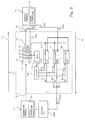
- a buffer controller 21 embodying the present invention is connected between a transmitting terminal 22 and a receiving terminal 23.
- Switching units SW10 and SW11 are inserted between the buffer controller 21 and the transmitting/receiving terminals 22/ 23 in the available bit rate service.
- Arrow AR1 is indicative of a direction from the transmitting terminal 22 toward the receiving terminal 23, and is referred to as "forward direction”.
- arrow AR2 is indicative of the opposite direction to the forward direction, and is referred to as "backward direction”.
- the buffer controller 21 includes an input port 21a connected to the transmitting terminal 22, an output port 21b connected to the receiving terminal 23 and a cell buffer 21c connected between the input port 21a and the output port 21b.
- the cell buffer 21c has an input port 21d connected to the input port 21a and an output port 21e connected to the output port 21b.
- Asynchronous transfer mode cells are supplies from the transmitting terminal 22 to the cell buffer 21c, and are accumulated in the cell buffer 21c from a storage region closest to the output port 21b toward a storage region farthest from the output port 21b.
- the first asynchronous transfer mode cell is stored in the storage region closest to the output port 21b, and the last asynchronous transfer mode cell is stored in a storage region closer to the input port 21d than the storage regions occupied by the asynchronous transfer mode cells.
- the first asynchronous transfer mode cell is firstly output from the storage region to the output port 21e.
- the cell buffer 21c has a first-in first-out buffer, and the cells form queues for virtual connections in the first-in first-out buffer.
- the queue varies the length from the memory region closest to the output port 21e, and the cell buffer 21c produces a control data signal CTL1 representative of the queue length for each virtual connection and, accordingly, the piece of internal congestion status.
- the buffer controller 21 further includes an output rate controlling unit 21f provided for the output port 21e, a timer 21g connected to the cell buffer 21c, plural calculating units 21h/ 21j/ 21k connected to the cell buffer 21c and an external information source such as a buffer controllers 23a and a selector 21m connected to the timer 21g and the calculating units 21h to 21k.
- an output rate controlling unit 21f provided for the output port 21e
- a timer 21g connected to the cell buffer 21c
- plural calculating units 21h/ 21j/ 21k connected to the cell buffer 21c
- an external information source such as a buffer controllers 23a and a selector 21m connected to the timer 21g and the calculating units 21h to 21k.
- the output rate controlling unit 21f takes the piece of internal congestion status information represented by the control data signal CTL1 and pieces of network congestion status information represented by another control data signal CTL2 into account so as to vary a transmission cell rate.
- the control data signal CTL2 is supplied to the output rate controlling unit 21f in the form of the backward resource management cell.
- the backward resource management cell is supplied from the receiving terminal 23, it contains the pieces of network congestion status information reported from the switching unit SW11 and other switching units (not shown).
- the timer 21c stores plural thresholds Q1, Q2 ... and Qn for the queue length and a threshold Tth for excess times.
- the plural thresholds Q1 to Qn are representative of degrees of the congestion status.
- the threshold Q2 is greater than the threshold Q1 and less than the threshold Qn, and the thresholds Q1 to Qn relates to the calculating units 21h, 21j ... and 21k, respectively.
- the timer 21g compares the queue length for each virtual connection with the thresholds Q1/ Q2/ Qn to see whether the queue length exceeds the thresholds Q1/ Q2/ Qn or not. When the queue length exceeds the thresholds Q1/ Q2/ Qn, the timer 21g starts to count excess times at the thresholds Q1/ Q2/ Qn.
- the excess times from the thresholds Q1/ Q2/ Qn are expressed by T1, T2 and Tn, respectively.
- the threshold Tth is common to the excess times T1/ T2/ Tn.
- the timer 21c compares the excess times T1/ T2/ Tn with the threshold Tth to see whether the excess times T1/ T2/ Tn go over the threshold Tth or not.
- the timer 21g produces a control signal CTL4 representative of the excess over the threshold Tth, and supplies the control signal CTL4 to the selector 21m. While the queue is being shortened, the timer 21g produces the control signal CTL4 at each of the thresholds Q1 to Qn. Therefore, the control signal CTL4 further represents decrease to each threshold Q1 - Qn.
- the calculating units 21h/ 21j/ 21k have respective algorithms for calculating the transmission cell rate, and the algorithms are different from one another.
- the control signal CTL1 is supplied to the calculating units 21h/ 21j/ 21k, and a control data signal CTL5 is further supplied from the buffer controller 23a to the calculating units 21h/ 21j/ 21k.
- the control data signal CTL5 is representative of pieces of data information used for calculation of the transmission cell rate.
- the calculating units 21h/ 21j/ 21k calculate the transmission cell rate through the algorithms, and produces control data signals ER1, ER2, ... and ERn representative of the values of the transmission cell rate or the explicit rate, respectively.
- the calculating units 21h to 21k calculate the transmission cell rate on the basis of the same queue length and the same pieces of data information, the value of the transmission cell rate is decreased in the order from the control data signal ER1 toward the control data signal ERn.
- the calculating units 21h and 21j are respectively referred to as “first calculating unit” and “second calculating unit”, and the calculating unit 21k is referred to as "n-th calculating unit”.
- the selector 21m is responsive to the control data signal CTL4 so as to determine what calculating unit 21h to 21k is the most adequate to calculate the transmission cell rate.
- the selector 21m produces selecting signals CS1, CS2, ... and CSn representative of change from one calculating unit to another, and supplies the selecting signals CS1 to CSn to the calculating units 21h to 21k, respectively.
- the control data signal ER1/ ER2/ ERn from the selected calculating unit is supplied to the buffer controller 22a of the transmitting terminal 22 as a control data signal ERnew representative of an explicit rate.
- the k-th calculating unit is located between the calculating unit 21j and the calculating unit 21k, and a selecting signal CSk is supplied from the selector 21m to the k-th calculating unit.
- a threshold Qk is corresponding to the k-th calculating unit, and an excess time Tk represents the lapse of time from the threshold Qk.
- the transmitting terminal 22 is successively supplying asynchronous transfer mode cells to the cell buffer 21c, and the asynchronous transfer mode cells are accumulated therein.
- the asynchronous transfer mode cells enters into the queue, and increase the queue length Q.
- the cell buffer 21c notifies the queue length Q to the timer 21g through the control data signal CTL1.
- the timer starts the count, and increments the excess time Tk.
- the timer supplies the control signal CTL4 representative of the excess over the threshold Tth to the selector 21m, and the selector changes the selecting signal CSk to inactive level and the selecting signal CSk+1 to active level.
- the selecting signal CSk+1 makes the (k+1)-th calculating unit supply the control data signal ERnew to the buffer controller 22a.
- the transmission cell rate is reduced, and the queue length Q in the cell buffer 21c becomes shorter.
- the timer supplies the control signal CTL representative of the decrease to the threshold Qk, and the selector 21m changes the selecting signal CSk+1 to the inactive level and the selecting signal CSk to the active level.
- the control data signal ERnew is supplied from the k-th calculating unit instead of the (k+1)-th calculating unit.
- the asynchronous transfer mode cells still make the queue longer.
- the timer 21g starts to count the excess time Tk+1, again, and increment the excess time Tk+1.
- the timer 21g supplies the control signal CTL4 representative of the excess over the threshold Qk+1 to the selector 21m.
- the selector 21m changes the selecting signal CSk+1 to the inactive level and the selecting signal CSk+2 to the active level.
- the (k+2)-th calculating unit supplies the control data signal ERnew to the buffer controller 22a.
- the buffer controller 21 sequentially changes the calculating unit as indicated by arrows shown in figure 4, and the transmission cell rate is varied depending upon the lapse of time after the entry into the congestion status.
- the congestion status is light, the transmission rate is slightly reduced, and the asynchronous transfer mode network keeps the throughput relatively high.
- the congestion status is serious, the transmission rate is stepwise decreased, and the cell buffer 21c is prevented from the overflow.
- the calculating units 21h to 21k employ different algorithms for calculating the transmission cell rates, and the algorithms are adopted to force the queue length to the associated thresholds Q1 to Qn. This results in the control data signal ERnew effective against the congestion status in the available bit rate service.
- the asynchronous transfer mode cells are managed for each of the virtual connections. Even if a queue for a virtual connection enters into the congestion status, the transmission cell rate is stepwise increased together with the lapse of time, and the queue is quickly recovered from the congestion status. For this reason, the cell buffer 21c is quickly released form the virtual connection, and the cell buffer 21c is evenly shared between the virtual connections.
- the selector 21m selectively activates the calculating units 21h to 21k. This means that non-selected calculating units do not calculate the transmission rate. Thus, only one calculating unit is working for the transmission cell rate, and the electric power is saved.
- FIG. 5 illustrates another buffer controller 31 embodying the present invention.
- the components of the buffer controller 31 is similar to those of the buffer controller 21 except a selector 31a. For this reason, the other components are labeled with the same references designating corresponding components of the buffer controller 21 without detailed description.
- the calculating units 21h to 21k calculate the transmission cell rates at all times so as to vary the control data signals ER1 to ERn, and supply the control data signals ER1 to ERn to the selector 31a. For this reason, the selector 31a only selects one of the control data signals ER1 to ERn in response to the control signal CTL4. Although the electric power consumption is larger than that of the buffer controller 21, the buffer controller 31 changes the control data signal ERnew faster than the buffer controller 21.
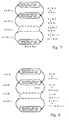
- the buffer controller 31 changes the transmission cell rate as similar to the buffer controller 21 through the sequence shown in figure 4. Another control sequence shown in figure 6 is available for each of the buffer controllers 21/ 31.
- the timer 21g starts to count the excess time Tk at the threshold Qk
- the selector 21m/ 31a changes the calculating unit from the k-th calculating unit to the (k+1)-th calculating unit as similar to the control sequence shown in figure 4.
- the reduction of the transmission cell rate is different from that of the control sequence shown in figure 4.
- the queue length Q is shortened, and reaches the threshold Qk.
- the timer 21g does not immediately supply the control signal CTL4 representative of the arrival at the threshold Qk to the selector 21m/ 31a, but starts to count the excess time Tk_u. If the queue length Q does not exceed the threshold Qk again until the threshold Tth, the selector 21m/ 31a changes the calculating unit from (k+1)-th to k-th.
- the control sequence shown in figure 6 is hardly affected by momentary increase of asynchronous transfer mode cells, and makes the transmission of the asynchronous transfer mode cells stable rather than the control sequence shown in figure 4.
- the timer 21g has a first set of thresholds Q1_o to Qn-1_o and a second set of thresholds Qn-1_u to Q1_u.
- the thresholds Q1_o to Qn-1_o are greater than the corresponding thresholds Qn-1_u to Q1_u.
- the timer 21g uses the first set of thresholds Q1_o to Qn-1_o during the increase of the queue length Q and the second set of thresholds Qn-1_u to Q1_u during the decrease of the queue length Q.
- the two sets of thresholds Q1_o to Qn-1_o and Qn-1_u to Q1_u offers a hysteresis to the control sequence.
- the buffer controller 21/ 31 controls the transmitting terminal 22 through the control sequence shown in figure 7, the asynchronous transfer mode cells make the queue long, and the queue length Q exceeds the threshold Qk_o. Then, the timer 21g starts to count the excess time Tk, and increments the excess time Tk. When the excess time Tk reaches the threshold Tth, the timer 21g supplies the control signal CTL4 to the selector 21m/ 31a, and the selector 21m/ 31a changes the k-th calculating unit to the (k+1)-th calculating unit so as to reduce the transmission cell rate.
- the queue length Q reaches the threshold Qk_u smaller in value than the threshold Qk_o, and the selector 21m/ 31a changes the (k+1)th calculating unit to the k-th calculating unit.
- Still another control sequence is available for the buffer controller 21/ 31, and is illustrated in figure 8.
- the control sequence shown in figure 8 uses variable threshold for lapse of time. While the asynchronous transfer mode cells are making the queue longer, the queue length Q exceeds the threshold Qk at a certain time. Then, the timer 21g starts to count the excess time Tk, and increments the excess time Tk. When the excess time Tk reaches the threshold Tth_k the timer 21g supplies the control signal CTL4 to the selector 21m/ 31a, and the selector 21m/ 31a changes the k-th calculating unit to the (k+1)-th calculating unit so as to reduce the transmission cell rate.
- the selector 21m/ 31a changes the (k+1)th calculating unit to the k-th calculating unit.
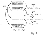
- Figure 9 illustrates another control sequence available for the buffer controllers 21/ 31.
- the calculating unit 21h to 21k are sequentially changed depending upon the lapse of time after the excess over the threshold Qth.
- the timer 21g has only one threshold Qth for the queue length Q.
- the queue length Q exceeds the threshold Qth at a certain timing. Then, the timer 21g starts to count the excess time T, and increments the excess time T. When the excess time T reaches the threshold Tth'_k, the timer 21g supplies the control signal CTL4 to the selector 21m/ 31a, and the selector 21m/ 31a changes the k-th calculating unit to the (k+1)-th calculating unit so as to reduce the transmission cell rate.
- the selector 21m/ 31a changes the (k+1)th calculating unit to the first calculating unit.
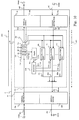
- FIG 10 illustrates a virtual terminal system 41 embodying the present invention.
- the virtual terminal system 41 largely comprises a buffer controller 42 and virtual terminal modules 43/ 44.
- the buffer controller 42 is similar in arrangement to the buffer controller 21, and components thereof are labeled with the same references designating corresponding components of the buffer controller 21.
- Asynchronous transfer mode cells form queues in the cell buffer 21c for respective virtual connections.
- figure 10 only shows the function blocks for a data transmission from a transmitting terminal to a receiving terminal, the virtual terminal system 41 symmetrically behaves between the data transmission terminal and the data receiving terminal, and has another set of function blocks for a data transmission from the receiving terminal to the transmission terminal.
- the virtual terminal module 43 includes a virtual destination 43a and a virtual source 43b.
- the virtual destination 43a has an input port 43c, and receives forward resource management cells from the transmitting terminal.
- the virtual destination 43a transfers a data cell of each forward resource management cell FRM1 to the input port 21a.
- the virtual source 43b has an output port 43d, and transfers the control data signal BRM1 representative of a backward resource management cell to the transmitting terminal.
- the virtual terminal module 44 includes a virtual destination 44a and a virtual source 44b.
- the virtual destination 44a has an input port 44c, and receives a backward resource management cell BRM2.
- the virtual destination 44a transfers a control data signal ER representative of an explicit rate to the calculating units 21h to 21k and the output rate controlling unit 21f.
- the virtual source 44b has an output port 44d, and transfers forward resource management cells FRM2 to a receiving terminal.
- the virtual destinations 43a/ 44a and the virtual sources 43b/ 44b are adopted to realize a destination behavior and a source behavior.
- the virtual destinations 43a/ 44a are respectively paired with the virtual sources 43b/ 44b, and the virtual terminal modules 43/ 44 virtually realize a terminal behavior during the available bit rate service.
- the terminal behavior is described in ATM Forum Traffic Management Specification Version 4.0.
- the virtual terminal system 41 behaves as follows.
- the transmitting terminal supplies a forward resource management cell FRM1 to the virtual destination 43a
- the virtual destination 43a separates a data cell from the forward resource management cell FRM1, and transfers the data cell to the cell buffer 21c.
- the data cell enters into a queue formed in the cell buffer 21c.
- the virtual destination 44a receives a backward resource management cell BRM2, and extracts the explicit rate from the backward resource management cell BRM2.
- the virtual destination 44a produces the control data signal ER representative of the explicit rate, and supplies the control data signal ER to the calculating units 21h to 21k and the output rate controlling unit 21f.
- the output rate controlling unit 21f determines an allowable cell rate on the basis of the explicit rate, and reads out the data cells from the cell buffer 21c at the allowable cell rate.
- Selected one of the calculating units 21h to 21k calculates an explicit rate ERnew referred to as "transmission cell rate" in the description on the first embodiment on the basis of the allowable bit rate supplied from the output rate controlling unit 21f and the explicit rate ER supplied from the virtual destination 44a, and supplies the control data signal ERnew representative of the explicit rate to the virtual source 43b.
- the virtual terminal module 43 i.e., the combination of the virtual destination 43a and the virtual source 43b receives the forward resource management cell FRM1 from the transmitting terminal, and stores the explicit rate represented by the control data signal ERnew in the backward resource management cell BRM1 so as to return the backward resource management cell BRM1 to the transmitting terminal.
- the cell buffer 21c in the virtual terminal system 41 is controlled as similar to that of the first embodiment, and the virtual terminal system 41 achieves all the advantages of the first embodiment.
- Figure 11 illustrates an asynchronous transfer mode switching unit 51 embodying the present invention for the available bit rate service.
- the buffer controller 21 is applied to the asynchronous transfer mode switching unit 51.
- the asynchronous transfer mode switching unit 51 largely comprises the buffer controller 21, input processing module 52a/ 52b and output processing modules 53a/ 53b.
- figure 11 only shows the function blocks for a data transmission from a transmitting terminal to a receiving terminal, the asynchronous transfer mode switching unit 51 symmetrically behaves between the data transmission terminal and the data receiving terminal, and has another set of function blocks for a data transmission from the receiving terminal to the transmission terminal.
- Components of the buffer controller 21 incorporated in the switching unit 51 are similar to those of the first embodiment, and are labeled with the same references designating corresponding components of the buffer controller 21 implementing the first embodiment.
- Virtual queues are formed in the cell buffer 21c for respective virtual connections.
- the input processing module 52a is connected between an input port 54a and the input port 21a, and the other input processing module 54b is connected between an input port 54b and the calculating units 21h to 21k.
- the output processing module 53a is connected between the calculating units 21h to 21k and an output port 55a, and the other output processing module 53b is connected between the output port 21b and an output port 55b.
- the input port 54a and the output port 55a are connected to a transmission terminal (not shown), and the other input port 54b and the other output port 55b are connected to a receiving terminal (not shown).
- the input processing modules 52a/ 52b receive forward resource management cells FRM11 and backward resource management cells BRM11 from the input ports 54a/ 54b, and carry out an analysis of header and a discrimination of destination.
- the output processing modules 53a/ 53b carry out a read-out control for the cell stored in the cell buffer 21c and a change of contents in the fields of the forward/backward resource management cells assigned to the explicit rate, the congestion indication and the no increase.
- the asynchronous transfer mode switching unit 51 for the available bit rate service makes the input processing module 52a analyze the header of the forward resource management cell FRM11 so as to store the forward resource management cell FRM11 in the cell buffer 21c.
- the output rate controlling unit 21f instructs the cell buffer 21c to successively transfer the forward resource management cells to the output processing module 53b.
- the input processing module 52a extracts the available cell rate and explicit rate from the forward resource management cell FRM11.
- the input processing module 52a supplies pieces of control data information representative of the available cell rate and the explicit rate to the calculating units 21h to 21k.
- the input processing module 52b receives the backward resource management cell BRM11, and extracts the explicit rate from the backward resource management cell BRM11.
- the input processing module 52b produces a control data signal ER, and supplies it to the output rate controlling unit 21f and the calculating units 21h to 21k.
- Selected one of the calculating units 21h to 21k calculates the explicit rate ERnew, and sends the explicit rate ERnew to the output processing unit 53a.
- the output processing unit 53a stores the explicit rate ERnew in a field of the backward resource management cell BRM11, and supplies the backward resource management cell BRM11 to the transmitting terminal.
- the cell buffer 21c is controlled as similar to that of the first embodiment, and all the advantages are achieved by the fourth embodiment.
- the buffer controller 21/ 31 checks the lapse of time after entry into the congestion status so as to determine the degree of congestion status, and changes the transmission cell rate depending upon the degree of congestion status. As a result, the buffer controller 21/31 achieves a high throughput without sacrifice of cell loss ratio.
- the buffer controller 21/31 calculates the explicit rate, and supplies it to the transmitting terminal. For this reason, the buffer controller 21/ 31 effectively controls the transmission cell rate in the available bit rate service.
- the buffer controller 21/ 31 quickly evacuates the asynchronous transfer mode cells from each queue, and any virtual connection does not continuously occupy the cell buffer 21c.
- the timer 21g serves as a judging means, and the calculating units 21h to 21k as a whole constitute a calculating means.
- the selector 21m/ 31a serves as the selecting means.
Applications Claiming Priority (3)
| Application Number | Priority Date | Filing Date | Title |
|---|---|---|---|
| JP269049/97 | 1997-10-01 | ||
| JP9269049A JP2959539B2 (ja) | 1997-10-01 | 1997-10-01 | バッファ制御方法および装置 |
| JP26904997 | 1997-10-01 |
Publications (3)
| Publication Number | Publication Date |
|---|---|
| EP0907300A2 true EP0907300A2 (de) | 1999-04-07 |
| EP0907300A3 EP0907300A3 (de) | 2000-04-12 |
| EP0907300B1 EP0907300B1 (de) | 2006-02-15 |
Family
ID=17466971
Family Applications (1)
| Application Number | Title | Priority Date | Filing Date |
|---|---|---|---|
| EP19980118516 Expired - Lifetime EP0907300B1 (de) | 1997-10-01 | 1998-09-30 | Puffersteueranlage in einem ATM Netzwerk zur Änderung von Zellenübertragungsgeschwindigkeit in Abhängigkeit von der Dauer von Stau |
Country Status (4)
| Country | Link |
|---|---|
| US (1) | US6438138B1 (de) |
| EP (1) | EP0907300B1 (de) |
| JP (1) | JP2959539B2 (de) |
| DE (1) | DE69833472T2 (de) |
Cited By (41)
| Publication number | Priority date | Publication date | Assignee | Title |
|---|---|---|---|---|
| GB2349296A (en) * | 1999-04-21 | 2000-10-25 | 3Com Corp | Reduction of imbalance in transmsit queues in a network switch |
| WO2001002965A2 (en) * | 1999-06-30 | 2001-01-11 | Broadcom Corporation | Memory management unit for a network switch |
| US6430188B1 (en) | 1998-07-08 | 2002-08-06 | Broadcom Corporation | Unified table for L2, L3, L4, switching and filtering |
| US6535510B2 (en) | 2000-06-19 | 2003-03-18 | Broadcom Corporation | Switch fabric with path redundancy |
| US6678678B2 (en) | 2000-03-09 | 2004-01-13 | Braodcom Corporation | Method and apparatus for high speed table search |
| US6781898B2 (en) | 2002-10-30 | 2004-08-24 | Broadcom Corporation | Self-repairing built-in self test for linked list memories |
| US6826561B2 (en) | 2000-05-22 | 2004-11-30 | Broadcom Corporation | Method and apparatus for performing a binary search on an expanded tree |
| US6839349B2 (en) | 1999-12-07 | 2005-01-04 | Broadcom Corporation | Mirroring in a stacked network switch configuration |
| US6850542B2 (en) | 2000-11-14 | 2005-02-01 | Broadcom Corporation | Linked network switch configuration |
| US6851000B2 (en) | 2000-10-03 | 2005-02-01 | Broadcom Corporation | Switch having flow control management |
| US6859454B1 (en) | 1999-06-30 | 2005-02-22 | Broadcom Corporation | Network switch with high-speed serializing/deserializing hazard-free double data rate switching |
| US6988177B2 (en) | 2000-10-03 | 2006-01-17 | Broadcom Corporation | Switch memory management using a linked list structure |
| US6999455B2 (en) | 2000-07-25 | 2006-02-14 | Broadcom Corporation | Hardware assist for address learning |
| US7009968B2 (en) | 2000-06-09 | 2006-03-07 | Broadcom Corporation | Gigabit switch supporting improved layer 3 switching |
| US7009973B2 (en) | 2000-02-28 | 2006-03-07 | Broadcom Corporation | Switch using a segmented ring |
| US7020166B2 (en) | 2000-10-03 | 2006-03-28 | Broadcom Corporation | Switch transferring data using data encapsulation and decapsulation |
| US7031302B1 (en) | 1999-05-21 | 2006-04-18 | Broadcom Corporation | High-speed stats gathering in a network switch |
| US7035286B2 (en) | 2000-11-14 | 2006-04-25 | Broadcom Corporation | Linked network switch configuration |
| US7035255B2 (en) | 2000-11-14 | 2006-04-25 | Broadcom Corporation | Linked network switch configuration |
| US7042843B2 (en) | 2001-03-02 | 2006-05-09 | Broadcom Corporation | Algorithm for time based queuing in network traffic engineering |
| US7082133B1 (en) | 1999-09-03 | 2006-07-25 | Broadcom Corporation | Apparatus and method for enabling voice over IP support for a network switch |
| US7103053B2 (en) | 2000-05-03 | 2006-09-05 | Broadcom Corporation | Gigabit switch on chip architecture |
| US7120117B1 (en) | 2000-08-29 | 2006-10-10 | Broadcom Corporation | Starvation free flow control in a shared memory switching device |
| US7120155B2 (en) | 2000-10-03 | 2006-10-10 | Broadcom Corporation | Switch having virtual shared memory |
| US7126947B2 (en) | 2000-06-23 | 2006-10-24 | Broadcom Corporation | Switch having external address resolution interface |
| US7131001B1 (en) | 1999-10-29 | 2006-10-31 | Broadcom Corporation | Apparatus and method for secure filed upgradability with hard wired public key |
| US7143294B1 (en) | 1999-10-29 | 2006-11-28 | Broadcom Corporation | Apparatus and method for secure field upgradability with unpredictable ciphertext |
| US7184404B2 (en) | 2002-10-15 | 2007-02-27 | Broadcom Corporation | Programmable inter-packet gap generator with byte granularity |
| US7227862B2 (en) | 2000-09-20 | 2007-06-05 | Broadcom Corporation | Network switch having port blocking capability |
| US7274698B2 (en) | 2002-03-15 | 2007-09-25 | Broadcom Corporation | Multilevel parser for conditional flow detection in a network device |
| US7274705B2 (en) | 2000-10-03 | 2007-09-25 | Broadcom Corporation | Method and apparatus for reducing clock speed and power consumption |
| US7315552B2 (en) | 1999-06-30 | 2008-01-01 | Broadcom Corporation | Frame forwarding in a switch fabric |
| US7355970B2 (en) | 2001-10-05 | 2008-04-08 | Broadcom Corporation | Method and apparatus for enabling access on a network switch |
| US7366208B2 (en) | 1999-11-16 | 2008-04-29 | Broadcom | Network switch with high-speed serializing/deserializing hazard-free double data rate switch |
| US7409474B2 (en) | 2002-06-27 | 2008-08-05 | Broadcom Corporation | Method and system for rate adaptation |
| US7420977B2 (en) | 2000-10-03 | 2008-09-02 | Broadcom Corporation | Method and apparatus of inter-chip bus shared by message passing and memory access |
| US7424012B2 (en) | 2000-11-14 | 2008-09-09 | Broadcom Corporation | Linked network switch configuration |
| US7539134B1 (en) | 1999-11-16 | 2009-05-26 | Broadcom Corporation | High speed flow control methodology |
| US7593953B1 (en) | 1999-11-18 | 2009-09-22 | Broadcom Corporation | Table lookup mechanism for address resolution |
| US7593403B2 (en) | 1999-05-21 | 2009-09-22 | Broadcom Corporation | Stacked network switch configuration |
| US7720055B2 (en) | 1999-03-17 | 2010-05-18 | Broadcom Corporation | Method for handling IP multicast packets in network switch |
Families Citing this family (28)
| Publication number | Priority date | Publication date | Assignee | Title |
|---|---|---|---|---|
| US6850540B1 (en) * | 1999-10-28 | 2005-02-01 | Telefonaktiebolaget Lm Ericsson (Publ) | Packet scheduling in a communications system |
| JPH11275097A (ja) * | 1998-03-20 | 1999-10-08 | Fujitsu Ltd | ネットワークシステム |
| US7065050B1 (en) * | 1998-07-08 | 2006-06-20 | Broadcom Corporation | Apparatus and method for controlling data flow in a network switch |
| US6970424B2 (en) * | 1998-11-10 | 2005-11-29 | Extreme Networks | Method and apparatus to minimize congestion in a packet switched network |
| JP3553581B2 (ja) | 1999-01-04 | 2004-08-11 | セイコーエプソン株式会社 | 耐光性と発色性とに優れたイエロー画像を実現する画像記録方法 |
| US20030195983A1 (en) * | 1999-05-24 | 2003-10-16 | Krause Michael R. | Network congestion management using aggressive timers |
| US6700869B1 (en) * | 1999-10-01 | 2004-03-02 | Lucent Technologies Inc. | Method for controlling data flow associated with a communications node |
| US6724776B1 (en) * | 1999-11-23 | 2004-04-20 | International Business Machines Corporation | Method and system for providing optimal discard fraction |
| US6657960B1 (en) * | 1999-11-23 | 2003-12-02 | International Business Machines Corporation | Method and system for providing differentiated services in computer networks |
| US6771652B1 (en) * | 1999-11-23 | 2004-08-03 | International Business Machines Corporation | Method and system for controlling transmission of packets in computer networks |
| AU3038100A (en) * | 1999-12-13 | 2001-06-25 | Nokia Corporation | Congestion control method for a packet-switched network |
| US6987732B2 (en) * | 2000-12-15 | 2006-01-17 | Tellabs San Jose, Inc. | Apparatus and methods for scheduling packets in a broadband data stream |
| US20030009560A1 (en) * | 2001-05-22 | 2003-01-09 | Motorola, Inc. | Method and system for operating a core router |
| JP4573470B2 (ja) * | 2001-06-08 | 2010-11-04 | 富士通株式会社 | 伝送装置及びそのフロー制御方法 |
| US20030195922A1 (en) * | 2002-04-10 | 2003-10-16 | Alcatel | SNMP trap and inform shaping mechanism |
| JP3609391B2 (ja) * | 2002-08-13 | 2005-01-12 | セス・ジャパン株式会社 | データ通信端末装置 |
| US20040064582A1 (en) * | 2002-09-30 | 2004-04-01 | Arun Raghunath | Apparatus and method for enabling intserv quality of service using diffserv building blocks |
| US7047310B2 (en) * | 2003-02-25 | 2006-05-16 | Motorola, Inc. | Flow control in a packet data communication system |
| US7372814B1 (en) * | 2003-02-27 | 2008-05-13 | Alcatel-Lucent | Network system with color-aware upstream switch transmission rate control in response to downstream switch traffic buffering |
| US7505405B2 (en) * | 2004-10-08 | 2009-03-17 | International Business Machines Corporation | Method, apparatus, and computer program product for optimizing packet flow control through buffer status forwarding |
| US7738375B1 (en) * | 2005-08-19 | 2010-06-15 | Juniper Networks, Inc. | Shared shaping of network traffic |
| US20070237074A1 (en) * | 2006-04-06 | 2007-10-11 | Curry David S | Configuration of congestion thresholds for a network traffic management system |
| CN103891205B (zh) | 2011-10-27 | 2017-12-08 | 瑞典爱立信有限公司 | 无线通信网络中的高速缓存 |
| JP6015057B2 (ja) * | 2012-03-28 | 2016-10-26 | 日本電気株式会社 | 配信システム |
| US10248509B2 (en) * | 2016-11-16 | 2019-04-02 | International Business Machines Corporation | Executing computer instruction including asynchronous operation |
| US11144226B2 (en) | 2019-04-11 | 2021-10-12 | Samsung Electronics Co., Ltd. | Intelligent path selection and load balancing |
| US11216190B2 (en) * | 2019-06-10 | 2022-01-04 | Samsung Electronics Co., Ltd. | Systems and methods for I/O transmissions in queue pair-based NVMeoF initiator-target system |
| US11240294B2 (en) | 2019-08-23 | 2022-02-01 | Samsung Electronics Co., Ltd. | Systems and methods for spike detection and load balancing resource management |
Citations (2)
| Publication number | Priority date | Publication date | Assignee | Title |
|---|---|---|---|---|
| EP0661851A2 (de) * | 1993-12-22 | 1995-07-05 | Nec Corporation | Methode zur Überlastregelung in einem ATM-Netz |
| WO1995019077A1 (en) * | 1994-01-05 | 1995-07-13 | Codex Corporation, A Subsidiary Company Of Motorola Inc. | Device and method for atm end system cell flow regulation |
Family Cites Families (19)
| Publication number | Priority date | Publication date | Assignee | Title |
|---|---|---|---|---|
| JPS63193640A (ja) | 1987-02-05 | 1988-08-10 | Mitsubishi Electric Corp | パケツト迂回方式 |
| JP2540936B2 (ja) | 1989-04-07 | 1996-10-09 | 日本電気株式会社 | 呼受付制御装置 |
| JPH0479448A (ja) | 1990-07-18 | 1992-03-12 | Nec Corp | 監視システム |
| JPH0630019A (ja) | 1992-07-06 | 1994-02-04 | Toshiba Corp | 共通バッファメモリの負荷管理装置 |
| JPH0795212A (ja) | 1993-09-20 | 1995-04-07 | Fujitsu Ltd | Atm交換システムにおける輻輳制御方式 |
| JPH08223174A (ja) | 1995-02-16 | 1996-08-30 | Fujitsu Ltd | 輻輳通知制御方法及び輻輳通知制御装置 |
| US5745477A (en) * | 1996-01-25 | 1998-04-28 | Mitsubishi Electric Information Technology Center America, Inc. | Traffic shaping and ABR flow control |
| JP3686493B2 (ja) * | 1996-03-07 | 2005-08-24 | 富士通株式会社 | Atm交換機におけるフィードバック制御方法および装置 |
| JP3087948B2 (ja) | 1996-03-12 | 2000-09-18 | 日本電信電話株式会社 | Atm通信網 |
| US5737313A (en) | 1996-03-15 | 1998-04-07 | Nec Usa, Inc. | Design of a closed loop feed back control for ABR service |
| JP3315588B2 (ja) * | 1996-05-16 | 2002-08-19 | 株式会社日立製作所 | トラヒック流量制御を行うatm交換機 |
| US5864538A (en) * | 1996-08-26 | 1999-01-26 | Lucent Technologies Inc. | First-order rate-based flow control with adaptive queue threshold for ATM networks |
| JP3607017B2 (ja) * | 1996-10-31 | 2005-01-05 | 富士通株式会社 | セル交換機におけるフィードバック制御装置及びセルスケジューリング装置 |
| JPH10164084A (ja) | 1996-12-03 | 1998-06-19 | Nec Corp | Atmトラフィック制御方式 |
| JP3525656B2 (ja) * | 1996-12-06 | 2004-05-10 | 株式会社日立製作所 | パケット交換機、および輻輳通知方式 |
| US5991266A (en) | 1997-03-19 | 1999-11-23 | Mitsubishi Electric Information Technology Center America, Inc. (Ita) | Queue length based ABR flow control system |
| JP3317874B2 (ja) | 1997-05-09 | 2002-08-26 | 日本電信電話株式会社 | 送信可能レート決定方法および装置ならびにatmノード |
| US6137779A (en) * | 1997-05-22 | 2000-10-24 | Integrated Device Technology, Inc. | Transmission rate calculation scheme using table-lookup |
| US6141321A (en) * | 1997-07-08 | 2000-10-31 | Alcatel Networks Corporation | Method and apparatus for the efficient processing of ABR cells in an ATM switch |
-
1997
- 1997-10-01 JP JP9269049A patent/JP2959539B2/ja not_active Expired - Fee Related
-
1998
- 1998-09-30 DE DE1998633472 patent/DE69833472T2/de not_active Expired - Lifetime
- 1998-09-30 EP EP19980118516 patent/EP0907300B1/de not_active Expired - Lifetime
- 1998-10-01 US US09/164,599 patent/US6438138B1/en not_active Expired - Fee Related
Patent Citations (2)
| Publication number | Priority date | Publication date | Assignee | Title |
|---|---|---|---|---|
| EP0661851A2 (de) * | 1993-12-22 | 1995-07-05 | Nec Corporation | Methode zur Überlastregelung in einem ATM-Netz |
| WO1995019077A1 (en) * | 1994-01-05 | 1995-07-13 | Codex Corporation, A Subsidiary Company Of Motorola Inc. | Device and method for atm end system cell flow regulation |
Cited By (75)
| Publication number | Priority date | Publication date | Assignee | Title |
|---|---|---|---|---|
| US7103055B2 (en) | 1998-07-08 | 2006-09-05 | Broadcom Corporation | Unified table for L2, L3, L4, switching and filtering |
| US6430188B1 (en) | 1998-07-08 | 2002-08-06 | Broadcom Corporation | Unified table for L2, L3, L4, switching and filtering |
| US8411574B2 (en) | 1999-03-05 | 2013-04-02 | Broadcom Corporation | Starvation free flow control in a shared memory switching device |
| US7720055B2 (en) | 1999-03-17 | 2010-05-18 | Broadcom Corporation | Method for handling IP multicast packets in network switch |
| US7782891B2 (en) | 1999-03-17 | 2010-08-24 | Broadcom Corporation | Network switch memory interface configuration |
| GB2349296A (en) * | 1999-04-21 | 2000-10-25 | 3Com Corp | Reduction of imbalance in transmsit queues in a network switch |
| GB2349296B (en) * | 1999-04-21 | 2001-04-04 | 3Com Corp | Reduction of imbalance in transmit traffic queues in a network switch |
| US7593403B2 (en) | 1999-05-21 | 2009-09-22 | Broadcom Corporation | Stacked network switch configuration |
| US7031302B1 (en) | 1999-05-21 | 2006-04-18 | Broadcom Corporation | High-speed stats gathering in a network switch |
| US7315552B2 (en) | 1999-06-30 | 2008-01-01 | Broadcom Corporation | Frame forwarding in a switch fabric |
| WO2001002965A3 (en) * | 1999-06-30 | 2001-08-30 | Broadcom Corp | Memory management unit for a network switch |
| US6859454B1 (en) | 1999-06-30 | 2005-02-22 | Broadcom Corporation | Network switch with high-speed serializing/deserializing hazard-free double data rate switching |
| WO2001002965A2 (en) * | 1999-06-30 | 2001-01-11 | Broadcom Corporation | Memory management unit for a network switch |
| US7577148B2 (en) | 1999-09-03 | 2009-08-18 | Broadcom Corporation | Apparatus and method for enabling Voice Over IP support for a network switch |
| US7082133B1 (en) | 1999-09-03 | 2006-07-25 | Broadcom Corporation | Apparatus and method for enabling voice over IP support for a network switch |
| US7143294B1 (en) | 1999-10-29 | 2006-11-28 | Broadcom Corporation | Apparatus and method for secure field upgradability with unpredictable ciphertext |
| US7634665B2 (en) | 1999-10-29 | 2009-12-15 | Broadcom Corporation | Apparatus and method for secure field upgradability with unpredictable ciphertext |
| US7131001B1 (en) | 1999-10-29 | 2006-10-31 | Broadcom Corporation | Apparatus and method for secure filed upgradability with hard wired public key |
| US7366208B2 (en) | 1999-11-16 | 2008-04-29 | Broadcom | Network switch with high-speed serializing/deserializing hazard-free double data rate switch |
| US7539134B1 (en) | 1999-11-16 | 2009-05-26 | Broadcom Corporation | High speed flow control methodology |
| US8081570B2 (en) | 1999-11-16 | 2011-12-20 | Broadcom Corporation | High speed flow control methodology |
| US8086571B2 (en) | 1999-11-18 | 2011-12-27 | Broadcom Corporation | Table lookup mechanism for address resolution |
| US7593953B1 (en) | 1999-11-18 | 2009-09-22 | Broadcom Corporation | Table lookup mechanism for address resolution |
| US6839349B2 (en) | 1999-12-07 | 2005-01-04 | Broadcom Corporation | Mirroring in a stacked network switch configuration |
| US7715328B2 (en) | 1999-12-07 | 2010-05-11 | Broadcom Corporation | Mirroring in a stacked network switch configuration |
| US7009973B2 (en) | 2000-02-28 | 2006-03-07 | Broadcom Corporation | Switch using a segmented ring |
| US7260565B2 (en) | 2000-03-09 | 2007-08-21 | Broadcom Corporation | Method and apparatus for high speed table search |
| US6678678B2 (en) | 2000-03-09 | 2004-01-13 | Braodcom Corporation | Method and apparatus for high speed table search |
| US7103053B2 (en) | 2000-05-03 | 2006-09-05 | Broadcom Corporation | Gigabit switch on chip architecture |
| US7675924B2 (en) | 2000-05-03 | 2010-03-09 | Broadcom Corporation | Gigabit switch on chip architecture |
| US6826561B2 (en) | 2000-05-22 | 2004-11-30 | Broadcom Corporation | Method and apparatus for performing a binary search on an expanded tree |
| US7610271B2 (en) | 2000-05-22 | 2009-10-27 | Broadcom Corporation | Method and apparatus for performing a binary search on an expanded tree |
| US7099317B2 (en) | 2000-06-09 | 2006-08-29 | Broadcom Corporation | Gigabit switch with multicast handling |
| US7075939B2 (en) | 2000-06-09 | 2006-07-11 | Broadcom Corporation | Flexible header protocol for network switch |
| US7106736B2 (en) | 2000-06-09 | 2006-09-12 | Broadcom Corporation | Gigabit switch supporting multiple stacking configurations |
| US7710954B2 (en) | 2000-06-09 | 2010-05-04 | Broadcom Corporation | Cascading of gigabit switches |
| US7046679B2 (en) | 2000-06-09 | 2006-05-16 | Broadcom Corporation | Gigabit switch with frame forwarding and address learning |
| US7009968B2 (en) | 2000-06-09 | 2006-03-07 | Broadcom Corporation | Gigabit switch supporting improved layer 3 switching |
| US7020139B2 (en) | 2000-06-09 | 2006-03-28 | Broadcom Corporation | Trunking and mirroring across stacked gigabit switches |
| US7050430B2 (en) | 2000-06-09 | 2006-05-23 | Broadcom Corporation | Gigabit switch with fast filtering processor |
| US7139269B2 (en) | 2000-06-09 | 2006-11-21 | Broadcom Corporation | Cascading of gigabit switches |
| US7519059B2 (en) | 2000-06-19 | 2009-04-14 | Broadcom Corporation | Switch fabric with memory management unit for improved flow control |
| US7136381B2 (en) | 2000-06-19 | 2006-11-14 | Broadcom Corporation | Memory management unit architecture for switch fabric |
| US6535510B2 (en) | 2000-06-19 | 2003-03-18 | Broadcom Corporation | Switch fabric with path redundancy |
| US8274971B2 (en) | 2000-06-19 | 2012-09-25 | Broadcom Corporation | Switch fabric with memory management unit for improved flow control |
| US6567417B2 (en) | 2000-06-19 | 2003-05-20 | Broadcom Corporation | Frame forwarding in a switch fabric |
| US6950430B2 (en) | 2000-06-19 | 2005-09-27 | Broadcom Corporation | Switch fabric with path redundancy |
| US7126947B2 (en) | 2000-06-23 | 2006-10-24 | Broadcom Corporation | Switch having external address resolution interface |
| US8027341B2 (en) | 2000-06-23 | 2011-09-27 | Broadcom Corporation | Switch having external address resolution interface |
| US6999455B2 (en) | 2000-07-25 | 2006-02-14 | Broadcom Corporation | Hardware assist for address learning |
| US7120117B1 (en) | 2000-08-29 | 2006-10-10 | Broadcom Corporation | Starvation free flow control in a shared memory switching device |
| US7856015B2 (en) | 2000-09-20 | 2010-12-21 | Broadcom Corporation | Network switch having port blocking capability |
| US7227862B2 (en) | 2000-09-20 | 2007-06-05 | Broadcom Corporation | Network switch having port blocking capability |
| US7274705B2 (en) | 2000-10-03 | 2007-09-25 | Broadcom Corporation | Method and apparatus for reducing clock speed and power consumption |
| US7420977B2 (en) | 2000-10-03 | 2008-09-02 | Broadcom Corporation | Method and apparatus of inter-chip bus shared by message passing and memory access |
| US6851000B2 (en) | 2000-10-03 | 2005-02-01 | Broadcom Corporation | Switch having flow control management |
| US7120155B2 (en) | 2000-10-03 | 2006-10-10 | Broadcom Corporation | Switch having virtual shared memory |
| US6988177B2 (en) | 2000-10-03 | 2006-01-17 | Broadcom Corporation | Switch memory management using a linked list structure |
| US7656907B2 (en) | 2000-10-03 | 2010-02-02 | Broadcom Corporation | Method and apparatus for reducing clock speed and power consumption |
| US7020166B2 (en) | 2000-10-03 | 2006-03-28 | Broadcom Corporation | Switch transferring data using data encapsulation and decapsulation |
| US7035286B2 (en) | 2000-11-14 | 2006-04-25 | Broadcom Corporation | Linked network switch configuration |
| US7035255B2 (en) | 2000-11-14 | 2006-04-25 | Broadcom Corporation | Linked network switch configuration |
| US7050431B2 (en) | 2000-11-14 | 2006-05-23 | Broadcom Corporation | Linked network switch configuration |
| US7339938B2 (en) | 2000-11-14 | 2008-03-04 | Broadcom Corporation | Linked network switch configuration |
| US6850542B2 (en) | 2000-11-14 | 2005-02-01 | Broadcom Corporation | Linked network switch configuration |
| US7792104B2 (en) | 2000-11-14 | 2010-09-07 | Broadcom Corporation | Linked network switch configuration |
| US7424012B2 (en) | 2000-11-14 | 2008-09-09 | Broadcom Corporation | Linked network switch configuration |
| US7042843B2 (en) | 2001-03-02 | 2006-05-09 | Broadcom Corporation | Algorithm for time based queuing in network traffic engineering |
| US7355970B2 (en) | 2001-10-05 | 2008-04-08 | Broadcom Corporation | Method and apparatus for enabling access on a network switch |
| US7274698B2 (en) | 2002-03-15 | 2007-09-25 | Broadcom Corporation | Multilevel parser for conditional flow detection in a network device |
| US7409474B2 (en) | 2002-06-27 | 2008-08-05 | Broadcom Corporation | Method and system for rate adaptation |
| US7747795B2 (en) | 2002-06-27 | 2010-06-29 | Broadcom Corporation | Method and system for rate adaptation |
| US7184404B2 (en) | 2002-10-15 | 2007-02-27 | Broadcom Corporation | Programmable inter-packet gap generator with byte granularity |
| US6781898B2 (en) | 2002-10-30 | 2004-08-24 | Broadcom Corporation | Self-repairing built-in self test for linked list memories |
| US6917548B2 (en) | 2002-10-30 | 2005-07-12 | Broadcom Corporation | Self-repairing built-in self test for linked list memories |
Also Published As
| Publication number | Publication date |
|---|---|
| EP0907300A3 (de) | 2000-04-12 |
| JP2959539B2 (ja) | 1999-10-06 |
| EP0907300B1 (de) | 2006-02-15 |
| DE69833472T2 (de) | 2006-08-03 |
| US6438138B1 (en) | 2002-08-20 |
| DE69833472D1 (de) | 2006-04-20 |
| JPH11112508A (ja) | 1999-04-23 |
Similar Documents
| Publication | Publication Date | Title |
|---|---|---|
| EP0907300B1 (de) | Puffersteueranlage in einem ATM Netzwerk zur Änderung von Zellenübertragungsgeschwindigkeit in Abhängigkeit von der Dauer von Stau | |
| US5949757A (en) | Packet flow monitor and control system | |
| US6532234B1 (en) | Back-pressure type ATM switch | |
| EP0864244B1 (de) | Anlage und verfahren zur änderung von schwellen für überlastkontrolle in atm-vermittlungsstellen | |
| US5719853A (en) | Congestion control method in an ATM network based on threshold values of node queue length | |
| CA2123951C (en) | Output-buffer switch for asynchronous transfer mode | |
| US5541912A (en) | Dynamic queue length thresholds in a shared memory ATM switch | |
| US5737313A (en) | Design of a closed loop feed back control for ABR service | |
| US6490248B1 (en) | Packet transfer device and packet transfer method adaptive to a large number of input ports | |
| US5850385A (en) | Cell loss rate sensitive routing and call admission control method | |
| KR100229558B1 (ko) | 비동기 전송방식용 저지연 또는 저손실 스위치 | |
| US5719865A (en) | Traffic shaping method and apparatus for ATM switching unit | |
| US6147969A (en) | Flow control method for ABR service in an asynchronous transfer mode network | |
| EP0499150B1 (de) | Verfahren und System für die Steuerung der Paketrate im Nachrichtennetz | |
| US5546377A (en) | Efficient distributed method for computing max-min fair rates of a limited resource in ATM networks | |
| CA2249556C (en) | Network node for sharing a common buffer among multiple connections while ensuring minimum bandwidth for each connection | |
| US6005843A (en) | Virtual source/virtual destination device of asynchronous transfer mode network | |
| EP0508378B1 (de) | Verfahren und System für die Überwachung der Paketrate in einem Paketnetz | |
| US20030058793A1 (en) | Method and system for congestion avoidance in packet switching devices | |
| US5787073A (en) | ATM cell rate control with transmission priority given to control cells for quick response to network congestion | |
| US6104698A (en) | Asynchronous transfer mode exchange system and priority control method | |
| US6122253A (en) | ATM network switch with congestion control | |
| US6163528A (en) | Selective cell discard system in ATM switch | |
| GB2307823A (en) | ABR services in ATM networks | |
| EP0481447B1 (de) | Verfahren zur Steuerung eines Kommunikationsnetzes mit Knoten zur Vermittlung von virtuellen Kanälen und Knoten zur Vermittlung von virtuellen Wegen, sowie das genannte Kommunikationsnetz |
Legal Events
| Date | Code | Title | Description |
|---|---|---|---|
| PUAI | Public reference made under article 153(3) epc to a published international application that has entered the european phase |
Free format text: ORIGINAL CODE: 0009012 |
|
| AK | Designated contracting states |
Kind code of ref document: A2 Designated state(s): DE FR GB |
|
| AX | Request for extension of the european patent |
Free format text: AL;LT;LV;MK;RO;SI |
|
| PUAL | Search report despatched |
Free format text: ORIGINAL CODE: 0009013 |
|
| AK | Designated contracting states |
Kind code of ref document: A3 Designated state(s): AT BE CH CY DE DK ES FI FR GB GR IE IT LI LU MC NL PT SE |
|
| AX | Request for extension of the european patent |
Free format text: AL;LT;LV;MK;RO;SI |
|
| 17P | Request for examination filed |
Effective date: 20000317 |
|
| AKX | Designation fees paid |
Free format text: DE FR GB |
|
| 17Q | First examination report despatched |
Effective date: 20040715 |
|
| RAP1 | Party data changed (applicant data changed or rights of an application transferred) |
Owner name: JUNIPER NETWORKS, INC. |
|
| GRAP | Despatch of communication of intention to grant a patent |
Free format text: ORIGINAL CODE: EPIDOSNIGR1 |
|
| GRAS | Grant fee paid |
Free format text: ORIGINAL CODE: EPIDOSNIGR3 |
|
| GRAA | (expected) grant |
Free format text: ORIGINAL CODE: 0009210 |
|
| AK | Designated contracting states |
Kind code of ref document: B1 Designated state(s): DE FR GB |
|
| REG | Reference to a national code |
Ref country code: GB Ref legal event code: FG4D |
|
| REF | Corresponds to: |
Ref document number: 69833472 Country of ref document: DE Date of ref document: 20060420 Kind code of ref document: P |
|
| ET | Fr: translation filed | ||
| PLBE | No opposition filed within time limit |
Free format text: ORIGINAL CODE: 0009261 |
|
| STAA | Information on the status of an ep patent application or granted ep patent |
Free format text: STATUS: NO OPPOSITION FILED WITHIN TIME LIMIT |
|
| 26N | No opposition filed |
Effective date: 20061116 |
|
| PGFP | Annual fee paid to national office [announced via postgrant information from national office to epo] |
Ref country code: GB Payment date: 20120925 Year of fee payment: 15 |
|
| PGFP | Annual fee paid to national office [announced via postgrant information from national office to epo] |
Ref country code: FR Payment date: 20121001 Year of fee payment: 15 |
|
| PGFP | Annual fee paid to national office [announced via postgrant information from national office to epo] |
Ref country code: DE Payment date: 20120927 Year of fee payment: 15 |
|
| GBPC | Gb: european patent ceased through non-payment of renewal fee |
Effective date: 20130930 |
|
| REG | Reference to a national code |
Ref country code: FR Ref legal event code: ST Effective date: 20140530 |
|
| REG | Reference to a national code |
Ref country code: DE Ref legal event code: R119 Ref document number: 69833472 Country of ref document: DE Effective date: 20140401 |
|
| PG25 | Lapsed in a contracting state [announced via postgrant information from national office to epo] |
Ref country code: GB Free format text: LAPSE BECAUSE OF NON-PAYMENT OF DUE FEES Effective date: 20130930 |
|
| PG25 | Lapsed in a contracting state [announced via postgrant information from national office to epo] |
Ref country code: DE Free format text: LAPSE BECAUSE OF NON-PAYMENT OF DUE FEES Effective date: 20140401 Ref country code: FR Free format text: LAPSE BECAUSE OF NON-PAYMENT OF DUE FEES Effective date: 20130930 |