EP0907089A2 - Filtre interférentiel à cristal optique avec bande passante périodique et procédé d'adaptation active de la bande passante spectrale - Google Patents
Filtre interférentiel à cristal optique avec bande passante périodique et procédé d'adaptation active de la bande passante spectrale Download PDFInfo
- Publication number
- EP0907089A2 EP0907089A2 EP98114521A EP98114521A EP0907089A2 EP 0907089 A2 EP0907089 A2 EP 0907089A2 EP 98114521 A EP98114521 A EP 98114521A EP 98114521 A EP98114521 A EP 98114521A EP 0907089 A2 EP0907089 A2 EP 0907089A2
- Authority
- EP
- European Patent Office
- Prior art keywords
- interference filter
- birefringent
- optical
- filter according
- polarizer
- Prior art date
- Legal status (The legal status is an assumption and is not a legal conclusion. Google has not performed a legal analysis and makes no representation as to the accuracy of the status listed.)
- Granted
Links
Images

Classifications
-
- G—PHYSICS
- G02—OPTICS
- G02F—OPTICAL DEVICES OR ARRANGEMENTS FOR THE CONTROL OF LIGHT BY MODIFICATION OF THE OPTICAL PROPERTIES OF THE MEDIA OF THE ELEMENTS INVOLVED THEREIN; NON-LINEAR OPTICS; FREQUENCY-CHANGING OF LIGHT; OPTICAL LOGIC ELEMENTS; OPTICAL ANALOGUE/DIGITAL CONVERTERS
- G02F1/00—Devices or arrangements for the control of the intensity, colour, phase, polarisation or direction of light arriving from an independent light source, e.g. switching, gating or modulating; Non-linear optics
- G02F1/0009—Materials therefor
- G02F1/0018—Electro-optical materials
-
- G—PHYSICS
- G02—OPTICS
- G02B—OPTICAL ELEMENTS, SYSTEMS OR APPARATUS
- G02B27/00—Optical systems or apparatus not provided for by any of the groups G02B1/00 - G02B26/00, G02B30/00
- G02B27/28—Optical systems or apparatus not provided for by any of the groups G02B1/00 - G02B26/00, G02B30/00 for polarising
- G02B27/288—Filters employing polarising elements, e.g. Lyot or Solc filters
-
- G—PHYSICS
- G02—OPTICS
- G02B—OPTICAL ELEMENTS, SYSTEMS OR APPARATUS
- G02B5/00—Optical elements other than lenses
- G02B5/30—Polarising elements
- G02B5/3083—Birefringent or phase retarding elements
-
- G—PHYSICS
- G02—OPTICS
- G02F—OPTICAL DEVICES OR ARRANGEMENTS FOR THE CONTROL OF LIGHT BY MODIFICATION OF THE OPTICAL PROPERTIES OF THE MEDIA OF THE ELEMENTS INVOLVED THEREIN; NON-LINEAR OPTICS; FREQUENCY-CHANGING OF LIGHT; OPTICAL LOGIC ELEMENTS; OPTICAL ANALOGUE/DIGITAL CONVERTERS
- G02F1/00—Devices or arrangements for the control of the intensity, colour, phase, polarisation or direction of light arriving from an independent light source, e.g. switching, gating or modulating; Non-linear optics
- G02F1/01—Devices or arrangements for the control of the intensity, colour, phase, polarisation or direction of light arriving from an independent light source, e.g. switching, gating or modulating; Non-linear optics for the control of the intensity, phase, polarisation or colour
- G02F1/03—Devices or arrangements for the control of the intensity, colour, phase, polarisation or direction of light arriving from an independent light source, e.g. switching, gating or modulating; Non-linear optics for the control of the intensity, phase, polarisation or colour based on ceramics or electro-optical crystals, e.g. exhibiting Pockels effect or Kerr effect
-
- G—PHYSICS
- G02—OPTICS
- G02F—OPTICAL DEVICES OR ARRANGEMENTS FOR THE CONTROL OF LIGHT BY MODIFICATION OF THE OPTICAL PROPERTIES OF THE MEDIA OF THE ELEMENTS INVOLVED THEREIN; NON-LINEAR OPTICS; FREQUENCY-CHANGING OF LIGHT; OPTICAL LOGIC ELEMENTS; OPTICAL ANALOGUE/DIGITAL CONVERTERS
- G02F2203/00—Function characteristic
- G02F2203/05—Function characteristic wavelength dependent
- G02F2203/055—Function characteristic wavelength dependent wavelength filtering
Definitions
- the invention relates to a crystal optical interference filter periodic pass band, especially for wavelength division multiplexing of optical networks in telecommunications, as well as a Method for actively adjusting the spectral pass band of a such interference filter.
- WDM wavelength division multiplex
- the transmission channels are adapted, allow the regeneration of the spectral purity in WDM operation.
- the passive filter suppresses light, that occurs between the spectral channels, e.g. B. by the spontaneous Emission in the optical amplifier, through Brillouin or Raman scattering or by other extraneous light, and thus increases the signal-to-noise ratio in detection.
- the comb-like pass band on the wavelength scale parallel postponed When actively tuning such filters, the comb-like pass band on the wavelength scale parallel postponed.
- Such tunable filters allow switching on or off other systems of parallel spectral channels or that precise Readjust the wavelength comb.
- Interference filters with a periodic comb-like pass band have been known for a long time.
- multi-beam interference the pass band characterized by periodic narrow transmission lines, between where there are wide impermeable areas.
- the transmission characteristic is a sine square distribution with the same wide transmission and absorption ranges.
- the two-beam interference filters there is a special class among the two-beam interference filters, the mechanically very stable, but not easily matched can be.
- the distance between the channels is off with crystal-optical interference filters birefringent material by the difference in the refractive indices of the fast or slow axis of the crystal, and by its thickness d fixed.
- birefringent Material of calcite is an approximately 14 mm thick crystal is necessary for the the channel spacing required by WDM operation of optical networks to realize at least one nanometer. The extraction of such Large calcite crystals are very expensive, so these filters only can be used for rare special purposes.
- the invention is therefore based on the object of a crystal optical To provide interference filter, which is inexpensive and the adaptation of the spectral pass band of the filter to the WDM optical network requirements allowed. Furthermore, a Methods for actively tuning the interference filter are available be put.
- the object is achieved with a crystal-optical one Interference filter with a periodic pass band, in particular for wavelength division multiplexing of optical networks in the Telecommunications, at least consisting of a birefringent Element and a polarizer arranged at its output, wherein the birefringent element is a mercury (I) halide single crystal.
- Mercury halides are transparent in the infrared, ie also in the wavelength range around 1500 nanometers, which is used for the WDM operation of optical networks, and have a high birefringence in this range.
- a clean separation of the WDM channels spaced about 1 nm can therefore already be achieved with mercury halide crystals of 2 to 5 mm in thickness.
- mercury (I) halides Hg 2 Cl 2 , Hg 2 Br 2 , Hg 2 J 2 .
- the three mercury halides Hg 2 J 2 , Hg 2 Cl 2 and Hg 2 Br 2 can be grown in good quality as large crystals from the vapor phase.
- the crystals can be split, sawn and polished. Sawing and polishing surfaces can be cleaned from inconsistent surface layers and / or recrystallized by tempering below the sublimation temperature. In this way, influences that impair birefringence can be eliminated.
- a mercury iodide single crystal Hg 2 J 2 is preferably used as the birefringent element, since this has the greatest birefringence in the infrared.
- the incident light is dependent on the birefringent element from its wavelength and initial polarization into a certain one Brought polarization state (polarization coding of the spectral Components).
- An essential part of the crystal optical interference filter is besides a polarizer arranged behind the birefringent element, in particular linear polarizer, which serves to avoid the unwanted spectral components by using the birefringent element a certain polarization state were coded out or reflect. Only those spectral components whose Polarization with the transmission direction of the output polarizer matches, are transmitted by the filter. In this way the spectral filtering of the optical signal achieved.
- the polarizer is so in introduced the beam path that the polarization direction that he transmitted in the slow and fast axis of the birefringent element spanned plane.
- the birefringent element the different spectral Components of the incoming wave with different polarizations can encode, it is necessary that the light is birefringent Element is supplied in a defined polarization state. This can, on the one hand, through active polarization management in the optical network can be realized by e.g. only certain polarizations over the Glass fibers are transferred.
- active polarization management in the optical network can be realized by e.g. only certain polarizations over the Glass fibers are transferred.
- This polarizer is preferably a linear polarizer whose transmission direction by about 45 ° compared to the slow or fast axis of the birefringent crystal is offset. This arrangement maximizes the Effects of birefringence.
- the forward direction of the polarizer at the exit of the birefringent element also around 45 ° opposite the slow or fast axis of the birefringent Crystal is offset.
- the pass directions of input and output polarizers are therefore preferably parallel or perpendicular to each other and lie in parallel planes. Switching from normal to reciprocal pass band of the interference filter succeeds in this case very simply by turning the input or output polarizer by 90 °.
- the continuous tuning of the spectral pass band of the Interference filter is advantageous due to an electro-optical retardation element reached, which may be at the entrance of the birefringent element between the crystal and the input polarizer in the beam path is introduced. Due to the electro-optical retardation element total effective birefringence of the interference filter actively changed be, which also the polarization coding of the individual spectral Components is varied. The polarization coding is thus by an electrical signal indicating the birefringence of the retardation element changed, controlled.
- the electro-optical retardation element is preferably a fast one Liquid crystal cell, a Kerr or a Pockelzell or a cell another electro-optical material.
- the continuous tuning of the spectral Passband of the interference filter between the birefringent Element and the output polarizer a ⁇ / 4 retardation plate be arranged.
- the alignment of the axes of the ⁇ / 4 retardation plate is offset by 45 ° relative to the axes of the birefringent element.
- the active tuning is done by adjusting the forward direction of the Output polarizer.
- the interference filter with two lenses between two optical fiber ends is inserted.
- the light emerging from the fiber is by means of the first lens preferably converted into plane waves and the Interference filter supplied.
- the filter outlet it becomes by means of the second one Lens coupled back into the phase.
- the lenses are lenses or Gradient index lenses.
- the individual components or Components of the interference filter i.e. Polarizers, birefringent Crystal and possibly other delay elements are in defined distance from each other and the spaces filled with oil between the components. For the production of oil gaps defined thickness are preferably spacers between the individual components used.
- Figure 1 shows an interference filter according to the invention, which consists of a Arrangement of a birefringent element 1 and two linear polarizers 2 and 3.
- the birefringent element 1 consists of a mercury halide single crystal and has a thickness d of a few Millimeters.
- the birefringent crystal is cut so that the of slower and faster axis L or F spanned plane parallel to The front or back surface of the crystal runs with the beam direction R perpendicular to it.
- the forward direction of 45 ° is rotated with respect to the axes of the birefringent element 1 first a defined polarization state of the light any Wavelengths produced, the 45 ° position of the polarizer causes that the parallel to the fast axis of the birefringent element polarized component has the same amplitude as that parallel to polarized slow axis.
- the initial phase difference between these polarization components before entering the birefringent element is independent of the wavelength for everyone spectral components zero.
- the birefringent element takes Now, depending on the wavelength, polarization coding of the spectral Components before by making a wavelength dependent phase difference ⁇ ( ⁇ ) between the individual polarization components induced.
- the spectral filtering of the polarization-coded light takes place on Exit of the birefringent element with the help of another Polarizer 2, which is also a linear polarizer here and its Forward direction parallel to the forward direction of the input polarizer 3 is.
- the spectral filtering is theoretically considered Pancharatnam's phase.
- Figure 2 shows an interference filter, which compared to the arrangement Figure 1 is extended by an electro-optical delay element 4.
- the other arrangement of components birefringent plate 1 ', Output polarizer 2 'and input polarizer 3' corresponds to that Design of the interference filter from FIG. 1.
- the electro-optical retardation element 4 is used for continuous Tuning the comb-like pass band of the interference filter.
- the retardation element 4 consists of a material whose Birefringence can be changed electrically. this happens in particular in that a voltage is applied to the delay element 4 is applied, which is indicated here by a voltage source 14.
- the retardation element 4 is oriented so that its rapid or slow axis S or L parallel to the axes of the birefringent Elements 1 'runs. Particularly suitable for continuous Fast liquid crystal cells, Kerr cells and Pockels cells and cells with other electro-optical materials.
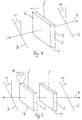
- Figures 3 and 4 show the arrangement of an inventive Interference filter in the application between two glass fibers 10 and 11 or 10 'and 11'.
- the crystal optical interference filter consists of both Figures from a birefringent plate 5 and 5 ', and one each polarizer 6, 6 ', 7, 7' arranged in front or behind.
- the polarizers are, for example, relative, as shown in Figures 1 and 2 oriented to each other and to the axes of the birefringent plate.
- a given spectral light emerges from the ends of the glass fibers 10, 10 ' Composition expanding conically. It is by means of a first lens 8 or 8 'converted into preferably plane waves, wherein then parallel light emerges from the lens. That’s why Fiber end in the area of the focal point of the lens 8 or 8 '.
- the light coupled out on the fiber 10 passes through the interference filter as parallel beam and strikes another at the filter output Lens 9 or 9 ', with which the light returns into the outgoing fiber 11 or 11 'is coupled.
- the end of the fiber 11 or 11 ' is in Area of focus of the lens 9 or 9 '.
- the lenses 8 and 9 from FIG. 3 are infrared-compatible lenses, the lenses 8 'and 9' of Figure 4 are gradient index lenses.
Landscapes
- Physics & Mathematics (AREA)
- General Physics & Mathematics (AREA)
- Optics & Photonics (AREA)
- Nonlinear Science (AREA)
- Crystals, And After-Treatments Of Crystals (AREA)
- Polarising Elements (AREA)
- Inorganic Compounds Of Heavy Metals (AREA)
- Optical Filters (AREA)
- Investigating Or Analysing Materials By Optical Means (AREA)
- Spectrometry And Color Measurement (AREA)
- Lasers (AREA)
Applications Claiming Priority (2)
| Application Number | Priority Date | Filing Date | Title |
|---|---|---|---|
| DE19743716A DE19743716C2 (de) | 1997-10-02 | 1997-10-02 | Kristalloptisches Interferenzfilter mit periodischem Durchlaßbereich sowie Verfahren zur aktiven Anpassung des spektralen Durchlaßbereichs |
| DE19743716 | 1997-10-02 |
Publications (3)
| Publication Number | Publication Date |
|---|---|
| EP0907089A2 true EP0907089A2 (fr) | 1999-04-07 |
| EP0907089A3 EP0907089A3 (fr) | 2000-08-16 |
| EP0907089B1 EP0907089B1 (fr) | 2003-01-22 |
Family
ID=7844487
Family Applications (1)
| Application Number | Title | Priority Date | Filing Date |
|---|---|---|---|
| EP98114521A Expired - Lifetime EP0907089B1 (fr) | 1997-10-02 | 1998-08-03 | Filtre interférentiel à cristal optique avec bande passante périodique et procédé d'adaptation active de la bande passante spectrale |
Country Status (4)
| Country | Link |
|---|---|
| EP (1) | EP0907089B1 (fr) |
| AT (1) | ATE231624T1 (fr) |
| DE (2) | DE19743716C2 (fr) |
| NO (1) | NO984592L (fr) |
Cited By (4)
| Publication number | Priority date | Publication date | Assignee | Title |
|---|---|---|---|---|
| WO2001016647A1 (fr) | 1999-08-30 | 2001-03-08 | Deutsche Telekom Ag | Procede et dispositif pour faire fonctionner de maniere variable avec la temperature des commutateurs electro-optiques a base de cristaux liquides ferroelectriques a structure helicoidale deformee |
| WO2009051464A1 (fr) * | 2007-10-18 | 2009-04-23 | Instituto Nacional De Astrofísica, Óptica Y Electrónica | Filtre biréfringent dans deux longueurs d'onde |
| CN100495118C (zh) * | 2006-03-08 | 2009-06-03 | 中国科学院上海光学精密机械研究所 | 电控超分辨光瞳滤波器 |
| CN118169782A (zh) * | 2023-12-29 | 2024-06-11 | 闽都创新实验室 | 一种卤化汞在双折射率材料中的应用 |
Families Citing this family (1)
| Publication number | Priority date | Publication date | Assignee | Title |
|---|---|---|---|---|
| DE102008048213A1 (de) | 2008-09-20 | 2010-03-25 | Carl Zeiss Microimaging Gmbh | Anordnung zur Verlängerung des Strahlenweges bei optischen Geräten |
Family Cites Families (5)
| Publication number | Priority date | Publication date | Assignee | Title |
|---|---|---|---|---|
| GB1310432A (en) * | 1970-01-26 | 1973-03-21 | Kodak Ltd | Photographic silver halide printing method |
| DE2933858A1 (de) * | 1978-09-23 | 1980-04-03 | Akademija Nauk Ssr | Polarisator |
| US4602342A (en) * | 1983-10-04 | 1986-07-22 | Westinghouse Electric Corp. | Acousto-optic tunable filter |
| US5469279A (en) * | 1989-10-30 | 1995-11-21 | The University Of Colorado Foundation, Inc. | Chiral smectic liquid crystal multipass optical filters including a variable retarder (and a variable isotropic spacer) |
| US5528393A (en) * | 1989-10-30 | 1996-06-18 | Regents Of The University Of Colorado | Split-element liquid crystal tunable optical filter |
-
1997
- 1997-10-02 DE DE19743716A patent/DE19743716C2/de not_active Expired - Lifetime
-
1998
- 1998-08-03 EP EP98114521A patent/EP0907089B1/fr not_active Expired - Lifetime
- 1998-08-03 DE DE59806986T patent/DE59806986D1/de not_active Expired - Lifetime
- 1998-08-03 AT AT98114521T patent/ATE231624T1/de not_active IP Right Cessation
- 1998-10-01 NO NO984592A patent/NO984592L/no not_active Application Discontinuation
Cited By (5)
| Publication number | Priority date | Publication date | Assignee | Title |
|---|---|---|---|---|
| WO2001016647A1 (fr) | 1999-08-30 | 2001-03-08 | Deutsche Telekom Ag | Procede et dispositif pour faire fonctionner de maniere variable avec la temperature des commutateurs electro-optiques a base de cristaux liquides ferroelectriques a structure helicoidale deformee |
| US6900874B1 (en) | 1999-08-30 | 2005-05-31 | Deutsche Telekom Ag | Device and method for the temperature-independent operation of electro-optical switches on the basis of ferroelectric liquid crystals having a deformed helix |
| CN100495118C (zh) * | 2006-03-08 | 2009-06-03 | 中国科学院上海光学精密机械研究所 | 电控超分辨光瞳滤波器 |
| WO2009051464A1 (fr) * | 2007-10-18 | 2009-04-23 | Instituto Nacional De Astrofísica, Óptica Y Electrónica | Filtre biréfringent dans deux longueurs d'onde |
| CN118169782A (zh) * | 2023-12-29 | 2024-06-11 | 闽都创新实验室 | 一种卤化汞在双折射率材料中的应用 |
Also Published As
| Publication number | Publication date |
|---|---|
| NO984592L (no) | 1999-04-06 |
| EP0907089A3 (fr) | 2000-08-16 |
| NO984592D0 (no) | 1998-10-01 |
| EP0907089B1 (fr) | 2003-01-22 |
| DE19743716A1 (de) | 1999-04-29 |
| DE59806986D1 (de) | 2003-02-27 |
| ATE231624T1 (de) | 2003-02-15 |
| DE19743716C2 (de) | 2000-09-07 |
Similar Documents
| Publication | Publication Date | Title |
|---|---|---|
| DE68918764T2 (de) | Wellenlängenmultiplexermodul. | |
| DE4029626C2 (de) | Optische Logikvorrichtungen | |
| DE3209927C2 (fr) | ||
| DE69202993T2 (de) | Elektrisch steuerbares, wellenlängenselektives Filter. | |
| DE69025904T2 (de) | Optischer Faserfilter | |
| DE19823849B4 (de) | Verfahren und Vorrichtung zur Erzeugung von wahlweise Einzelphotonen oder Photonenpaaren in mindestens einem von zwei optischen Kanälen | |
| DE69019576T2 (de) | Optischer Multiplexer/Demultiplexer mit fokussierenden Bragg-Reflektoren. | |
| DE69731500T2 (de) | Akustooptische Wellenleitervorrichtung mit Kompensation der Polarisationsmodendispersion | |
| DE69321154T2 (de) | Durch Rotation abstimmbares Fabry-Perot-Interferometor enthaltendes optisches Filter | |
| DE2804105C2 (fr) | ||
| DE3687272T2 (de) | Optischer leistungsteiler und polarisationsteiler. | |
| DE2258215A1 (de) | Selektive optische koppelvorrichtung | |
| DE4304685A1 (fr) | ||
| EP0740173A2 (fr) | Structure de circuit pour compenser la dispersion dans les systèmes de télécommunications optiques au moyen d'un filtre optique | |
| DE2908752A1 (de) | Optisches transmissionsfilter | |
| DE60017412T2 (de) | Dichter wellenlängenmultiplexer hoher isolation mit polarisationsstrahlteiler, nichtlinearem interferometer und doppelbrechenden platten | |
| DE2804363C2 (de) | Anordnung zur Lichtmodulation von über einen optischen Wellenleiter übertragenem Licht | |
| EP2478400A2 (fr) | Filtres de modes transversaux pour guide d'onde | |
| EP0907089B1 (fr) | Filtre interférentiel à cristal optique avec bande passante périodique et procédé d'adaptation active de la bande passante spectrale | |
| DE69109433T2 (de) | Wellenlängenfilter in Form eines optischen Wellenleiters. | |
| DE60115525T2 (de) | Polarisierendes doppelbrechendes Filter mit Doppeldurchgang | |
| DE10122010A1 (de) | Anordnung zum Multiplexing und/oder Demultiplexing | |
| DE10146006A1 (de) | Verfahren zur Temperaturkompensation einer optischen WDM-Komponente sowie optische WDM-Komponente mit Temperaturkompensation | |
| DE10225176C1 (de) | Vorrichtung zum Demultiplexen optischer Signale einer Vielzahl von Wellenlängen | |
| DE3528294A1 (de) | Verfahren zur faseroptischen, spektral kodierten uebertragung des wertes einer veraenderlichen physikalischen messgroesse |
Legal Events
| Date | Code | Title | Description |
|---|---|---|---|
| PUAI | Public reference made under article 153(3) epc to a published international application that has entered the european phase |
Free format text: ORIGINAL CODE: 0009012 |
|
| AK | Designated contracting states |
Kind code of ref document: A2 Designated state(s): AT BE DE DK ES FI FR GB GR IE IT LU NL PT SE |
|
| AX | Request for extension of the european patent |
Free format text: AL;LT;LV;MK;RO;SI |
|
| PUAL | Search report despatched |
Free format text: ORIGINAL CODE: 0009013 |
|
| RIC1 | Information provided on ipc code assigned before grant |
Free format text: 7G 02B 5/28 A, 7G 02B 27/28 B |
|
| AK | Designated contracting states |
Kind code of ref document: A3 Designated state(s): AT BE CH CY DE DK ES FI FR GB GR IE IT LI LU MC NL PT SE |
|
| AX | Request for extension of the european patent |
Free format text: AL;LT;LV;MK;RO;SI |
|
| 17P | Request for examination filed |
Effective date: 20010216 |
|
| 17Q | First examination report despatched |
Effective date: 20010321 |
|
| AKX | Designation fees paid |
Free format text: AT BE DE DK ES FI FR GB GR IE IT LU NL PT SE |
|
| GRAG | Despatch of communication of intention to grant |
Free format text: ORIGINAL CODE: EPIDOS AGRA |
|
| GRAG | Despatch of communication of intention to grant |
Free format text: ORIGINAL CODE: EPIDOS AGRA |
|
| GRAH | Despatch of communication of intention to grant a patent |
Free format text: ORIGINAL CODE: EPIDOS IGRA |
|
| GRAH | Despatch of communication of intention to grant a patent |
Free format text: ORIGINAL CODE: EPIDOS IGRA |
|
| GRAA | (expected) grant |
Free format text: ORIGINAL CODE: 0009210 |
|
| AK | Designated contracting states |
Kind code of ref document: B1 Designated state(s): AT BE DE DK ES FI FR GB GR IE IT LU NL PT SE |
|
| PG25 | Lapsed in a contracting state [announced via postgrant information from national office to epo] |
Ref country code: IE Free format text: LAPSE BECAUSE OF FAILURE TO SUBMIT A TRANSLATION OF THE DESCRIPTION OR TO PAY THE FEE WITHIN THE PRESCRIBED TIME-LIMIT Effective date: 20030122 Ref country code: GR Free format text: LAPSE BECAUSE OF FAILURE TO SUBMIT A TRANSLATION OF THE DESCRIPTION OR TO PAY THE FEE WITHIN THE PRESCRIBED TIME-LIMIT Effective date: 20030122 Ref country code: FI Free format text: LAPSE BECAUSE OF FAILURE TO SUBMIT A TRANSLATION OF THE DESCRIPTION OR TO PAY THE FEE WITHIN THE PRESCRIBED TIME-LIMIT Effective date: 20030122 |
|
| REG | Reference to a national code |
Ref country code: GB Ref legal event code: FG4D Free format text: NOT ENGLISH |
|
| REG | Reference to a national code |
Ref country code: IE Ref legal event code: FG4D Free format text: GERMAN |
|
| REF | Corresponds to: |
Ref document number: 59806986 Country of ref document: DE Date of ref document: 20030227 Kind code of ref document: P |
|
| PG25 | Lapsed in a contracting state [announced via postgrant information from national office to epo] |
Ref country code: SE Free format text: LAPSE BECAUSE OF FAILURE TO SUBMIT A TRANSLATION OF THE DESCRIPTION OR TO PAY THE FEE WITHIN THE PRESCRIBED TIME-LIMIT Effective date: 20030422 Ref country code: PT Free format text: LAPSE BECAUSE OF FAILURE TO SUBMIT A TRANSLATION OF THE DESCRIPTION OR TO PAY THE FEE WITHIN THE PRESCRIBED TIME-LIMIT Effective date: 20030422 Ref country code: DK Free format text: LAPSE BECAUSE OF FAILURE TO SUBMIT A TRANSLATION OF THE DESCRIPTION OR TO PAY THE FEE WITHIN THE PRESCRIBED TIME-LIMIT Effective date: 20030422 |
|
| GBT | Gb: translation of ep patent filed (gb section 77(6)(a)/1977) |
Effective date: 20030519 |
|
| PG25 | Lapsed in a contracting state [announced via postgrant information from national office to epo] |
Ref country code: ES Free format text: LAPSE BECAUSE OF FAILURE TO SUBMIT A TRANSLATION OF THE DESCRIPTION OR TO PAY THE FEE WITHIN THE PRESCRIBED TIME-LIMIT Effective date: 20030730 |
|
| PG25 | Lapsed in a contracting state [announced via postgrant information from national office to epo] |
Ref country code: LU Free format text: LAPSE BECAUSE OF NON-PAYMENT OF DUE FEES Effective date: 20030803 Ref country code: AT Free format text: LAPSE BECAUSE OF NON-PAYMENT OF DUE FEES Effective date: 20030803 |
|
| REG | Reference to a national code |
Ref country code: IE Ref legal event code: FD4D Ref document number: 0907089E Country of ref document: IE |
|
| PG25 | Lapsed in a contracting state [announced via postgrant information from national office to epo] |
Ref country code: BE Free format text: LAPSE BECAUSE OF NON-PAYMENT OF DUE FEES Effective date: 20030831 |
|
| ET | Fr: translation filed | ||
| PLBE | No opposition filed within time limit |
Free format text: ORIGINAL CODE: 0009261 |
|
| STAA | Information on the status of an ep patent application or granted ep patent |
Free format text: STATUS: NO OPPOSITION FILED WITHIN TIME LIMIT |
|
| 26N | No opposition filed |
Effective date: 20031023 |
|
| BERE | Be: lapsed |
Owner name: DEUTSCHE *TELEKOM A.G. Effective date: 20030831 |
|
| PGFP | Annual fee paid to national office [announced via postgrant information from national office to epo] |
Ref country code: NL Payment date: 20100823 Year of fee payment: 13 |
|
| PGFP | Annual fee paid to national office [announced via postgrant information from national office to epo] |
Ref country code: IT Payment date: 20100825 Year of fee payment: 13 Ref country code: FR Payment date: 20100901 Year of fee payment: 13 |
|
| PGFP | Annual fee paid to national office [announced via postgrant information from national office to epo] |
Ref country code: GB Payment date: 20100823 Year of fee payment: 13 |
|
| PGFP | Annual fee paid to national office [announced via postgrant information from national office to epo] |
Ref country code: DE Payment date: 20100922 Year of fee payment: 13 |
|
| REG | Reference to a national code |
Ref country code: NL Ref legal event code: V1 Effective date: 20120301 |
|
| GBPC | Gb: european patent ceased through non-payment of renewal fee |
Effective date: 20110803 |
|
| REG | Reference to a national code |
Ref country code: FR Ref legal event code: ST Effective date: 20120430 |
|
| PG25 | Lapsed in a contracting state [announced via postgrant information from national office to epo] |
Ref country code: IT Free format text: LAPSE BECAUSE OF NON-PAYMENT OF DUE FEES Effective date: 20110803 Ref country code: NL Free format text: LAPSE BECAUSE OF NON-PAYMENT OF DUE FEES Effective date: 20120301 |
|
| REG | Reference to a national code |
Ref country code: DE Ref legal event code: R119 Ref document number: 59806986 Country of ref document: DE Effective date: 20120301 |
|
| PG25 | Lapsed in a contracting state [announced via postgrant information from national office to epo] |
Ref country code: GB Free format text: LAPSE BECAUSE OF NON-PAYMENT OF DUE FEES Effective date: 20110803 Ref country code: FR Free format text: LAPSE BECAUSE OF NON-PAYMENT OF DUE FEES Effective date: 20110831 |
|
| PG25 | Lapsed in a contracting state [announced via postgrant information from national office to epo] |
Ref country code: DE Free format text: LAPSE BECAUSE OF NON-PAYMENT OF DUE FEES Effective date: 20120301 |