EP0907065A2 - Lock for holding a magazine in a gun - Google Patents
Lock for holding a magazine in a gun Download PDFInfo
- Publication number
- EP0907065A2 EP0907065A2 EP98810906A EP98810906A EP0907065A2 EP 0907065 A2 EP0907065 A2 EP 0907065A2 EP 98810906 A EP98810906 A EP 98810906A EP 98810906 A EP98810906 A EP 98810906A EP 0907065 A2 EP0907065 A2 EP 0907065A2
- Authority
- EP
- European Patent Office
- Prior art keywords
- magazine
- housing
- arm
- opening
- engages
- Prior art date
- Legal status (The legal status is an assumption and is not a legal conclusion. Google has not performed a legal analysis and makes no representation as to the accuracy of the status listed.)
- Withdrawn
Links
- 230000006835 compression Effects 0.000 description 1
- 238000007906 compression Methods 0.000 description 1
- 230000037431 insertion Effects 0.000 description 1
- 238000003780 insertion Methods 0.000 description 1
- 210000003813 thumb Anatomy 0.000 description 1
- 210000001364 upper extremity Anatomy 0.000 description 1
Images
Classifications
-
- F—MECHANICAL ENGINEERING; LIGHTING; HEATING; WEAPONS; BLASTING
- F41—WEAPONS
- F41A—FUNCTIONAL FEATURES OR DETAILS COMMON TO BOTH SMALLARMS AND ORDNANCE, e.g. CANNONS; MOUNTINGS FOR SMALLARMS OR ORDNANCE
- F41A17/00—Safety arrangements, e.g. safeties
- F41A17/34—Magazine safeties
- F41A17/38—Magazine mountings, e.g. for locking the magazine in the gun
Definitions
- Magazine locks are usually one-sided in a housing attached with a magazine opening.
- a magazine lock is disclosed in U.S. Patent No. 2,632,272 known to a rifle.
- the magazine has one on the front Cam that is in a corresponding recess in the magazine shaft is used. Then the magazine is towards the back panned.
- the rear edge of the magazine has a projection who presses a locking lever when swinging the magazine in and snaps behind this after insertion.
- an additional fuse is provided on the cam side, to prevent the magazine from being pushed in, if the weapon is not ready for use.
- the present invention has for its object a safe Magazine lock also for relatively short magazines to reach. This task is accomplished through the combination of features of claim 1 solved.
- the magazine lock shown comprises a housing 1 with a magazine opening 2 and a trigger guard 3, in which in assembled state a trigger tongue protrudes.
- a magazine 4 is inserted in the magazine opening 2 .
- the magazine 4 has on the front wall and a rectangular recess 5, 6 on the rear wall.
- the magazine bottom 4a projects above the magazine opening 2.
- a two-armed locking lever 7 pivotally mounted on a cylindrical pin 8.
- the cylinder pin 8 is pressed into a bore 9 of the housing 1.
- the first arm 10 of the locking lever 7 stands within the trigger guard 3 in front and has a ribbed grip surface 11 for actuation with the thumb.
- the second arm 12 of the locking lever 7 has one Stop surface 13, which when the magazine 4 is not inserted strikes a shoulder 14 of the housing 1.
- the first arm 10 is through a preloaded compression spring 16 loaded on the housing 1 is supported.
- the locking lever 7 is in a groove 17 of the housing 1 led.
- the magazine lock described locks the magazine 4 on two opposite narrow sides at the same time and requires therefore just a very short guide in the magazine opening 2. It therefore has a low overall height and is also suitable for very short magazines 4 for just a few cartridges. it is very easy and ergonomic to use.
Landscapes
- Engineering & Computer Science (AREA)
- General Engineering & Computer Science (AREA)
- Portable Nailing Machines And Staplers (AREA)
- Buckles (AREA)
- Toys (AREA)
Abstract
Die Magazin-Arretierung umfasst ein Gehäuse (1) mit einer Magazinöffnung
(2) und einem Abzugbügel (3). Im Gehäuse (1) ist ein
doppelarmiger, federbelasteter Arretierhebel (7) schwenkbar gelagert.
Dessen erster Arm (10) steht innerhalb des Abzugbügels
(3) zur Betätigung vor. Der zweite Arm (12) des Hebels (7)
greift in eine Öffnung (6) des Magazins (4). Am ersten Arm (10)
ist ein Schieber (24) angelenkt, der die Magazinöffnung (2) umgreift.
Der Schieber (24) hat auf der gegenüberliegenden zweiten
Seite des Magazins (4) einen Stift (28), der in eine zweite Ausnehmung
(5) auf der gegenüberliegenden Seite des Magazins (4)
eingreift. Dadurch wird eine sichere Arretierung des Magazins
bei geringer Bauhöhe erreicht.

Description
Magazin-Arretierungen sind gewöhnlich einseitig in einem Gehäuse mit einer Magazinöffnung angebracht.Magazine locks are usually one-sided in a housing attached with a magazine opening.
Aus dem US-Patent Nr. 2 632 272 ist eine Magazin-Arretierung an einem Gewehr bekannt. Das Magazin hat auf der Vorderseite einen Nocken, der in eine entsprechende Ausnehmung im Magazinschacht eingesetzt wird. Anschliessend wird das Magazin gegen hinten verschwenkt. Der hintere Rand des Magazins hat einen Vorsprung, der beim Einschwenken des Magazins einen Rasthebel eindrückt und nach dem Einsetzen hinter diesem einschnappt. Im Magazinschacht ist auf der Nockenseite eine zusätzliche Sicherung vorgesehen, die verhindern soll, dass das Magazin eingeschoben werden kann, wenn die Waffe nicht betriebsbereit ist.A magazine lock is disclosed in U.S. Patent No. 2,632,272 known to a rifle. The magazine has one on the front Cam that is in a corresponding recess in the magazine shaft is used. Then the magazine is towards the back panned. The rear edge of the magazine has a projection who presses a locking lever when swinging the magazine in and snaps behind this after insertion. In the magazine shaft an additional fuse is provided on the cam side, to prevent the magazine from being pushed in, if the weapon is not ready for use.
Der vorliegenden Erfindung liegt die Aufgabe zugrunde, eine sichere Magazin-Arretierung auch für relativ kurz geführte Magazine zu erreichen. Diese Aufgabe wird durch die Merkmalskombination des Anspruchs 1 gelöst.The present invention has for its object a safe Magazine lock also for relatively short magazines to reach. This task is accomplished through the combination of features of claim 1 solved.
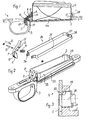
Nachfolgend wird ein Ausführungsbeispiel der Erfindung anhand der Zeichnung erläutert. Darin zeigt:
- Figur 1
- einen Vertikalschnitt durch eine Magazin-Arretierung,
Figur 2- eine Explosionsdarstellung der Teile der Arretierung, und
Figur 3- das Detail X von Figur 1 in vergrössertem Massstab.
- Figure 1
- a vertical section through a magazine lock,
- Figure 2
- an exploded view of the parts of the lock, and
- Figure 3
- the detail X of Figure 1 on an enlarged scale.
Die dargestellte Magazin-Arretierung umfasst ein Gehäuse 1 mit
einer Magazinöffnung 2 und einem Abzugbügel 3, in welchen im
montierten Zustand eine Abzugzunge ragt. In die Magazinöffnung 2
ist ein Magazin 4 eingeschoben. Das Magazin 4 hat an der Vorderwand
und an der Rückwand je eine rechteckige Ausnehmung 5, 6.
Der Magazinboden 4a überragt die Magazinöffnung 2. Am vorderen
Schenkel des Abzugbügels 3 ist ein zweiarmiger Arretierhebel 7
auf einem Zylinderstift 8 schwenkbar gelagert. Der Zylinderstift
8 ist in eine Bohrung 9 des Gehäuses 1 eingepresst. Der
erste Arm 10 des Arretierhebels 7 steht innerhalb des Abzugbügels
3 vor und hat eine gerippte Grifffläche 11 zur Betätigung
mit dem Daumen. Der zweite Arm 12 des Arretierhebels 7 hat eine
Anschlagfläche 13, welche bei nicht eingesetztem Magazin 4 an
einer Schulter 14 des Gehäuses 1 anschlägt. Am freien Ende hat
der nach schräg oben abstehende zweite Arm 12 eine Rastkerbe 15,
die in der Ausnehmung 6 einrastet. Der erste Arm 10 ist durch
eine vorgespannte Druckfeder 16 belastet, welche am Gehäuse 1
abgestützt ist. Der Arretierhebel 7 ist in einer Nut 17 des Gehäuses
1 geführt.The magazine lock shown comprises a housing 1 with
a magazine opening 2 and a
Am ersten Arm 10 ist beabstandet vom Zylinderstift 8 ein zweiter
Zylinderstift 21 eingesetzt. Die beiden Seitenwände 22 der Magazinöffnung
2 haben je eine Längsnut 23. In diesen Längsnuten 23
ist ein U-förmiger Schieber 24 eingesetzt und geführt. Der
Schieber 24 hat an den freien Enden seiner Schenkel 25 zwei sich
quer zu dessen Längserstreckung erstreckende Langlöcher 26. Der
Zylinderstift 21 durchgreift diese Langlöcher 26, so dass beim
Drücken des Arms 10 des Arretierhebels 7 der Schieber 24 nach
vorn bewegt wird. In einen Steg 27 des Schiebers 24 ist ein zylindrischer
Stift 28 eingenietet. Der Stift 28 ist in einer Bohrung
29 des Gehäuses 1 geführt und hat oben eine Abflachung 30,
welche in den oberen Rand der Ausnehmung 5 einrastet. Das freie
Ende des Stiftes 28 ist konisch angeschrägt, damit der Stift 28
beim Einschieben des Magazins 4 eingedrückt wird. Alternativ
könnte am unteren Rand des Stiftes 28 auch eine Keilfläche geschliffen
sein. On the
Die beschriebene Magazin-Arretierung arretiert das Magazin 4 auf
zwei gegenüberliegenden Schmalseiten gleichzeitig und erfordert
deshalb bloss eine sehr kurze Führung in der Magazinöffnung 2.
Sie hat daher eine niedrige Bauhöhe und eignet sich auch für
sehr kurze Magazine 4 für bloss wenige Patronen. Sie ist sehr
einfach und ergonomisch zu bedienen.The magazine lock described locks the
Claims (6)
Applications Claiming Priority (2)
| Application Number | Priority Date | Filing Date | Title |
|---|---|---|---|
| DE19743557A DE19743557C1 (en) | 1997-10-01 | 1997-10-01 | Magazine holder for rifle |
| DE19743557 | 1997-10-01 |
Publications (2)
| Publication Number | Publication Date |
|---|---|
| EP0907065A2 true EP0907065A2 (en) | 1999-04-07 |
| EP0907065A3 EP0907065A3 (en) | 1999-08-04 |
Family
ID=7844383
Family Applications (1)
| Application Number | Title | Priority Date | Filing Date |
|---|---|---|---|
| EP98810906A Withdrawn EP0907065A3 (en) | 1997-10-01 | 1998-09-11 | Lock for holding a magazine in a gun |
Country Status (3)
| Country | Link |
|---|---|
| US (1) | US5899013A (en) |
| EP (1) | EP0907065A3 (en) |
| DE (1) | DE19743557C1 (en) |
Cited By (2)
| Publication number | Priority date | Publication date | Assignee | Title |
|---|---|---|---|---|
| US7963062B1 (en) | 2006-03-03 | 2011-06-21 | S.A.T. Swiss Arms Technology Ag | Insertion magazine for a small arm |
| US8438768B2 (en) | 2011-01-07 | 2013-05-14 | Sturm, Ruger & Company, Inc. | Magazine disconnect mechanism for firearm |
Families Citing this family (17)
| Publication number | Priority date | Publication date | Assignee | Title |
|---|---|---|---|---|
| US20040154207A1 (en) * | 2003-02-12 | 2004-08-12 | Kenneth Conner | Gun magazine with leaf spring |
| US7225575B2 (en) * | 2003-07-01 | 2007-06-05 | Sigarms, Inc. | Method and device for providing an integral firearms safety lock mechanism |
| FI118160B (en) * | 2005-09-23 | 2007-07-31 | Sako Oy | Locking device for a weapons magazine |
| EP2195599B1 (en) * | 2007-08-30 | 2013-01-09 | Ra Brands, L.L.C. | Pivoting, non-detachable magazine |
| US8434253B2 (en) * | 2010-03-29 | 2013-05-07 | Randy Cain | Magazine release latch and trigger guard |
| US9766029B2 (en) * | 2011-07-12 | 2017-09-19 | Cadex, Inc. | Detachable chassis base for rifle |
| USD693421S1 (en) * | 2012-03-28 | 2013-11-12 | Raul Delgado Acarreta | Adapter for firearms |
| US9513077B2 (en) * | 2013-01-11 | 2016-12-06 | Howa Machnery, Ltd. | Magazine lock and portable firearm |
| US9689632B2 (en) * | 2014-05-06 | 2017-06-27 | Hawkins Precision LLC | Integral spring bottom metal latch |
| NO2751115T3 (en) * | 2014-09-15 | 2018-02-17 | ||
| US9482478B2 (en) * | 2014-12-12 | 2016-11-01 | Dark Storm Industries, LLC | Non-detachable magazine lower receiver |
| US9803943B2 (en) | 2015-03-06 | 2017-10-31 | Iron Claw Tactical LLC | Firearm magazine guidance and ejection device |
| US9482481B2 (en) * | 2015-07-22 | 2016-11-01 | Seven Six Two Systems | Push-lever magazine release for converting a carbine from clamshell magazines to removable magazines |
| US10101102B2 (en) | 2015-07-31 | 2018-10-16 | Magpul Industries Corp. | Magazine well for a firearm |
| US10697724B2 (en) * | 2017-05-16 | 2020-06-30 | RedSnake Enterprises, LLC | Bottom metal for a detachable box magazine |
| USD897479S1 (en) * | 2019-01-21 | 2020-09-29 | Daniel Defense, Inc. | Trigger guard and magazine latch assembly |
| US11421956B1 (en) | 2021-02-10 | 2022-08-23 | WHG Properties, LLC | Firearm assemblies with a trigger guard magazine guide portion |
Citations (1)
| Publication number | Priority date | Publication date | Assignee | Title |
|---|---|---|---|---|
| US2632272A (en) | 1949-04-29 | 1953-03-24 | Zbrojovka Brno Np | Firearm safety device |
Family Cites Families (11)
| Publication number | Priority date | Publication date | Assignee | Title |
|---|---|---|---|---|
| US2386722A (en) * | 1944-09-29 | 1945-10-09 | Olin Ind Inc | Box magazine latch mechanism for repeating firearms |
| US2657489A (en) * | 1950-04-03 | 1953-11-03 | Jr Leonard Franklin Robertson | Magazine floor plate release mechanism |
| US2736977A (en) * | 1953-04-17 | 1956-03-06 | Earle M Harvey | Magazine latching means |
| US2956363A (en) * | 1959-06-23 | 1960-10-18 | Alfred L Montana | Side cam magazine catch for firearms |
| US3088378A (en) * | 1960-07-05 | 1963-05-07 | John L Boudreau | Pistol with slidable and fixed breech block |
| US3574264A (en) * | 1969-07-14 | 1971-04-13 | Ernest P Simmons Sr | Magazine assembly for automatic rifles |
| DE2014328C3 (en) * | 1970-03-25 | 1975-11-13 | Rheinmetall Gmbh, 4000 Duesseldorf | Magazine holder and release mechanism on handguns |
| US4237638A (en) * | 1978-08-04 | 1980-12-09 | Trexler Gene D | Box magazine replacement kit for bolt action rifles |
| DE3136965A1 (en) * | 1981-09-17 | 1983-03-31 | Galan, Pierre, 92600 Asnières | Repeater rifle, especially for sporting purposes |
| US4815226A (en) * | 1987-12-31 | 1989-03-28 | Sturm, Ruger & Company, Inc. | Rifle floor plate latch |
| US5519954A (en) * | 1995-06-19 | 1996-05-28 | Garrett; Robert H. | Ambidextrous magazine release mechanism for firearms |
-
1997
- 1997-10-01 DE DE19743557A patent/DE19743557C1/en not_active Expired - Fee Related
-
1998
- 1998-09-11 EP EP98810906A patent/EP0907065A3/en not_active Withdrawn
- 1998-09-21 US US09/157,907 patent/US5899013A/en not_active Expired - Fee Related
Patent Citations (1)
| Publication number | Priority date | Publication date | Assignee | Title |
|---|---|---|---|---|
| US2632272A (en) | 1949-04-29 | 1953-03-24 | Zbrojovka Brno Np | Firearm safety device |
Cited By (2)
| Publication number | Priority date | Publication date | Assignee | Title |
|---|---|---|---|---|
| US7963062B1 (en) | 2006-03-03 | 2011-06-21 | S.A.T. Swiss Arms Technology Ag | Insertion magazine for a small arm |
| US8438768B2 (en) | 2011-01-07 | 2013-05-14 | Sturm, Ruger & Company, Inc. | Magazine disconnect mechanism for firearm |
Also Published As
| Publication number | Publication date |
|---|---|
| US5899013A (en) | 1999-05-04 |
| DE19743557C1 (en) | 1999-03-25 |
| EP0907065A3 (en) | 1999-08-04 |
Similar Documents
| Publication | Publication Date | Title |
|---|---|---|
| DE19743557C1 (en) | Magazine holder for rifle | |
| EP1830152B1 (en) | Pluggable magazine for a handgun | |
| EP1277022A1 (en) | Bottom of a pistol magazine | |
| WO1996007866A1 (en) | Magazine | |
| DE19737153A1 (en) | Trigger for hunting rifle with bayonet catch | |
| DE69407416T2 (en) | FIREARMS WITH JOINT MAGAZINE | |
| EP1692452B1 (en) | Pistol with cartridge magazine | |
| DE1429912A1 (en) | Container with detachable handle | |
| WO2023104548A1 (en) | Rifle with a breech catching device | |
| DE10323338B4 (en) | A rifle comprising a buttstock and a barrel detachable from the buttstock | |
| EP2966397A1 (en) | Gas pressure rifle | |
| CH622342A5 (en) | ||
| EP4038333B1 (en) | Carbine having a charging handle | |
| DE102004063966B4 (en) | Handgun for sporting shooting | |
| EP3096107B1 (en) | Breech mechanism for a rifle | |
| DE602005004407T2 (en) | MAGAZINE ASSURANCE FOR SMALL FIREARMS, ESPECIALLY SELF-LOADING PISTOLS | |
| EP1597530B1 (en) | Trigger system for small arms | |
| DE2225335A1 (en) | AIR RIFLE WITH A CASE AND A SAFETY DEVICE | |
| DE2849843C2 (en) | ||
| DE10211882A1 (en) | Safety device for long-barrel weapon with striker bolt lock has locking shaft which can be arrested in its weapon-secured position | |
| WO2001007859A1 (en) | Holder for a weapon, especially for a handgun | |
| DE202017103628U1 (en) | Pistol for dowels | |
| DE1428621C3 (en) | Pressure point trigger, especially for compressed air guns | |
| DE10325457A1 (en) | scraper | |
| AT515524B1 (en) | Handgun |
Legal Events
| Date | Code | Title | Description |
|---|---|---|---|
| PUAI | Public reference made under article 153(3) epc to a published international application that has entered the european phase |
Free format text: ORIGINAL CODE: 0009012 |
|
| AK | Designated contracting states |
Kind code of ref document: A2 Designated state(s): AT CH DE FR IT LI |
|
| AX | Request for extension of the european patent |
Free format text: AL;LT;LV;MK;RO;SI |
|
| PUAL | Search report despatched |
Free format text: ORIGINAL CODE: 0009013 |
|
| AK | Designated contracting states |
Kind code of ref document: A3 Designated state(s): AT BE CH CY DE DK ES FI FR GB GR IE IT LI LU MC NL PT SE |
|
| AX | Request for extension of the european patent |
Free format text: AL;LT;LV;MK;RO;SI |
|
| 17P | Request for examination filed |
Effective date: 19991208 |
|
| AKX | Designation fees paid |
Free format text: AT CH DE FR IT LI |
|
| 17Q | First examination report despatched |
Effective date: 20020130 |
|
| RAP1 | Party data changed (applicant data changed or rights of an application transferred) |
Owner name: S.A.T. SWISS ARMS TECHNOLOGY AG |
|
| STAA | Information on the status of an ep patent application or granted ep patent |
Free format text: STATUS: THE APPLICATION IS DEEMED TO BE WITHDRAWN |
|
| 18D | Application deemed to be withdrawn |
Effective date: 20021121 |