EP0906881A1 - Vereinzelungsgerät für ein Posthandhabungssystem - Google Patents
Vereinzelungsgerät für ein Posthandhabungssystem Download PDFInfo
- Publication number
- EP0906881A1 EP0906881A1 EP98118650A EP98118650A EP0906881A1 EP 0906881 A1 EP0906881 A1 EP 0906881A1 EP 98118650 A EP98118650 A EP 98118650A EP 98118650 A EP98118650 A EP 98118650A EP 0906881 A1 EP0906881 A1 EP 0906881A1
- Authority
- EP
- European Patent Office
- Prior art keywords
- articles
- nip
- feed
- stack
- force
- Prior art date
- Legal status (The legal status is an assumption and is not a legal conclusion. Google has not performed a legal analysis and makes no representation as to the accuracy of the status listed.)
- Granted
Links
- 230000007246 mechanism Effects 0.000 claims abstract description 23
- 230000037406 food intake Effects 0.000 claims description 13
- 238000000034 method Methods 0.000 claims description 6
- 230000009471 action Effects 0.000 claims description 4
- 229910001220 stainless steel Inorganic materials 0.000 claims description 2
- 239000010935 stainless steel Substances 0.000 claims description 2
- 238000012545 processing Methods 0.000 description 16
- 238000000926 separation method Methods 0.000 description 9
- 238000000418 atomic force spectrum Methods 0.000 description 8
- 230000000712 assembly Effects 0.000 description 5
- 238000000429 assembly Methods 0.000 description 5
- 230000008901 benefit Effects 0.000 description 5
- 230000000903 blocking effect Effects 0.000 description 5
- 230000033001 locomotion Effects 0.000 description 5
- 230000032258 transport Effects 0.000 description 5
- 230000008569 process Effects 0.000 description 4
- 238000013461 design Methods 0.000 description 3
- 230000001105 regulatory effect Effects 0.000 description 3
- 238000011144 upstream manufacturing Methods 0.000 description 3
- XAGFODPZIPBFFR-UHFFFAOYSA-N aluminium Chemical compound [Al] XAGFODPZIPBFFR-UHFFFAOYSA-N 0.000 description 2
- 229910052782 aluminium Inorganic materials 0.000 description 2
- 230000003993 interaction Effects 0.000 description 2
- 239000000463 material Substances 0.000 description 2
- 238000012986 modification Methods 0.000 description 2
- 230000004048 modification Effects 0.000 description 2
- 230000004044 response Effects 0.000 description 2
- 239000000758 substrate Substances 0.000 description 2
- JOYRKODLDBILNP-UHFFFAOYSA-N Ethyl urethane Chemical compound CCOC(N)=O JOYRKODLDBILNP-UHFFFAOYSA-N 0.000 description 1
- 230000003466 anti-cipated effect Effects 0.000 description 1
- 238000004891 communication Methods 0.000 description 1
- 230000006835 compression Effects 0.000 description 1
- 238000007906 compression Methods 0.000 description 1
- 230000001419 dependent effect Effects 0.000 description 1
- 238000012360 testing method Methods 0.000 description 1
Images


Classifications
-
- B—PERFORMING OPERATIONS; TRANSPORTING
- B65—CONVEYING; PACKING; STORING; HANDLING THIN OR FILAMENTARY MATERIAL
- B65H—HANDLING THIN OR FILAMENTARY MATERIAL, e.g. SHEETS, WEBS, CABLES
- B65H3/00—Separating articles from piles
- B65H3/46—Supplementary devices or measures to assist separation or prevent double feed
- B65H3/52—Friction retainers acting on under or rear side of article being separated
- B65H3/5246—Driven retainers, i.e. the motion thereof being provided by a dedicated drive
-
- B—PERFORMING OPERATIONS; TRANSPORTING
- B65—CONVEYING; PACKING; STORING; HANDLING THIN OR FILAMENTARY MATERIAL
- B65H—HANDLING THIN OR FILAMENTARY MATERIAL, e.g. SHEETS, WEBS, CABLES
- B65H2511/00—Dimensions; Position; Numbers; Identification; Occurrences
- B65H2511/10—Size; Dimensions
- B65H2511/13—Thickness
-
- B—PERFORMING OPERATIONS; TRANSPORTING
- B65—CONVEYING; PACKING; STORING; HANDLING THIN OR FILAMENTARY MATERIAL
- B65H—HANDLING THIN OR FILAMENTARY MATERIAL, e.g. SHEETS, WEBS, CABLES
- B65H2511/00—Dimensions; Position; Numbers; Identification; Occurrences
- B65H2511/50—Occurence
- B65H2511/51—Presence
-
- B—PERFORMING OPERATIONS; TRANSPORTING
- B65—CONVEYING; PACKING; STORING; HANDLING THIN OR FILAMENTARY MATERIAL
- B65H—HANDLING THIN OR FILAMENTARY MATERIAL, e.g. SHEETS, WEBS, CABLES
- B65H2515/00—Physical entities not provided for in groups B65H2511/00 or B65H2513/00
- B65H2515/30—Forces; Stresses
- B65H2515/34—Pressure, e.g. fluid pressure
-
- B—PERFORMING OPERATIONS; TRANSPORTING
- B65—CONVEYING; PACKING; STORING; HANDLING THIN OR FILAMENTARY MATERIAL
- B65H—HANDLING THIN OR FILAMENTARY MATERIAL, e.g. SHEETS, WEBS, CABLES
- B65H2701/00—Handled material; Storage means
- B65H2701/10—Handled articles or webs
- B65H2701/19—Specific article or web
- B65H2701/1916—Envelopes and articles of mail
Definitions
- the processing and handling of mailpieces consumes an enormous amount of human and financial resources, particularly if the processing of the mailpieces is done manually.
- the processing and handling of mailpieces not only takes place at the Postal Service, but also occurs at each and every business or other site where communication via the mail delivery system is utilized. That is, various pieces of mail generated by a plurality of departments and individuals within a company need to be collected, sorted, addressed, and franked as part of the outgoing mail process. Additionally, incoming mail needs to be collected and sorted efficiently to ensure that it gets to the addressee in a minimal amount of time.
- mixed mail is used herein to mean sets of intermixed mailpieces of varying size (postcards to 9" by 12" flats), thickness, and weight.
- mixed mail also includes stepped mail (i.e. an envelope containing therein an insert which is smaller than the envelope to create a step in the envelope), tabbed and untabbed mail products, and mailpieces made from different substrates.
- the stack of "mixed mail" is first loaded onto some type of conveying system for subsequent sorting into individual pieces.
- the stack of mixed mail is moved as a stack by an external force to, for example, a shingling device.
- the shingling device applies a force to the lead mailpiece in the stack to initiate the separation of the lead mailpiece from the rest of the stack by shingling it slightly relative to the stack.
- the shingled mailpieces are then transported downstream to, for example, a separating device which completes the separation of the lead mailpiece from the stack so that individual pieces of mail are transported further downstream for subsequent processing.
- inter-document stack forces exist between each of the mailpieces that are in contact with each other in the stack.
- the inter-document stack forces are created by the stack advance mechanism, the frictional forces between the documents, and potentially electrostatic forces that may exist between the documents.
- the inter-document forces tend to oppose the force required to shear the lead mailpiece from the stack.
- the interaction of the force used to drive the shingled stack toward the separator and the separator forces can potentially cause a thin mailpiece to be damaged as it enters the separator.
- the structure used to separate a stack of mixed mail must take into account the counterproductive nature of the forces acting on the mailpieces and be such that an effective force profile acts on the mailpieces throughout their processing cycle so that effective and reliable mailpiece separation and transport at very high processing speeds (such as four mailpieces per second) can be accomplished without physical damage occurring to the mailpieces.
- the desired force profile acting on a particular mailpiece is dependent upon the size, thickness, configuration, weight, and substrate of the individual mailpiece being processed, the design of a mixed mail feeder which can efficiently and reliably process a wide range of different types of mixed mailpieces has been extremely difficult to achieve.
- a singulator apparatus including a feed deck; forwardly driving structure, connected to the feed deck, for contacting the articles along a first surface thereof and for moving the articles in a first direction along the feed path and over the feed deck; a reverse driving mechanism, connected to the feed deck, for contacting the articles along a second surface thereof and for driving all but one of the articles in a second direction opposite to the first direction so that only one of the articles at a time is moved by the forwardly driving structure in the first direction along the feed path and over the feed deck, the forwardly driving structure and the reverse driving mechanism being connected to the feed deck relative to each other to define a nip therebetween; apparatus for sensing if at least one of the articles is present in the nip; a control, operatively connected to the sensing apparatus, for operating the moving means to move articles from the stack toward the nip at times when the sensing apparatus
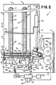
- Mixed mail feeder 1 separates individual mailpieces 3 from a stack of mixed mail generally designated at 5 and transports the individual mailpieces 3 to a subsequent mail processing station 7.
- Mail processing station 7 can be any one of a plurality of devices such as a meter for printing postage on the mailpiece 3, an OCR reader for reading addresses off of the mailpiece 3, a sorting device for sorting the individual mailpieces 3 to designated bins or areas, or even a scale that weighs the mailpiece.
- the key point is that the mixed mail feeder 1 functions to separate individual mailpieces 3 from a stack of mixed mail 5 and deliver the individual mailpieces 3 sequentially to the mail processing station 7.
- Mixed mail feeder 1 includes a table 9 upon which all of the components of the mixed mail feeder 1 are mounted. At an input end of the mixed mail feeder 1, generally designated by the arrow 11, the stack of mixed mail 5 is placed on edge by an operator in front of a guide wall 13. Guide wall 13 acts as a support against which the stack of mixed mail 5 rests. Moreover, guide wall 13 includes a cylindrical portion 13a which is mounted to slide on a guide rod 15 fixedly attached to platform 10 which is mounted to table 9.
- Platform 10 has first and second slots 17, 19, in a horizontal surface 21 thereof.
- the slots 17, 19 each permit a top portion of a respective individual continuous belt 23, 25 to project therethrough.
- Belts 23, 25 each have a plurality of individual track portions 27 over the full extent of the belts 23, 25.
- the bottom of guide wall 13 removably fits in adjacent track portions 27 of each of belts 23 and 25 so that guide wall 13 moves with belts 23, 25 in the direction of arrow A.
- the cylindrical portion 13a slides along guide rod 15 to keep the standing orientation of guide wall 13 in the position shown in Fig. 1.
- Continuous belts 23, 25 are mounted in a conventional manner around a pulley at each end (not shown).
- One pulley is an idler pulley while the other is driven by a motor 29.
- the motor 29 drives a common shaft (not shown) connected to the drive pulleys of each of the belts 23, 25 such that the belts 23, 25 will be driven at the same velocity to move around their respective idler and driven pulleys.
- the guide wall 13 moves therewith so that the entire stack of mixed mail 5 is moved toward a nudger wall 31.
- the stack of mixed mail 5 will have individual mailpieces 3 moved from the stack downstream so that the stack of mixed mailpieces is continuously reduced in size.
- the guide wall 13 can be lifted out of the individual tracks 27 of the belts 23, 25 by pulling the guide wall 13 up to rotate, via the cylindrical portion 13a, about the guide rod 15. Once the bottom of the guide wall 13 is clear of the individual tracks 27 of the belts 23, 25, it can be slid backward in the opposite direction from that of arrow A and placed in a desired position to receive additional mixed mail.
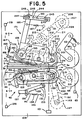
- nudger wall 31 includes a plurality of rollers 33 mounted therein in a conventional manner to be freely rotatable. Furthermore, nudger wall 31 has a cutout 35 in a lower corner thereof through which driven nudger rollers 37 project. Moreover, a plurality of roller bars 38 are rotatably mounted in a conventional manner in a slot 40 of platform 10.
- a continuous belt (not shown) is driven around the roller bars 38. The use of the continuous belt provides a greater coefficient of friction as compared to the roller bars and thus improves the feed force and provides for a simple drive structure.
- the nudger rollers 37 are mounted to be driven into rotation within a nudger arm 39.
- the four nudger rollers 37 are driven together by a motor 41, mounted on nudger arm 39, via a drive train 43 as shown schematically in Figure 2 and in detail in Figure 4.
- all of the nudger rollers 37 are driven into rotation in a clockwise direction. Accordingly, as the stack of mixed mail 5 is moved toward nudger wall 31, the lead mailpiece 3a is forced into contact with the nudger rollers 37.
- the force of the driven nudger rollers 37 acts against the lead mailpiece 3a to move the mailpiece 3a in the direction of a separator device 45, thereby shingling the lead mailpiece 3a from the stack of mixed mail 5 as shown in Figures 1 and 2.
- the shingled stack is then transported to the nip 46 of separator 45 which separates the lead mailpiece 3a from the shingled stack and delivers it to take-away rollers 65 which transport the individual lead mailpiece 3a further downstream to mail processing station 7.
- Motor 41 has a shaft 41a connected to a pulley 42.
- a continuous belt 44 is disposed around pulley 42 and a second pulley 46.
- Pulley 46 is fixedly mounted to a rotatable shaft 48 mounted in nudger arm 39.
- Fixedly mounted to shaft 48 is a third pulley 50.
- Additional shafts 52, 54 are also rotatably mounted in nudger arm 39 and respectively have fourth and fifth pulleys 56, 58 fixedly mounted thereto.
- Nudger rollers 37 are mounted on a corresponding one of shafts 52, 54. Accordingly, as motor 41 rotates pulley 42 in the clockwise direction of Fig.
- pulley 46 and hub 48 are drive in the clockwise direction as well. Since a continuous belt 60 passes around pulleys 48, 56, and 58, shafts 52, 54 are forced to rotate in the clockwise direction causing a corresponding rotational movement in all of nudger rollers 37.
- the normal force is created by a spring 49 that is fixedly mounted at one end to the nudger wall 31 and at its other end to a mounting platform 50 of nudger arm 39.
- the nudger arm 39 is pivotally mounted about a conventional pivot structure 51 so that the spring 49 biases the nudger rollers 37 through the cutout 35 and into contact with the lead mailpiece 3a.
- the nudger arm 39 is forced to rotate in the clockwise direction of Figure 2 around pivot structure 51 in opposition to the basing force of the spring 49.
- the spring 49 is extended due to the rotation of nudger arm 39 about the pivot structure 51, the force exerted by the spring 49 is continually increased.
- the thin and untabbed mailpieces are fed by the nudger rollers 37 into the separator 45, they can easily be buckled and damaged due to the feeding force of the nudger rollers 37 and the forces exerted by separator 45. Additionally, if the guide wall 13 is advanced too far toward the nudger wall 31 the stack of mixed mail 5 will be clamped in place preventing the feeding of individual mailpieces from stack 5. To prevent this from happening, the contact point of the nudger rollers 37 against the lead mailpiece 3a is always maintained closer to the stack 5 than the facing surface of the nudger wall 31 is to the stack 5.
- the normal force which is created by the positioning of the mailpiece stack 5 against the nudger rollers 37 and the corresponding force created by the extension of spring 49 needs to be maintained in an approximate range of 1-2 newtons in order to ensure that the various types of mixed mailpieces 3 which may be processed are properly shingled and fed vertically into the throat of separator 45 without being damaged or stalled at nudger wall 31.
- the normal force is provided by the extension of spring 49, it can be controlled by accurately regulating the position of nudger arm 39 which correspondingly regulates the extension of spring 49. That is, since the normal force applied by spring 49 is directly proportional to its extension, the normal force that it applies to the stack of mixed mail 5 is controlled by regulating the extension of spring 49.
- the aforementioned control of the extension of spring 49 and rotation of nudger arm 39 is accomplished via the utilization of conventional through-beam sensors 53, 55, and 57 and a finger 59 which projects from nudger arm 39.
- the finger 59 will move between the three sensors 53, 55 and 57.
- a signal is sent by the respective blocked through-beam sensor to a mixed mail feeder microprocessor 61 indicating the position of the finger 59 at the blocked sensor.
- the known position of the finger 59 corresponds to a known position of the nudger arm 39 and a known amount of extension of the spring 49.
- the microprocessor 61 If the finger 59 is blocking the beam of the first sensor 53, the microprocessor 61 knows that the nudger rollers 37 are at their innermost position relative to the stack of mixed mail 5. At this position, the normal force exerted by spring 49 is below the desired minimum value of I newton and must be increased. The increase in normal force is created when the microprocessor 61, in response to a signal from sensor 53, energizes the motor 29 to move the belts 23 and 25 such that the guide wall 13 advances the mixed mail stack 5 into the nudger rollers 37. The motor 29 will advance the stack of mixed mail 5 until the nudger arm 39 pivots about pivot structure 51 to the position where finger 59 blocks the through-beam sensor 55.
- the sensor 55 sends a signal to microprocessor 61 which in turn deenergizes motor 29 stopping the advance of the stack of mixed mail 5 toward the nudger rollers 37.
- the nudger rollers 37 are considered to be in the "out" position where the maximum desired normal force is being exerted on the lead mailpiece 3a due to the extension of the spring 49.
- the nudger rollers 37 gradually move toward the innermost normal force position.
- microprocessor 61 When the nudger arm 39 has rotated inwardly such that the nudger rollers 37 are in the innermost normal force position, microprocessor 61 receives a signal from sensor 53 and energizes motor 29 to advance the stack of mail 5 until the second sensor 55 is blocked by the finger 59. In this manner, constant regulation of the normal force in the predetermined range is maintained.
- the automatic control of the normal force would only use the sensors 53 and 55 to ensure that the normal force generated by the nudger rollers 37 stays within the predetermined desired normal force range.
- a second tier of additional stack force can be applied if it is determined that a mailpiece 3 has stalled at the nudger rollers 37 or at the separator 45. That is, it is possible, since the mixed mail feeder 1 is designed to handle many different types of mixed mail, that a very heavy piece of mail may have stalled (become stuck) at the nudger rollers 37 or separator 45.
- the mixed mail feeder 1 determines that a stall has occurred is by the use of a through-beam sensor 63, which is positioned proximate to the nip of takeaway rollers 65. Takeaway rollers 65, in a conventional manner, receive individual mailpieces from separator 45 and move the individual mailpieces 3 downstream.
- the takeaway rollers 65 feed a first mailpiece and do not process a second mailpiece 3 downstream in a predetermined period of time of, for example, 1,000 msec
- the through-beam of sensor 63 does not detect the lead edge of the second mailpiece during that same predetermined time period. If the microprocessor 61 does not receive an indication from the sensor 63 that a leading edge of the second mailpiece has passed thereby within the predetermine period of time, microprocessor 61 is programmed to assume that a stall has occurred somewhere upstream. Microprocessor 61 then energizes motor 29 to cause the stack of mixed mail 5 to be moved toward the nudger wall 31. The nudger arm 39 is forced rotate about the pivot point 51 and the spring 49 is further extended.
- nudger arm 39 is advanced to block the third sensor 57.
- a stalled normal force which is larger than the maximum normal force applied under normal operating conditions, is being exerted on the lead mailpiece 3a by the nudger rollers 37 and the motor 29 is rendered inoperative by microprocessor 61.
- the increased normal force can simply be due to the further extension of the spring 49 as the nudger arm 39 is rotated from its position blocking sensor 55 to its position blocking sensor 57, or can be further increased by the force of an additional compression spring 66 which only contacts the nudger arm 39 to provide an additional spring force thereto when the nudger arm 39 moves beyond the position from the blocking of sensor 55 toward the blocking of sensor 57.
- the takeaway sensor 63 will provide an input to the microprocessor 61 identifying that the lead edge of the stalled mailpiece has passed thereby and the processing of individual mailpieces 3 will continue by driving the nudger rollers 37 until the nudger arm 39 moves to a position where the first sensor 53 is blocked by finger 59. At this position, the system will operate as discussed above, regulating a force profile by maintaining the position of nudger arm 39 between the sensors 53 and 55.
- the microprocessor 61 In the event however, that even the additional normal force provided by the movement of the nudger arm 39 to block the sensor 57 does not correct the stalled problem, the microprocessor 61, after a predetermined period of time, will provide an input to the user via a display 67 identifying the stalled condition and advising that operator intervention is required to correct the problem.
- the microprocessor 61 controls all of the motors typically associated with the stack advance, shingling device, separator, and take away rollers and includes known clock structure for determining the predetermined time periods discussed above. Empirical testing has shown that for the anticipated mixed mailpiece profile the additional normal force applied during movement of finger 59 from sensor 55 to sensor 57 goes from 2 to 5 newtons.
- the spring 65 is selected and preloaded so that upon initial
- a different mechanism is used to provide additional force in the situation where stalled mail is detected. That is, once the microprocessor 61 determines that a stall has occurred, utilization of a solenoid 71 and another spring 73 provides additional normal force in an attempt to overcome the stalled situation.
- the solenoid 71 is fixedly mounted to the platform 9 and the spring 73 has one end fixedly mounted to the nudger arm 39 and a second end fixedly mounted to a moveable plunger 75 of solenoid 71.
- the spring 73 is slack, thereby providing no additional normal spring force.
- the microprocessor 61 energizes the solenoid 71 to withdraw the plunger 75 such that the spring 73 is extended to provide an additional normal force to the mixed mail stack 5 via the nudger rollers 37.
- the force applied by the solenoid/spring combination 71/73 can be consistently applied for a predetermined period of time or can be pulsed to help the stalled mail break away.
- different levels of force can be applied by the spring 73 and solenoid 71 combination over a predetermined time period in an attempt to break the stalled mailpiece away.
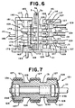
- separator 45 includes a reverse belt assembly 105 and a feed belt assembly 107.
- Feed belt assembly 107 is fixedly mounted to a feed deck 109.
- Shafts 111, 113, and 115 are fixedly mounted in feed deck 109 and end plate 117.
- Clips 119 retain shafts 111, 113 and 115 in end plate 117 while shaft 111 is mounted for rotation therein.
- Pulley assemblies 121, 123, and 125 are respectively mounted on shafts 111, 113, and 115 to be rotatable thereabout.
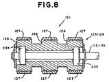
- Figures 7 and 8 respectively show the mounting structure of the driven pulley 121 and the idler pulleys 123/125.
- each of the idler pulley assemblies 123/125 is mounted on ball bearings 235 about their respective shafts 113/115.
- Driven pulley assembly 121 is also mounted on ball bearings 235 but is also mounted on an overrunning clutch 233 for purposes to be discussed later.
- Each pulley assembly 121/123/125 has three serrated, crowned hub portions 126 around which a respective one of each of three continuous belts 127 is disposed.
- a bracket 129 has a free end 131 at which a roller 133 is mounted for rotation and a second end 135 which is pivotably mounted to a bracket 137 which itself is fixedly mounted to feed deck 109.
- a spring 139 has a first end 141 connected to the second end 135 of bracket 129 and a second end 143 fixedly mounted within the mail handling machine. Spring 139 biases roller 133 into belt 127 to maintain a proper belt tension. As shown in Figure 6, there is a tension roller 133 for each belt 127.
- the feed belt assembly 107 is driven by a motor 147 which is controlled by microprocessor 61.
- a shaft 149 is driven by motor 147 and in turn drives a pulley 151 which is fixedly mounted to shaft 149.
- a continuous belt 153 is disposed around pulley 151 and also around a pulley 155 fixedly mounted to a lower portion of shaft 111 which extends below deck 109.
- pulley 151, pulley 155, shaft 111, and pulley assembly 121 also rotate in the clockwise direction.
- the clockwise rotation of pulley assembly 121 causes belts 127 to move in the clockwise direction with idler pulley assemblies 123/125, thereby feeding the lead mailpiece 3a toward the take away rollers 65.
- Feed belt assembly 107 also includes a guide 157 fixedly attached to feed deck 109.
- Guide 157 includes 4 fingers 159 which extend on either side of the three feed belts 127.
- the guide 157 prevents the mailpieces from hitting and getting caught on the three belts 127 and guides the mailpieces 3 toward separator nip 46. This prevents the mailpieces 3 from being routed behind feed belt apparatus 107.
- Reverse belt assembly 105 includes a mailpiece ingestion guide plate 163 that is pivotably mounted to feed deck 109 and biased toward mailpieces 3 by spring 165.
- Spring 165 is connected to a post 167 fixed to base 109.
- Ingestion guide 163 is mounted on and pivots about a shaft 169 which itself is fixedly mounted at one end in feed deck 109.
- Middle finger 176 prevents mail from curling up between the reverse belt assembly retard belts 175. It is important to note that the positioning of the biased ingestion guide 163 within nip 46 helps to solve two fundamental problems associated with the separation and feeding of mixed mail.
- a through-beam sensor 101 is located just upstream from nip 46. The sensor provides an indication to microprocessor 61 as to whether a mailpiece 3 is present.
- microprocessor 61 If no mailpiece is sensed as being present microprocessor 61 operates the nudger rollers 37 to continue feeding mailpieces 3 toward the nip 46. However, if sensor 101 senses the presence of a mailpiece 3, microprocessor 61 stops the feeding of mailpieces by nudger rollers 37. Since the mailpieces are only being acted upon by the separator 45 and not the nudger rollers 37, it is less likely that thin mailpieces will curl up in the nip. However when the nudger rollers 37 are stopped, the sensed mailpiece has not been fully ingested in nip 46 and it is possible that in some instances the feed belts 127 will not be able to move the lead mailpiece 3a into nip 46 such that a stall occurs.
- the biased ingestion guide 163 provides a normal force against the mailpiece 3a which increases the feed force of the feed belts 127 to help prevent the stalled mail situation.
- the ingestion guide 163 assists in the feeding of short mailpieces which leave the nudger rollers 37 before being fully ingested in to nip 46.
- the fingers 173, 176 were either covered with aluminum tape or made from aluminum or stainless steel which significantly reduced the number of stalls observed.
- the microprocessor assumes a stall has occurred upstream and causes the nudger rollers 37 to feed mailpieces toward nip 46 while concurrently increasing the normal stack force as described above in connection with take away sensor 63.
- Main bracket assembly 171 includes a top bracket portion 177 and a bottom bracket portion 179 which are interconnected via an intermediate bracket portion 181.
- Main bracket assembly 171 is mounted to be freely rotatably around a drive shaft 183.
- lever arm 185 is connected to a first spring 187 and a second spring 189.
- springs 187 and 189 are mounted to bias the main bracket assembly 171 toward the mailpieces 3 as will be discussed in more detail below.
- a pulley assembly 190 Fixedly mounted on shaft 183 is a pulley assembly 190 having two crowned hub portions (not shown but similar to the pulley/hub configuration of Figure 7 ) around which belts 175 are disposed. Also fixedly mounted on shaft 183 is a second pulley 193. Additionally, a second shaft 195 is fixedly mounted at each end in brackets 177 and 179 and has a pulley assembly (with two hub portions not shown) 197 mounted for rotation thereabout in the same manner as shown in Figure 8. Likewise, a third shaft 199 is also fixedly mounted between end brackets 177 and 179 and has a pulley assembly (with two hub portions not shown) 201 mounted for rotation thereabout in the same manner as shown in Figure 8.
- the two belts 175 are each disposed around a respective hub of each of the pulley assemblies 190, 197, 201. Additionally, a roller 178 is mounted for rotation on pulley 190. Roller 178 rides on the middle feed belt 127 when no mail is present.
- shaft 183 is driven into rotation in the clockwise direction of Figure 5 causing the pulley assembly 190 to rotate therewith which in turn causes the belts 175 to move around the idler pulley assemblies 197 and 201.
- feed belts 127 drive the lead mailpiece 3a toward the take away rollers 65 while the opposite rotation of the reverse belt assembly belts 175 separate the second mailpiece 3b from the lead mailpiece 3a so that only a single mailpiece 3a is removed by the take away rollers 65 and processed further downstream. That is, the feeding force of the feed belts 127 is greater than the reverse drive force of the reverse belts 175 which is greater than the inter-document forces.
- the force of the feed belts 127 and the reverse belts 175 overcome the inter-document forces to shear the mailpieces away from each other.
- Drive shaft 183 is driven into rotation as follows.
- a motor 205 is fixedly mounted below feed deck 109.
- Motor 205 drives a shaft 207 into clockwise rotation which causes a pulley 209 attached to the shaft 207 to rotate in that same direction.
- a continuous belt 211 is disposed around pulley 209 and another pulley 212.
- Pulley 212 is fixedly connected to a shaft 213 upon which another pulley 215 is fixedly connected.
- a second continuous belt 217 is disposed around pulley 215, pulley 193 and a pulley 219 associated with take away rollers 65.
- the motor 205 which is controlled by microprocessor 61 not only drives the shaft 183 in the clockwise direction but at the same time the shaft 221 around which the take away roller pulley 219 is mounted is driven in the clockwise direction.
- a single motor 205 drives the retard assembly belts 175 to separate the mailpieces as well as the take away rollers 65 for accelerating and feeding the lead mailpiece 3a downstream.
- the feed assembly belts 127 are driven by a separate motor 147.
- the reason for driving the feed belt assembly 107 with a different motor than both the reverse belt assembly 105 and the take away rollers 65 is to prevent a problem which can occur in known singulating apparatus where the take away rollers, the reverse belt assembly, and the feed belt assembly are all driven by a single motor. That is, in the situation where a single motor is used the entire singulating assembly may fail to separate the second mailpiece 3b from the lead the mailpiece 3a such that two mailpieces in overlapping relationship to each other (known as a "double") are passed out of the singulator assembly and fed into the take away rollers 65. In this situation it is often the case that the take away rollers may continue to feed the double mailpiece structure.
- the singulating apparatus Since the purpose of the singulating apparatus is to ensure that only individual pieces of mail are processed downstream, this is an undesirable situation.
- the microprocessor 61 will stop the motor 147 from driving the feed belt assembly belts 127.
- the take away roller 65 will pull the lead mailpiece 3a while the belts 175 of the reverse belt assembly 105 are still driven to separate the second mailpiece 3b away from the lead mailpiece 3a.
- the capability of the singulating apparatus to ensure that doubles are not feed to the take away roller 65 is effectively enhanced.
- the feed roller belts 127 are once again driven to separate the next mailpiece (in this case 3b) from the shingled stack of mail.
- Figure 7 shows that pulley assembly 121 is mounted on drive shaft 111 via a needle bearing clutch 233. Moreover, the pulley assembly 121 is also mounted on ball bearings 235.
- the needle bearing clutch 233 engages the pulley assembly 121 and drives it into rotation therewith causing the feed belts 127 to move in a corresponding manner.
- the nature of the needle bearing clutch allows the pulley assembly 121 to spin freely about the ball bearings 235.
- clutch 233 minimizes sliding contact between the feed belts 127 and the mailpieces thereby reducing wear on the feed belts 127.
- the use of the two basing springs 187, 189 provides an apparatus for automatically causing the reverse belt assembly 105 to exert a light nip force (preferably in a range of approximately 3-3.5 newtons) on the mailpieces passing thereby when the mailpiece is thin (a thickness less than approximately 5 millimeters.
- a nip force approximately greater than 10 newtons is applied.
- the reason for this two stage force profile is that if the higher normal forces are exerted on the thin mailpieces they have a tendency to buckle in the nip 46 and become damaged. This is particularly true for untabbed mailpieces.
- FIG. 5 provides the two stage force profile as follows.
- Spring 187 is fixedly mounted at one end to arm 185 and at a second end to a post 241 fixedly connected to feed deck 109.
- Spring 187 is always in tension to bias the reverse belts 175 into contact with the mailpieces 3.
- bracket 171 is forced to rotate in the counterclockwise direction about shaft 183 extending the spring 187 further such that the biasing force increases but remains below 5 newtons.
- bracket 171 When a mailpiece of approximately 5 millimeters is in nip 46 however, bracket 171 is rotated to a point where spring 189 provides an additional biasing force in addition to that of spring 187 such that the combined basing force of springs 187/189 is approximately 10 newtons. That is, spring 189 is fixedly connected at one end to a post 243 fixedly connected to deck 109. The other end of spring 189 is connected to a post 244 extending from a plate 245 mounted for slideable movement on post 243 and another post 246 fixedly connected to arm 185. Plate 245 has first and second slots 247, 249 through which respective posts 246 and 243 extend.
- spring 189 When mailpieces less than 5 millimeters thick are in nip 46 spring 189 is preloaded at a force of approximately 6 newtons such that it pulls plate 245 via post 243 such that the left edge of slot 247 abuts against post 246. In this position, post 244 is free to float in slot 248 such that the preloaded force of spring 189 is not applied to arm 185. However, when a mailpiece thicker than 5 millimeters enters nip 46, arm 185 rotates until post 244 contacts the left edge of slot 248 at which point the preloaded force of spring 189 is immediately applied to arm 185 increasing the total basing force from approximately 3,5 newtons to approximately 10 newtons.
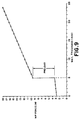
- Figure 9 shows the preferred force profile resulting from springs 187/189 as a function of mailpiece thickness.
- the large step up in the force curve shows that at 5 millimeters the preloaded spring 189 is applied.
- Sensor 250 can be used in lieu of sensor 63 to detect the trail edge of a mailpiece leaving separator 45 to identify when to restart feed belts 127 and sensor 251 will cause the nudger rollers to be driven if it does not detect the presence of mailpieces.
Landscapes
- Engineering & Computer Science (AREA)
- Mechanical Engineering (AREA)
- Sheets, Magazines, And Separation Thereof (AREA)
- Sorting Of Articles (AREA)
- Controlling Sheets Or Webs (AREA)
Applications Claiming Priority (2)
| Application Number | Priority Date | Filing Date | Title |
|---|---|---|---|
| US08/943,407 US6003857A (en) | 1997-10-03 | 1997-10-03 | Singulating apparatus for a mail handling system |
| US943407 | 1997-10-03 |
Publications (3)
| Publication Number | Publication Date |
|---|---|
| EP0906881A1 true EP0906881A1 (de) | 1999-04-07 |
| EP0906881B1 EP0906881B1 (de) | 2002-09-04 |
| EP0906881B2 EP0906881B2 (de) | 2006-08-23 |
Family
ID=25479608
Family Applications (1)
| Application Number | Title | Priority Date | Filing Date |
|---|---|---|---|
| EP98118650A Expired - Lifetime EP0906881B2 (de) | 1997-10-03 | 1998-10-02 | Vereinzelungsgerät für ein Posthandhabungssystem |
Country Status (4)
| Country | Link |
|---|---|
| US (1) | US6003857A (de) |
| EP (1) | EP0906881B2 (de) |
| CA (1) | CA2249284C (de) |
| DE (1) | DE69807616T3 (de) |
Cited By (5)
| Publication number | Priority date | Publication date | Assignee | Title |
|---|---|---|---|---|
| US6354583B1 (en) | 1999-01-25 | 2002-03-12 | Bell & Howell Mail And Messaging Technologies Company | Sheet feeder apparatus and method with throughput control |
| EP1332891A1 (de) * | 2002-02-01 | 2003-08-06 | Pitney Bowes Deutschland GmbH | Postbearbeitungssystem |
| EP2199237A1 (de) * | 2008-12-19 | 2010-06-23 | Neopost Technologies | Perfektionierte Einspeisevorrichtung für Postartikel |
| EP2289827A3 (de) * | 2009-08-27 | 2013-04-17 | Siemens Aktiengesellschaft | Vorrichtung und Verfahren zum Vereinzeln von flachen Gegenständen mit Kompensation der Abnutzung |
| US10017341B2 (en) | 2015-05-22 | 2018-07-10 | Giesecke+Devrient Currency Technology Gmbh | Device for processing sheet material |
Families Citing this family (35)
| Publication number | Priority date | Publication date | Assignee | Title |
|---|---|---|---|---|
| US6276679B1 (en) * | 1999-11-23 | 2001-08-21 | Pitney Bowes Inc. | Floating idler pulley retard system for mixed mail separation |
| JP3372925B2 (ja) * | 2000-03-21 | 2003-02-04 | 日本電気株式会社 | 郵便情報入力装置とそのデータの表示方法 |
| US6897394B1 (en) * | 2000-04-04 | 2005-05-24 | Opex Corporation | System and method for automated document processing |
| ATE367341T1 (de) | 2000-04-28 | 2007-08-15 | Siemens Ag | Intelligente vereinzelungsförderanlage mit selektivem votrieb |
| US6585251B2 (en) | 2001-11-13 | 2003-07-01 | Pitney Bowes Inc. | Articulating separator |
| US6988021B2 (en) | 2001-12-19 | 2006-01-17 | Pitney Bowes Inc. | Method of addressing and sorting an interoffice distribution using an incoming mail sorting apparatus |
| FR2833934B1 (fr) * | 2001-12-24 | 2004-07-09 | Neopost Ind | Dispositif selecteur d'articles de courrier |
| US7071437B2 (en) | 2001-12-31 | 2006-07-04 | Pitney Bowes Inc. | System for detecting the presence of harmful materials in an incoming mail stream |
| US6740836B2 (en) | 2001-12-31 | 2004-05-25 | Pitney Bowes Inc. | System and method for outsorting suspect mail from an incoming mail stream |
| US6905661B2 (en) | 2001-12-31 | 2005-06-14 | Pitney Bowes Inc. | System for sanitizing and sorting mail |
| US20030124039A1 (en) * | 2001-12-31 | 2003-07-03 | Ryan William E. | System for sanitizing incoming mail |
| US7165053B2 (en) * | 2002-06-13 | 2007-01-16 | Pitney Bowes Inc. | System and method for pre-feeding mailpieces, detecting the presence of harmful materials in the mailpieces and sorting the mailpieces |
| US6886419B2 (en) * | 2002-06-20 | 2005-05-03 | Pitney Bowes Inc. | Mail piece for obtaining samples of harmful materials in mail processing equipment |
| US6781078B2 (en) | 2002-06-28 | 2004-08-24 | Pitney Bowes Inc. | System and method for identifying potentially life harming mailpieces in an incoming mail stream |
| EP1556297B1 (de) * | 2002-10-29 | 2008-04-23 | Siemens Aktiengesellschaft | Fördereinrichtung mit handhabung der verteilten artikel |
| DE10350623B3 (de) * | 2003-10-30 | 2005-04-14 | Siemens Ag | Vorrichtung zum Vereinzeln von flachen Sendungen in stehender Position aus einem Sendungsstapel |
| US7303188B2 (en) * | 2003-11-06 | 2007-12-04 | James Malatesta | Document separator |
| DE10356364B4 (de) * | 2003-11-28 | 2010-04-15 | Deutsche Post Ag | Stoffeingabe-Vorrichtung zur Weiterbeförderung von Postsendungen |
| DE102004037420B3 (de) * | 2004-07-30 | 2005-12-15 | Siemens Ag | Vorrichtung zum Herausziehen einzelner flacher Sendungen aus einer Vereinzelungsstrecke |
| DE102005012029B3 (de) * | 2005-03-16 | 2006-07-13 | Siemens Ag | Vorrichtung zum Vereinzeln von überlappenden flachen Sendungen |
| FR2906235B1 (fr) * | 2006-09-21 | 2009-05-29 | Solystic Sas | Dispositif de depilage d'envois postaux avec une gestion optimisee des conditions de depilage |
| US7806398B2 (en) * | 2007-10-03 | 2010-10-05 | Pitney Bowes Inc. | Ingestion guide assembly for augmenting sheet material separation in a singulating apparatus |
| US7934719B2 (en) * | 2007-12-05 | 2011-05-03 | Burroughs Payment Systems, Inc. | Document feeder flag assembly |
| US8016282B2 (en) * | 2007-12-21 | 2011-09-13 | Pitney Bowes Inc. | Transport for singulating items |
| JP2010208800A (ja) * | 2009-03-10 | 2010-09-24 | Toshiba Corp | 給紙装置 |
| JP5578878B2 (ja) * | 2010-02-24 | 2014-08-27 | キヤノン株式会社 | 給紙分離装置および記録装置 |
| FR2957906B1 (fr) * | 2010-03-25 | 2012-05-18 | Solystic | Dispositif d'alimentation pour envois postaux avec un magasin et un depileur separes |
| US9079730B2 (en) | 2010-04-19 | 2015-07-14 | Opex Corporation | Feeder for feeding document to document imaging system and method for feeding documents |
| JP2014141341A (ja) * | 2013-01-25 | 2014-08-07 | Riso Kagaku Corp | 印刷装置 |
| US9061849B2 (en) | 2013-03-14 | 2015-06-23 | United States Postal Service | System and method of article feeder operation |
| US9056738B2 (en) | 2013-03-13 | 2015-06-16 | United States Postal Service | Anti-rotation device and method of use |
| US9340377B2 (en) | 2013-03-12 | 2016-05-17 | United States Postal Service | System and method of automatic feeder stack management |
| US9376275B2 (en) | 2013-03-12 | 2016-06-28 | United States Postal Service | Article feeder with a retractable product guide |
| US9044783B2 (en) | 2013-03-12 | 2015-06-02 | The United States Postal Service | System and method of unloading a container of items |
| US10472191B2 (en) * | 2016-07-28 | 2019-11-12 | Ncr Corporation | Adaptive pressure media feeding |
Citations (3)
| Publication number | Priority date | Publication date | Assignee | Title |
|---|---|---|---|---|
| US4909499A (en) * | 1988-12-28 | 1990-03-20 | Pitney Bowes Inc. | Mail singulating apparatus |
| US5074540A (en) * | 1990-11-05 | 1991-12-24 | Pitney Bowes Inc. | Document singulating apparatus |
| US5431385A (en) * | 1994-03-03 | 1995-07-11 | Pitney Bowes Inc. | Ingestion roller for mixed mail feeder |
Family Cites Families (7)
| Publication number | Priority date | Publication date | Assignee | Title |
|---|---|---|---|---|
| US3988017A (en) † | 1975-03-20 | 1976-10-26 | Lockheed Electronics Co., Inc. | Workpiece feeding device |
| US4030722A (en) † | 1975-05-13 | 1977-06-21 | Pitney-Bowes, Inc. | Sheet-material separator and feeder system |
| US4893804A (en) * | 1987-07-01 | 1990-01-16 | Nec Corporation | Apparatus for feeding sheet articles |
| DE3833506A1 (de) * | 1988-10-01 | 1990-04-05 | Didier Werke Ag | Vorrichtung zum aufspritzen einer ausbesserungsmasse auf einen lochstein |
| US4978114A (en) * | 1989-11-14 | 1990-12-18 | Pitney Bowes Inc. | Reverse belt singulating apparatus |
| US5238236A (en) * | 1992-11-12 | 1993-08-24 | Pitney Bowes Inc. | Document singulating apparatus for feeding upright documents of varying thickness |
| JP3205624B2 (ja) * | 1992-12-28 | 2001-09-04 | キヤノン株式会社 | 給紙装置 |
-
1997
- 1997-10-03 US US08/943,407 patent/US6003857A/en not_active Expired - Lifetime
-
1998
- 1998-10-01 CA CA002249284A patent/CA2249284C/en not_active Expired - Fee Related
- 1998-10-02 EP EP98118650A patent/EP0906881B2/de not_active Expired - Lifetime
- 1998-10-02 DE DE69807616T patent/DE69807616T3/de not_active Expired - Lifetime
Patent Citations (3)
| Publication number | Priority date | Publication date | Assignee | Title |
|---|---|---|---|---|
| US4909499A (en) * | 1988-12-28 | 1990-03-20 | Pitney Bowes Inc. | Mail singulating apparatus |
| US5074540A (en) * | 1990-11-05 | 1991-12-24 | Pitney Bowes Inc. | Document singulating apparatus |
| US5431385A (en) * | 1994-03-03 | 1995-07-11 | Pitney Bowes Inc. | Ingestion roller for mixed mail feeder |
Cited By (7)
| Publication number | Priority date | Publication date | Assignee | Title |
|---|---|---|---|---|
| US6354583B1 (en) | 1999-01-25 | 2002-03-12 | Bell & Howell Mail And Messaging Technologies Company | Sheet feeder apparatus and method with throughput control |
| EP1332891A1 (de) * | 2002-02-01 | 2003-08-06 | Pitney Bowes Deutschland GmbH | Postbearbeitungssystem |
| EP2199237A1 (de) * | 2008-12-19 | 2010-06-23 | Neopost Technologies | Perfektionierte Einspeisevorrichtung für Postartikel |
| FR2940259A1 (fr) * | 2008-12-19 | 2010-06-25 | Neopost Technologies | Dispositif perfectionne d'alimentation en articles de courrier |
| US8083229B2 (en) | 2008-12-19 | 2011-12-27 | Neopost Technologies | Mailpiece feed device |
| EP2289827A3 (de) * | 2009-08-27 | 2013-04-17 | Siemens Aktiengesellschaft | Vorrichtung und Verfahren zum Vereinzeln von flachen Gegenständen mit Kompensation der Abnutzung |
| US10017341B2 (en) | 2015-05-22 | 2018-07-10 | Giesecke+Devrient Currency Technology Gmbh | Device for processing sheet material |
Also Published As
| Publication number | Publication date |
|---|---|
| CA2249284C (en) | 2002-09-03 |
| DE69807616D1 (de) | 2002-10-10 |
| CA2249284A1 (en) | 1999-04-03 |
| EP0906881B1 (de) | 2002-09-04 |
| US6003857A (en) | 1999-12-21 |
| DE69807616T2 (de) | 2003-08-07 |
| EP0906881B2 (de) | 2006-08-23 |
| DE69807616T3 (de) | 2007-03-08 |
Similar Documents
| Publication | Publication Date | Title |
|---|---|---|
| EP0906881B1 (de) | Vereinzelungsgerät für ein Posthandhabungssystem | |
| US5971391A (en) | Nudger for a mail handling system | |
| US6270070B1 (en) | Apparatus and method for detecting and correcting high stack forces | |
| US6217020B1 (en) | Method and apparatus for detecting proper mailpiece position for feeding | |
| EP0926085B1 (de) | Doppeltes Gerät zur Vereinzelung von Dokumenten für ein Postbearbeitungssystem | |
| US6435498B1 (en) | Aligner mechanism for a mail handling system | |
| US20020140156A1 (en) | Apparatus and method for controlling a document-handling machine | |
| US7168700B2 (en) | Sheet feeder apparatus and method with throughput control | |
| US5074540A (en) | Document singulating apparatus | |
| US5415068A (en) | Multi-function envelope feeder | |
| US6065748A (en) | Sheet stacking | |
| EP0660797A1 (de) | Vorrichtung zum überlappten abziehen von flachen gegenständen mit einer vor-fördereinrichtung. | |
| US4968419A (en) | Document processing system | |
| US5257777A (en) | Belt separator for document singulation | |
| US5456457A (en) | High speed separator with movable hold back belt for high speed flats feeder | |
| US5409204A (en) | Singulator assembly having a buffer with a biased arm | |
| US4548393A (en) | Inserter feeder document stop | |
| EP0881178A1 (de) | Blattzuführgerät | |
| US20010035602A1 (en) | Mail piece feeder for vertically orientated mail pieces and having reversible retard rollers | |
| AU639932B2 (en) | Single sheet picking and transport mechanism | |
| EP0852563B1 (de) | Trennvorrichtung mit Zurückhalteriemen für Zuführer | |
| JPH0117977B2 (de) | ||
| JPH05266316A (ja) | カード類の重送検知装置 | |
| JPH05262443A (ja) | カード類の重送検知装置 | |
| JPH05178471A (ja) | 給紙装置 |
Legal Events
| Date | Code | Title | Description |
|---|---|---|---|
| PUAI | Public reference made under article 153(3) epc to a published international application that has entered the european phase |
Free format text: ORIGINAL CODE: 0009012 |
|
| AK | Designated contracting states |
Kind code of ref document: A1 Designated state(s): DE FR GB |
|
| AX | Request for extension of the european patent |
Free format text: AL;LT;LV;MK;RO;SI |
|
| 17P | Request for examination filed |
Effective date: 19990715 |
|
| AKX | Designation fees paid |
Free format text: DE FR GB |
|
| 17Q | First examination report despatched |
Effective date: 20010209 |
|
| GRAG | Despatch of communication of intention to grant |
Free format text: ORIGINAL CODE: EPIDOS AGRA |
|
| GRAG | Despatch of communication of intention to grant |
Free format text: ORIGINAL CODE: EPIDOS AGRA |
|
| GRAH | Despatch of communication of intention to grant a patent |
Free format text: ORIGINAL CODE: EPIDOS IGRA |
|
| GRAH | Despatch of communication of intention to grant a patent |
Free format text: ORIGINAL CODE: EPIDOS IGRA |
|
| GRAA | (expected) grant |
Free format text: ORIGINAL CODE: 0009210 |
|
| AK | Designated contracting states |
Kind code of ref document: B1 Designated state(s): DE FR GB |
|
| REG | Reference to a national code |
Ref country code: GB Ref legal event code: FG4D |
|
| REF | Corresponds to: |
Ref document number: 69807616 Country of ref document: DE Date of ref document: 20021010 |
|
| ET | Fr: translation filed | ||
| PLBQ | Unpublished change to opponent data |
Free format text: ORIGINAL CODE: EPIDOS OPPO |
|
| PLBI | Opposition filed |
Free format text: ORIGINAL CODE: 0009260 |
|
| PLAX | Notice of opposition and request to file observation + time limit sent |
Free format text: ORIGINAL CODE: EPIDOSNOBS2 |
|
| 26 | Opposition filed |
Opponent name: FRANCOTYP-POSTALIA AKTIENGESELLSCHAFT & CO. KG Effective date: 20030523 |
|
| PLAX | Notice of opposition and request to file observation + time limit sent |
Free format text: ORIGINAL CODE: EPIDOSNOBS2 |
|
| PLBB | Reply of patent proprietor to notice(s) of opposition received |
Free format text: ORIGINAL CODE: EPIDOSNOBS3 |
|
| PLCK | Communication despatched that opposition was rejected |
Free format text: ORIGINAL CODE: EPIDOSNREJ1 |
|
| APBP | Date of receipt of notice of appeal recorded |
Free format text: ORIGINAL CODE: EPIDOSNNOA2O |
|
| APBQ | Date of receipt of statement of grounds of appeal recorded |
Free format text: ORIGINAL CODE: EPIDOSNNOA3O |
|
| PLAQ | Examination of admissibility of opposition: information related to despatch of communication + time limit deleted |
Free format text: ORIGINAL CODE: EPIDOSDOPE2 |
|
| PLAR | Examination of admissibility of opposition: information related to receipt of reply deleted |
Free format text: ORIGINAL CODE: EPIDOSDOPE4 |
|
| PLBQ | Unpublished change to opponent data |
Free format text: ORIGINAL CODE: EPIDOS OPPO |
|
| PLAB | Opposition data, opponent's data or that of the opponent's representative modified |
Free format text: ORIGINAL CODE: 0009299OPPO |
|
| R26 | Opposition filed (corrected) |
Opponent name: FRANCOTYP-POSTALIA AKTIENGESELLSCHAFT & CO. KG Effective date: 20030523 |
|
| APAH | Appeal reference modified |
Free format text: ORIGINAL CODE: EPIDOSCREFNO |
|
| APBU | Appeal procedure closed |
Free format text: ORIGINAL CODE: EPIDOSNNOA9O |
|
| PUAH | Patent maintained in amended form |
Free format text: ORIGINAL CODE: 0009272 |
|
| STAA | Information on the status of an ep patent application or granted ep patent |
Free format text: STATUS: PATENT MAINTAINED AS AMENDED |
|
| 27A | Patent maintained in amended form |
Effective date: 20060823 |
|
| AK | Designated contracting states |
Kind code of ref document: B2 Designated state(s): DE FR GB |
|
| ET3 | Fr: translation filed ** decision concerning opposition | ||
| PGFP | Annual fee paid to national office [announced via postgrant information from national office to epo] |
Ref country code: DE Payment date: 20091028 Year of fee payment: 12 |
|
| REG | Reference to a national code |
Ref country code: DE Ref legal event code: R119 Ref document number: 69807616 Country of ref document: DE Effective date: 20110502 |
|
| PGFP | Annual fee paid to national office [announced via postgrant information from national office to epo] |
Ref country code: FR Payment date: 20111028 Year of fee payment: 14 |
|
| PG25 | Lapsed in a contracting state [announced via postgrant information from national office to epo] |
Ref country code: DE Free format text: LAPSE BECAUSE OF NON-PAYMENT OF DUE FEES Effective date: 20110502 |
|
| REG | Reference to a national code |
Ref country code: FR Ref legal event code: ST Effective date: 20130628 |
|
| PG25 | Lapsed in a contracting state [announced via postgrant information from national office to epo] |
Ref country code: FR Free format text: LAPSE BECAUSE OF NON-PAYMENT OF DUE FEES Effective date: 20121031 |
|
| PGFP | Annual fee paid to national office [announced via postgrant information from national office to epo] |
Ref country code: GB Payment date: 20161027 Year of fee payment: 19 |
|
| GBPC | Gb: european patent ceased through non-payment of renewal fee |
Effective date: 20171002 |
|
| PG25 | Lapsed in a contracting state [announced via postgrant information from national office to epo] |
Ref country code: GB Free format text: LAPSE BECAUSE OF NON-PAYMENT OF DUE FEES Effective date: 20171002 |