EP0906814B2 - Razor with in situ sensor - Google Patents
Razor with in situ sensor Download PDFInfo
- Publication number
- EP0906814B2 EP0906814B2 EP98307575A EP98307575A EP0906814B2 EP 0906814 B2 EP0906814 B2 EP 0906814B2 EP 98307575 A EP98307575 A EP 98307575A EP 98307575 A EP98307575 A EP 98307575A EP 0906814 B2 EP0906814 B2 EP 0906814B2
- Authority
- EP
- European Patent Office
- Prior art keywords
- razor
- blades
- signal
- situ
- situ sensors
- Prior art date
- Legal status (The legal status is an assumption and is not a legal conclusion. Google has not performed a legal analysis and makes no representation as to the accuracy of the status listed.)
- Expired - Lifetime
Links
- 238000011065 in-situ storage Methods 0.000 title claims description 43
- 238000012545 processing Methods 0.000 claims description 16
- 230000004044 response Effects 0.000 claims description 16
- 239000000463 material Substances 0.000 claims description 8
- 239000002033 PVDF binder Substances 0.000 claims description 7
- 229920002981 polyvinylidene fluoride Polymers 0.000 claims description 7
- 229920006254 polymer film Polymers 0.000 claims description 3
- 125000006850 spacer group Chemical class 0.000 claims description 3
- 239000004020 conductor Substances 0.000 description 9
- 230000008859 change Effects 0.000 description 6
- 230000000007 visual effect Effects 0.000 description 4
- 210000004209 hair Anatomy 0.000 description 3
- 229920000642 polymer Polymers 0.000 description 2
- 239000007787 solid Substances 0.000 description 2
- 238000013519 translation Methods 0.000 description 2
- RYGMFSIKBFXOCR-UHFFFAOYSA-N Copper Chemical compound [Cu] RYGMFSIKBFXOCR-UHFFFAOYSA-N 0.000 description 1
- 230000009471 action Effects 0.000 description 1
- 230000008901 benefit Effects 0.000 description 1
- 230000001680 brushing effect Effects 0.000 description 1
- 239000002131 composite material Substances 0.000 description 1
- 230000008878 coupling Effects 0.000 description 1
- 238000010168 coupling process Methods 0.000 description 1
- 238000005859 coupling reaction Methods 0.000 description 1
- 230000001419 dependent effect Effects 0.000 description 1
- 238000001514 detection method Methods 0.000 description 1
- 238000000034 method Methods 0.000 description 1
- 238000012986 modification Methods 0.000 description 1
- 230000004048 modification Effects 0.000 description 1
- 230000008569 process Effects 0.000 description 1
- 239000008257 shaving cream Substances 0.000 description 1
- 239000000344 soap Substances 0.000 description 1
- 238000012546 transfer Methods 0.000 description 1
- XLYOFNOQVPJJNP-UHFFFAOYSA-N water Substances O XLYOFNOQVPJJNP-UHFFFAOYSA-N 0.000 description 1
Images


Classifications
-
- B—PERFORMING OPERATIONS; TRANSPORTING
- B26—HAND CUTTING TOOLS; CUTTING; SEVERING
- B26B—HAND-HELD CUTTING TOOLS NOT OTHERWISE PROVIDED FOR
- B26B21/00—Razors of the open or knife type; Safety razors or other shaving implements of the planing type; Hair-trimming devices involving a razor-blade; Equipment therefor
- B26B21/40—Details or accessories
- B26B21/4081—Shaving methods; Usage or wear indication; Testing methods
- B26B21/4087—Usage or wear indication
-
- B—PERFORMING OPERATIONS; TRANSPORTING
- B26—HAND CUTTING TOOLS; CUTTING; SEVERING
- B26B—HAND-HELD CUTTING TOOLS NOT OTHERWISE PROVIDED FOR
- B26B21/00—Razors of the open or knife type; Safety razors or other shaving implements of the planing type; Hair-trimming devices involving a razor-blade; Equipment therefor
- B26B21/40—Details or accessories
- B26B21/405—Electric features; Charging; Computing devices
- B26B21/4056—Sensors or controlling means
Definitions
- This invention relates to the placement of one or more in situ sensors in razor heads, to produce a movement or indication to aid in the quality of the shave.
- the invention relates to a razor having an in situ sensor.
- Efforts to improve shave quality have been on-going for many years. Much of the effort to improve shave quality has been directed toward making razor cartridges and blades more responsive to the various forces encountered by the razor during shaving. Examples of the results include razor systems having movable components, such as blades, cartridges which flex or bend in response to shaving forces and blades which move inward and outward in response to those forces.
- One common thread between all previous shaving systems with movable components is that the movements are produced by the function of a mechanical element, such as a spring or pivot. Consequently, one limitation on the function of all of these prior razor systems is that they are only as sensitive as their mechanical elements.
- US-A-5165170 discloses a razor including an integral hair detection means that provides real-time feedback, during shaving, of areas of beard remaining to be shaved.
- the razor comprises a razor assembly mounted on a handle for brushing against the surface of a person's face and vibrating in response to contact with hairs thereon; a pickup coupled to the handle responsive to the vibrations produced therein for generating a corresponding signal; and audio frequency amplifying means within the handle for amplifying the signal from the pickup as an audio frequency output.
- the present invention is directed to a wet shave shaving system which contains an in situ sensor within the razor cartridge.
- the sensor consists of a piezoelectric material which produces an electrical signal when it is strained.
- an active feedback system the signal would be transferred from the cartridge to the razor handle where an electronically-activated actuator would extend or retract as necessary to position the blades to produce a shave with a constant shave force.
- an electronically-activated element such as an indicator light
- the signal would provide an indication to the user that the blades are worn and should be replaced.
- wet shave razors are defined to be razors which are customarily utilized in conjunction with soap or shaving cream and hot water.
- the definition of wet shave razors includes both disposable razors, in which the user discards the entire unit after a certain number of uses, and permanent systems, with which the user discards and replaces the razor cartridge after a certain number of uses.
- the razor head, or cartridge is the portion which surrounds and contains the blade or blades.
- the combination of the razor head and the handle, either permanent or disposable, is defined as the razor system.
- the present invention provides for a wet shave razor head having one or more in situ sensors which receive and produce a response to the forces encountered by the razor head during shaving.
- the sensors are constructed from a piezoelectric material which produces an electrical signal when it is strained.
- a preferred piezoelectric polymer is polyvinylidene fluoride (PVDF) of the type sold by Amp Inc., Valley Forge, Pennsylvania. PVDF is especially preferred as a sensor because it is very flexible and provides a good, strong electrical signal.
- PVDF is commercially available in forms of various thickness which facilitates the processing of the material into a sensor which may be placed in virtually any location in a razor system.
- the piezoelectric polymer sensor is a film which is applied directly to or close to the blades within the razor head.
- FIGS 1 and 2 illustrate cartridge 10 having two blades, 11, 12.
- the in situ sensor in the form of a piezoelectric polymer film 14, 15, is coated on a portion of blades 11, 12 such that the film will be in a position to detect the result of the forces encountered during shaving and to provide an electrical signal based on those forces.
- the various forces which normally will be encountered are those which flex the cartridge upward or downward and those which produce stress and strain on the blade or blades.
- Means for transmitting the electrical signal from the in situ sensor to the receptor are also provided within the razor head.
- such transmitting means comprise a conductive material, such as wire 18, which receives the electrical signal or signals from the sensor or sensors and then transmits the signals through the razor head to one or more receptors, which are preferably located within the razor handle.
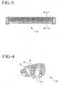
- the in situ sensor is in the form of a solid piece of a piezoelectric material 23, preferably PVDF or a composite thereof, which is located between the two blades 21, 22.
- the sensor acts as a spacer to hold the two blades away from each other and at the same time detects the result of forces encountered during shaving.
- the location of the sensor in this embodiment is particularly useful for detecting forces acting on the razor head.
- the sensor generates an electrical signal from the forces transmitted through transmitting means 24 to one or more receptors which are preferably located within the razor handle.
- the senor may be positioned within the razor handle.
- the sensor would indirectly measure the forces on the blade or blades which are transferred to the handle.
- a preferred embodiment of this alternative illustrated in Figure 4A employs a piezoresistive or piezoelectric sensor 51 which is placed in the handle 30.
- a movable piston 50 is placed in contact with the razor cartridge 52 or blades and translates the forces encountered during shaving to the sensor.
- FIG. 5 illustrates the razor handle 30 of the present invention.
- the handle in this case illustrated as a permanent system with a replaceable cartridge, comprises attachment means 32 for the attachment of the razor cartridge, piston 31, conductor 34 and a receptor which is illustrated in Figure 5 in the form of electric motor 38.
- conductor 34 is connected to the transmitting means of the razor head to form a circuit and receive the in situ sensor signal through the transmitting means.
- the transmitting means of the razor head and the conductor may be a single unit.
- the connection is accomplished by placing connectors on the exposed ends of the transmitting means and the conductor so that they attach to each other upon the placement of a razor head on the handle.
- the conductor may be constructed from any suitable conductive material, such as copper wire.
- the first receptor embodiment is an active system in which the receptor is in the form of a simple signal processing circuit which processes the in situ sensor signal and produces a response to move and position the blades.
- the receptor is a signal processing circuit in conjunction with an actuator which is used to move and position the piston 31.
- the actuator may be any means for sufficiently moving the piston, as illustrated the actuator is preferably lead screw 36 which is driven by electric motor 38 in series with coupling device 37.
- the piston 31 or a portion of the piston is threaded and rides along the lead screw as the motor responds to the feedback signal generated by the signal processing circuit in response to the in situ sensor.
- Conductor 34 transmits the electrical signal from the in situ sensor to the signal processing circuit to complete the electrical circuit. Based on the motor's response to the in situ sensor signal, lead screw 36 rotates and piston 31 correspondingly extends and retracts as necessary to flex the razor head to position the razor head to produce a consistent shave. As illustrated in Figures 6a, 6b and 6c, the expansion of the piston 31 will flex the razor head 35 into a convex shape while the retraction of the piston will flex the razor head into a concave shape.
- the second preferred receptor embodiment is a passive system.
- one or more sensors, conductors and transmitting means between the razor head and the handle may be as in the previous embodiment.
- the receptor in handle 40 does not produce motion but instead is a signal processing circuit which activates an indicator, such as light 41.
- the receptor in the passive system may also activate a light emitting diode (LED) or any other desired indicator.
- the signal processing circuit receives the electrical signal from the in situ sensors and activates an indicator, such as a light, which provides the user with a visual signal that he or she should take some action.
- the in situ sensor may be used to differentiate that the user is exerting too much or too little pressure during shaving by generating a comparable electrical signal that would produce a visual indication to the user to change the shaving pressure.
- the evolution of additional shaving pressure may be used to indicate that either the disposable razor should be discarded or, in a permanent system, that the razor head should be replaced.
- the voltage may be used to activate a device such as a motor or piezoelectric transducer to produce a motion, such as a vibration, or to activate an electric circuit on a circuit board or solid state chip which produces an audible sound, such as notes of a song and/or a human-like voice.
- the passive system may be combined with the active system.
- the receptor may activate an actuator to produce a constant shave pressure while at the same time lighting an indicator to indicate that the blades are worn and need replacing.
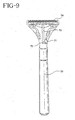
- FIG. 8 and 9 Further alternative embodiments, not forming part of the invention, of an in situ sensor comprising a potentiometer are illustrated in Figures 8 and 9.
- the potentiometer detects changes in the forces applied to the blades upon transfer to the potentiometer shaft. Movement of the potentiometer shaft via a translation, as in a sliding potentiometer, or rotation, as in a potentiometer, results in a change in resistance indicative of the forces applied to the blades. Changes in resistance may be converted into an equivalent voltage change and utilized to activate a device.
- sliding potentiometer 60 is located in handle 30. Potentiometer shaft 61 of the sliding potentiometer receives forces from the blades through the shaving cartridge 63 via piston 62.
- the change in resistance resulting from the movement of the potentiometer shaft along the sliding potentiometer may be converted into an equivalent voltage change and utilized to activate an actuator or indicator or some other device which will movably respond or produce a visual indication to the user.
- a potentiometer 70 is located in handle 30. Forces encountered during shaving arc translated via piston 73 to lever 72 and then onto potentiometer shaft 71. As with the previous embodiment, the translation of the forces will cause the potentiometer to produce a resistance change which may be converted to an equivalent voltage and utilized to activate an actuator or visual indicator in response to the applied shaving forces.
- a combination of receptors may be employed such that either multiple active responses arc produced, multiple passive responses arc produced, or a combination of active and passive responses are produced.
Landscapes
- Life Sciences & Earth Sciences (AREA)
- Forests & Forestry (AREA)
- Engineering & Computer Science (AREA)
- Mechanical Engineering (AREA)
- Dry Shavers And Clippers (AREA)
Description
- This invention relates to the placement of one or more in situ sensors in razor heads, to produce a movement or indication to aid in the quality of the shave. The invention relates to a razor having an in situ sensor.
- Efforts to improve shave quality have been on-going for many years. Much of the effort to improve shave quality has been directed toward making razor cartridges and blades more responsive to the various forces encountered by the razor during shaving. Examples of the results include razor systems having movable components, such as blades, cartridges which flex or bend in response to shaving forces and blades which move inward and outward in response to those forces. One common thread between all previous shaving systems with movable components is that the movements are produced by the function of a mechanical element, such as a spring or pivot. Consequently, one limitation on the function of all of these prior razor systems is that they are only as sensitive as their mechanical elements.
- It would be advantageous to provide a razor system which did not depend upon mechanical elements for sensing the need for movement of the razor components but instead depended upon a more sensitive medium, such as an electronic sensor, to signal that the position of the razor cartridge or the cartridge itself needs changing.
-
US-A-5165170 discloses a razor including an integral hair detection means that provides real-time feedback, during shaving, of areas of beard remaining to be shaved. The razor comprises a razor assembly mounted on a handle for brushing against the surface of a person's face and vibrating in response to contact with hairs thereon; a pickup coupled to the handle responsive to the vibrations produced therein for generating a corresponding signal; and audio frequency amplifying means within the handle for amplifying the signal from the pickup as an audio frequency output. - The invention is defined, broadly, in
independent Claims - The present invention is directed to a wet shave shaving system which contains an in situ sensor within the razor cartridge. The sensor consists of a piezoelectric material which produces an electrical signal when it is strained. In an active feedback system, the signal would be transferred from the cartridge to the razor handle where an electronically-activated actuator would extend or retract as necessary to position the blades to produce a shave with a constant shave force. In a passive feedback system, the signal would be transferred from the cartridge to the razor handle where an electronically-activated element, such as an indicator light, would be activated to produce an indication to the user that he or she should reposition the razor to produce a constant shave force. In an alternative embodiment of the passive feedback system, the signal would provide an indication to the user that the blades are worn and should be replaced.
- Accordingly, it is an advantage of the present invention to provide a razor system having electronic sensors which provide a signal which produces movement to adjust the position of the blades or produces an indication to the user that the blades should be repositioned or replaced.
- There now follows a description of preferred embodiments of the invention, by way of example, with reference being made to the accompanying drawings in which:
- Figure 1 is a top view of a razor cartridge having an in situ sensor;
- Figure 2 is a cut-away view through line 2-2 of the razor cartridge having an in situ sensor;
- Figure 3 is a front view of an alternative embodiment of a razor cartridge having an in situ sensor;
- Figure 4 is a cut-away view through line 4-4 of the razor cartridge having an in situ sensor;
- Figure 4A is a top view of razor handle and a cut-away view of a razor cartridge having an in situ sensor in the handle;
- Figure 5 is top view of a razor handle and a cut-away view of a razor cartridge having an actuator adapted to receive signals from an in situ sensor in a razor cartridge;
- Figure 6a is a top view of a razor handle and cartridge having an actuator in a retracted position;
- Figure 6b is a top view of a razor handle and cartridge having an actuator in an unbiased position;
- Figure 6c is a top view of a razor handle and cartridge having an actuator in an extended position;
- Figure 7 is a top view of a razor handle and cartridge having an indicator light;
- Figure 8 is a top view of a razor handle and a cut-away view of a razor cartridge having a sliding potentiometer; and
- Figure 9 is a top view of a razor handle and a cut-away view of a razor cartridge having a potentiometer.
- Reference will now be made to the presently preferred embodiments of the invention. For the purpose of this application, wet shave razors are defined to be razors which are customarily utilized in conjunction with soap or shaving cream and hot water. The definition of wet shave razors includes both disposable razors, in which the user discards the entire unit after a certain number of uses, and permanent systems, with which the user discards and replaces the razor cartridge after a certain number of uses. In both instances, the razor head, or cartridge, is the portion which surrounds and contains the blade or blades. The combination of the razor head and the handle, either permanent or disposable, is defined as the razor system.
- The present invention provides for a wet shave razor head having one or more in situ sensors which receive and produce a response to the forces encountered by the razor head during shaving. The sensors are constructed from a piezoelectric material which produces an electrical signal when it is strained. A preferred piezoelectric polymer is polyvinylidene fluoride (PVDF) of the type sold by Amp Inc., Valley Forge, Pennsylvania. PVDF is especially preferred as a sensor because it is very flexible and provides a good, strong electrical signal. In addition, PVDF is commercially available in forms of various thickness which facilitates the processing of the material into a sensor which may be placed in virtually any location in a razor system. The piezoelectric polymer sensor is a film which is applied directly to or close to the blades within the razor head.
- Figures 1 and 2
illustrate cartridge 10 having two blades, 11, 12. The in situ sensor, in the form of apiezoelectric polymer film blades wire 18, which receives the electrical signal or signals from the sensor or sensors and then transmits the signals through the razor head to one or more receptors, which are preferably located within the razor handle. - An alternative in situ sensor site is illustrated in Figures 3 and 4. In this embodiment, the in situ sensor is in the form of a solid piece of a
piezoelectric material 23, preferably PVDF or a composite thereof, which is located between the twoblades means 24 to one or more receptors which are preferably located within the razor handle. - In a further embodiment, not forming part of the invention, the sensor may be positioned within the razor handle. In this embodiment, the sensor would indirectly measure the forces on the blade or blades which are transferred to the handle. A preferred embodiment of this alternative illustrated in Figure 4A employs a piezoresistive or
piezoelectric sensor 51 which is placed in thehandle 30. Amovable piston 50 is placed in contact with therazor cartridge 52 or blades and translates the forces encountered during shaving to the sensor. - Figure 5 illustrates the
razor handle 30 of the present invention. The handle, in this case illustrated as a permanent system with a replaceable cartridge, comprises attachment means 32 for the attachment of the razor cartridge,piston 31,conductor 34 and a receptor which is illustrated in Figure 5 in the form ofelectric motor 38. Upon the placement of a razor head on the handle, either permanently or replaceably,conductor 34 is connected to the transmitting means of the razor head to form a circuit and receive the in situ sensor signal through the transmitting means. For disposable razors, the transmitting means of the razor head and the conductor may be a single unit. For permanent systems, the connection is accomplished by placing connectors on the exposed ends of the transmitting means and the conductor so that they attach to each other upon the placement of a razor head on the handle. As with the transmitting means of the razor head, the conductor may be constructed from any suitable conductive material, such as copper wire. - Two different preferred embodiments of receptors exist for receiving and processing the in situ sensor signal and one or more receptors may be employed in each preferred embodiment. The first receptor embodiment is an active system in which the receptor is in the form of a simple signal processing circuit which processes the in situ sensor signal and produces a response to move and position the blades. In the preferred embodiment, the receptor is a signal processing circuit in conjunction with an actuator which is used to move and position the
piston 31. While the actuator may be any means for sufficiently moving the piston, as illustrated the actuator is preferablylead screw 36 which is driven byelectric motor 38 in series withcoupling device 37. Thepiston 31 or a portion of the piston is threaded and rides along the lead screw as the motor responds to the feedback signal generated by the signal processing circuit in response to the in situ sensor.Conductor 34 transmits the electrical signal from the in situ sensor to the signal processing circuit to complete the electrical circuit. Based on the motor's response to the in situ sensor signal,lead screw 36 rotates andpiston 31 correspondingly extends and retracts as necessary to flex the razor head to position the razor head to produce a consistent shave. As illustrated in Figures 6a, 6b and 6c, the expansion of thepiston 31 will flex therazor head 35 into a convex shape while the retraction of the piston will flex the razor head into a concave shape. - The second preferred receptor embodiment, illustrated in Figure 7, is a passive system. In this embodiment one or more sensors, conductors and transmitting means between the razor head and the handle may be as in the previous embodiment. In this embodiment, the receptor in
handle 40 does not produce motion but instead is a signal processing circuit which activates an indicator, such aslight 41. The receptor in the passive system may also activate a light emitting diode (LED) or any other desired indicator. The signal processing circuit receives the electrical signal from the in situ sensors and activates an indicator, such as a light, which provides the user with a visual signal that he or she should take some action. For example, the in situ sensor may be used to differentiate that the user is exerting too much or too little pressure during shaving by generating a comparable electrical signal that would produce a visual indication to the user to change the shaving pressure. In addition. because blades dull over time and thus require more pressure to cut hair, the evolution of additional shaving pressure may be used to indicate that either the disposable razor should be discarded or, in a permanent system, that the razor head should be replaced. In an alternative embodiment, the voltage may be used to activate a device such as a motor or piezoelectric transducer to produce a motion, such as a vibration, or to activate an electric circuit on a circuit board or solid state chip which produces an audible sound, such as notes of a song and/or a human-like voice. In a further alternative embodiment, the passive system may be combined with the active system. For example, the receptor may activate an actuator to produce a constant shave pressure while at the same time lighting an indicator to indicate that the blades are worn and need replacing. - Further alternative embodiments, not forming part of the invention, of an in situ sensor comprising a potentiometer are illustrated in Figures 8 and 9. The potentiometer detects changes in the forces applied to the blades upon transfer to the potentiometer shaft. Movement of the potentiometer shaft via a translation, as in a sliding potentiometer, or rotation, as in a potentiometer, results in a change in resistance indicative of the forces applied to the blades. Changes in resistance may be converted into an equivalent voltage change and utilized to activate a device. In the embodiment of Figure 8, sliding
potentiometer 60 is located inhandle 30.Potentiometer shaft 61 of the sliding potentiometer receives forces from the blades through the shavingcartridge 63 viapiston 62. The change in resistance resulting from the movement of the potentiometer shaft along the sliding potentiometer may be converted into an equivalent voltage change and utilized to activate an actuator or indicator or some other device which will movably respond or produce a visual indication to the user. In the embodiment of Figure 9, a potentiometer 70 is located inhandle 30. Forces encountered during shaving arc translated viapiston 73 to lever 72 and then ontopotentiometer shaft 71. As with the previous embodiment, the translation of the forces will cause the potentiometer to produce a resistance change which may be converted to an equivalent voltage and utilized to activate an actuator or visual indicator in response to the applied shaving forces. In an altemative embodiment, a combination of receptors may be employed such that either multiple active responses arc produced, multiple passive responses arc produced, or a combination of active and passive responses are produced. - While there have been described what are presently believed to be the preferred embodiments of the present invention, those skilled in the art will realize that various changes and modifications may be made to the invention without departing from the invention.
Claims (20)
- A razor system comprising a razor head, having one or more blades (11, 12; 21, 22) and a handle (30; 40), wherein the razor head further comprises one or more in situ sensors for producing one or more signals based on forces encountered during shaving, each of the in situ sensors consisting of piezoelectric material (23) in the form of a polymer film (14, 15) which is directly applied to one or more of the one or more blades (11, 12; 21, 22), the handle (30, 40) further comprising one or more receptors (3 8) for receiving the one or more signals from the one or more in situ sensors and wherein conducting means (18, 34) extend from the one or more in situ sensors to the receptor (38) to provide an electrical circuit between the one or more in situ sensors and the one or more receptors (38).
- A razor system according to Claim 1, wherein the in situ sensors consist of polyvinylidene fluoride.
- A razor system according to any preceding claim, wherein the one or more receptors (38) comprise a signal processing circuit which receives the one or more signals.
- A razor system according to Claim 3, wherein the signal processing circuit is connected to an actuator (31) and wherein the signal processing circuit produces a response to the one or more signals which drives an actuator (31) to move the razor head or the one or more blades (11,12; 21,22) to provide consistent pressure on a surface being shaved.
- A razor system according to Claim 3 or Claim 4 wherein the signal processing circuit is connected to an indicator which produces an indication in response to a feedback signal.
- A razor system according to Claim 5, wherein the indicator comprises a light (41), a light emitting diode, a sound producing device, a motion producing device, or any combination thereof.
- A razor system according to Claim 6, wherein the indicator provides a signal to a user that one or more blades (11,12; 21,22) are worn and need replacement.
- A razor system according to Claim 6 or Claim 7, wherein the indicator provides a signal to a user that the user should apply a different pressure to the razor during shaving.
- A razor system according to any preceding claim, wherein the razor head is permanently attached to the handle (30; 40).
- A razor system according to any of Claims 1 to 8, wherein the razor head is removably attached to the handle (30; 40).
- A razor system comprising a razor head, having at least two blades (11,12; 21,22) and a handle (30; 40), wherein the razor head further comprises one or more in situ sensors for producing one or more signals based on forces encountered during shaving, each of the one or more in situ sensors consisting of piezoelectric material (23) and being in the form of a spacer (23) located between two of the at least two blades, and the handle (30, 40) further comprising one or more receptors (38) for receiving the one or more signals from the one or more in situ sensors and wherein conducting means (18, 34) extend from the one or more in situ sensors to the receptor (38) to provide an electrical circuit between the one or more in situ sensors and the one or more receptors (38).
- A razor head having one or more blades (11,12; 21,22) and one or more in situ sensors for producing a signal based on forces encountered during shaving, each of the in situ sensors consisting of piezoelectric material (23) in the form of a polymer film (14, 15) which is directly applied to one or more of the one or more blades (11,12; 21,22).
- A razor head having at least two blades (11,12; 21,22) and one or more in situ sensors for producing a signal based on forces encountered during shaving, each of the in situ sensors consisting of piezoelectric material (23) and being in the form of a spacer (23) located between two of the at least two blades.
- A razor head according to Claim 12 or Claim 13, wherein the in situ sensors consist of polyvinylidene fluoride.
- A razor system according to Claim 1, wherein the one or more receptors (38) comprise a signal processing circuit which produces a feedback signal in response to the in situ sensor signal.
- A razor system according to Claim 15, wherein the signal processing circuit is connectable to an actuator (31) and wherein the signal processing circuit produces a response to at least one in situ sensor signal which drives the actuator (31).
- A razor system according to Claim 15 or Claim 16, wherein the receptor (38) comprises a signal processing circuit and an indicator which produces a feedback signal in response to at least one in situ sensor signal.
- A razor system according to Claim 17, wherein the indicator comprises a light (41), a light emitting diode, a sound producing device, a motion producing device, or any combination thereof.
- A razor system according to Claim 18, wherein the indicator provides a signal to a user that the one or more blades (11,12; 21,22) are worn and need replacement.
- A razor system according to Claim 18 or Claim 19, wherein the indicator provides a signal to a user that the user should apply a different pressure to the razor during shaving.
Applications Claiming Priority (2)
| Application Number | Priority Date | Filing Date | Title |
|---|---|---|---|
| US942527 | 1997-10-02 | ||
| US08/942,527 US6009623A (en) | 1997-10-02 | 1997-10-02 | Razor with in situ sensor |
Publications (3)
| Publication Number | Publication Date |
|---|---|
| EP0906814A1 EP0906814A1 (en) | 1999-04-07 |
| EP0906814B1 EP0906814B1 (en) | 2001-07-18 |
| EP0906814B2 true EP0906814B2 (en) | 2007-06-27 |
Family
ID=25478213
Family Applications (1)
| Application Number | Title | Priority Date | Filing Date |
|---|---|---|---|
| EP98307575A Expired - Lifetime EP0906814B2 (en) | 1997-10-02 | 1998-09-17 | Razor with in situ sensor |
Country Status (6)
| Country | Link |
|---|---|
| US (1) | US6009623A (en) |
| EP (1) | EP0906814B2 (en) |
| JP (1) | JP4446131B2 (en) |
| AU (1) | AU754519B2 (en) |
| CA (1) | CA2246822A1 (en) |
| DE (1) | DE69801141T3 (en) |
Families Citing this family (47)
| Publication number | Priority date | Publication date | Assignee | Title |
|---|---|---|---|---|
| US6460251B1 (en) | 1998-03-25 | 2002-10-08 | Pfizer Inc. | Razor system with worn blade indicator |
| GB2354474B8 (en) * | 1999-09-27 | 2008-01-29 | Gillette Co | Safety razors |
| US6494882B1 (en) * | 2000-07-25 | 2002-12-17 | Verimetra, Inc. | Cutting instrument having integrated sensors |
| WO2002098619A1 (en) * | 2001-05-28 | 2002-12-12 | Matsushita Electric Works, Ltd. | Razor blade |
| US20030055360A1 (en) * | 2001-09-05 | 2003-03-20 | Zeleznik Matthew A. | Minimally invasive sensing system for measuring rigidity of anatomical matter |
| US20040098862A1 (en) * | 2002-08-21 | 2004-05-27 | Eveready Battery Company, Inc. | Razor system having razor sensors |
| US8627573B2 (en) * | 2002-10-05 | 2014-01-14 | Braun Gmbh | Hair-removing device |
| US7654003B2 (en) * | 2003-02-19 | 2010-02-02 | The Gillette Company | Safety razors with charge indicator and power switch |
| GB2398533B (en) * | 2003-02-19 | 2005-11-16 | Gillette Co | Safety razors |
| GB2398534B (en) * | 2003-02-19 | 2005-11-16 | Gillette Co | Safety razors |
| GB0303872D0 (en) * | 2003-02-19 | 2003-03-26 | Gillette Co | Hand held appliances |
| JP2004254757A (en) * | 2003-02-24 | 2004-09-16 | Izumi Products Co | Reciprocating electric razor |
| WO2005056251A1 (en) * | 2003-12-10 | 2005-06-23 | Koninklijke Philips Electronics N.V. | Shaving head with skin stretching member |
| USD509025S1 (en) | 2004-06-09 | 2005-08-30 | American Safety Razor Company | Razor |
| USD509322S1 (en) | 2004-06-09 | 2005-09-06 | American Safety Razor Company | Razor with protective cap |
| USD527491S1 (en) | 2004-06-09 | 2006-08-29 | American Safety Razor Company | Razor lube bar |
| US7100283B1 (en) | 2004-10-18 | 2006-09-05 | Greg Grdodian | Shaving system |
| US7367126B2 (en) * | 2005-09-06 | 2008-05-06 | The Gillette Company | Powered wet-shaving razor |
| WO2007061092A1 (en) * | 2005-11-28 | 2007-05-31 | Taiko Pharmaceutical Co., Ltd. | Countermeasure against infection with floating virus |
| US8065802B2 (en) | 2006-07-14 | 2011-11-29 | The Gillette Company | Shaving razor |
| US20080168657A1 (en) * | 2007-01-12 | 2008-07-17 | Cinzia Simonis Cloke | Razor cartridge measurement apparatus |
| US8061041B2 (en) * | 2007-02-14 | 2011-11-22 | The Gillette Company | Safety razor |
| US20080196251A1 (en) * | 2007-02-15 | 2008-08-21 | The Gillette Company | Support structure for a flexible razor blade assembly |
| US20090119923A1 (en) * | 2007-09-17 | 2009-05-14 | Robert Anthony Hart | Sensor For A Razor |
| US8122606B2 (en) * | 2007-09-17 | 2012-02-28 | The Gillette Company | Cartridge life indicator |
| US8230600B2 (en) * | 2007-09-17 | 2012-07-31 | The Gillette Company | Cartridge detachment sensor |
| PL2218559T3 (en) * | 2009-02-13 | 2013-01-31 | Edgewell Personal Care Brands Llc | Body care device |
| US20120167392A1 (en) * | 2010-12-30 | 2012-07-05 | Stmicroelectronics Pte. Ltd. | Razor with chemical and biological sensor |
| US8495903B1 (en) * | 2011-09-07 | 2013-07-30 | The Boeing Company | Calibration system for a deburring tool |
| WO2014032236A1 (en) * | 2012-08-29 | 2014-03-06 | Ren Xiangrong | Apparatus and method for detecting life of shaving blade, and shaving blade |
| US11040458B2 (en) * | 2012-12-31 | 2021-06-22 | Matthew W. Krenik | Hair cutting device for automated hair cutting system |
| DE202013003009U1 (en) | 2013-04-01 | 2013-06-26 | Axel R. Hidde | Mechanical comfort razor |
| JP6506261B2 (en) * | 2013-05-30 | 2019-04-24 | コーニンクレッカ フィリップス エヌ ヴェKoninklijke Philips N.V. | Device and system for treating hair and / or skin |
| RU2674792C2 (en) * | 2013-11-05 | 2018-12-13 | Конинклейке Филипс Н.В. | Personal care device |
| JP6356341B2 (en) * | 2014-09-26 | 2018-07-11 | コーニンクレッカ フィリップス エヌ ヴェKoninklijke Philips N.V. | Shaving device for body hair |
| JP6509334B2 (en) | 2014-10-07 | 2019-05-08 | コーニンクレッカ フィリップス エヌ ヴェKoninklijke Philips N.V. | Appliance for performing cutting action on hair present in the area of skin |
| WO2016094327A1 (en) * | 2014-12-10 | 2016-06-16 | Haggai Goldfarb | Intelligent shaving system having sensors |
| US11007659B2 (en) | 2014-12-10 | 2021-05-18 | Haggai Goldfarb | Intelligent shaving system having sensors |
| US9914228B1 (en) * | 2016-08-31 | 2018-03-13 | Michael Matthews | Smart clipper |
| US20180126571A1 (en) * | 2016-10-07 | 2018-05-10 | Leigh M. Rothschild | Oral care and grooming device |
| EP3525994B1 (en) | 2016-10-14 | 2020-05-27 | Koninklijke Philips N.V. | Cutting length adjustment mechanism, adjustment drive and hair cutting appliance |
| CN109788989A (en) * | 2016-10-14 | 2019-05-21 | 皇家飞利浦有限公司 | The method of hair cutting apparatus and operation hair cutting apparatus |
| US11192269B2 (en) * | 2017-06-29 | 2021-12-07 | Bic Violex S.A. | System and method for electrically sensing shaving razor blade wear |
| CN110662637B (en) * | 2017-06-29 | 2023-02-28 | 比克维奥莱克斯公司 | Shaver and method for detecting shaving properties |
| EP3829837B8 (en) | 2018-07-31 | 2023-01-11 | BIC Violex Single Member S.A. | Adjustable shaver cartridges and methods thereof |
| US12240134B2 (en) | 2019-07-01 | 2025-03-04 | Spectrum Brands, Inc. | Electric grooming device |
| EP4338901A1 (en) * | 2022-09-13 | 2024-03-20 | BIC Violex Single Member S.A. | Shaving system |
Citations (20)
| Publication number | Priority date | Publication date | Assignee | Title |
|---|---|---|---|---|
| US3274682A (en) † | 1964-02-28 | 1966-09-27 | John H Worthington | Razor with sound detecting means |
| US4168571A (en) † | 1977-02-02 | 1979-09-25 | The Gillette Company | Shaving unit |
| US4675997A (en) † | 1984-12-21 | 1987-06-30 | Matsushita Electric Works, Ltd. | Electric shaver powered by rechargeable batteries |
| US4754548A (en) † | 1985-09-09 | 1988-07-05 | Solow Terry S | Flexible, sectionalized contour razor |
| JPH04105685A (en) † | 1990-08-24 | 1992-04-07 | Matsushita Electric Works Ltd | Electric razor |
| JPH04250189A (en) † | 1991-01-28 | 1992-09-07 | Matsushita Electric Works Ltd | Electric razor |
| JPH04314486A (en) † | 1991-04-15 | 1992-11-05 | Matsushita Electric Works Ltd | Electric razor |
| US5224267A (en) † | 1990-06-11 | 1993-07-06 | The Gillette Company | Safety razors |
| US5251376A (en) † | 1991-07-03 | 1993-10-12 | Wilkinson Sword Gesellschaft Mit Beschrankter Haftung | Razor head, especially razor blade unit of a wet razor |
| US5333383A (en) † | 1990-04-10 | 1994-08-02 | Warner-Lambert Company | Razor handle mechanism with convex-concave slidable cartridge support |
| US5384963A (en) † | 1993-03-27 | 1995-01-31 | Martor-Argentax E. H. Beermann Kg | Razor knife with autoretracting blade |
| WO1995032843A1 (en) † | 1994-06-01 | 1995-12-07 | Philips Electronics N.V. | Shaving apparatus with electrically adjustable cutting unit |
| JPH08117458A (en) † | 1994-10-26 | 1996-05-14 | Matsushita Electric Works Ltd | Electric razor |
| US5621264A (en) † | 1995-08-07 | 1997-04-15 | Ocean Power Technologies, Inc. | Water craft using piezoelectric materials |
| US5627576A (en) † | 1993-01-22 | 1997-05-06 | Sharp Kabushiki Kaisha | Ink jet head using excited progressive waves |
| US5633552A (en) † | 1993-06-04 | 1997-05-27 | The Regents Of The University Of California | Cantilever pressure transducer |
| DE19601780C1 (en) † | 1996-01-19 | 1997-06-26 | Braun Ag | Electric shaver with indicator of maximum deflection of cutting head |
| US5671535A (en) † | 1994-06-01 | 1997-09-30 | U.S. Philips Corporation | Shaving apparatus with controllable motor speed |
| WO1998021112A1 (en) † | 1996-11-11 | 1998-05-22 | Annegret Cordes | Lid for a receptacle |
| US9315883B2 (en) † | 2012-09-14 | 2016-04-19 | Tata Steel Nederland Technology Bv | High strength and low density particle-reinforced steel with improved E-modulus and method for producing said steel |
Family Cites Families (11)
| Publication number | Priority date | Publication date | Assignee | Title |
|---|---|---|---|---|
| US3631595A (en) * | 1970-02-04 | 1972-01-04 | Electrex Corp | Electric shaver |
| GB1367559A (en) * | 1972-08-15 | 1974-09-18 | Wilkinson Sword Ltd | Razor blades |
| AT366946B (en) * | 1980-04-03 | 1982-05-25 | Payer Lux Elektroprod | ELECTRIC SHAVER |
| US5146680A (en) * | 1989-03-21 | 1992-09-15 | Bakhos Youssef G | Shaving apparatus and method |
| NL8903065A (en) * | 1989-12-14 | 1991-07-01 | Philips Nv | ELECTRIC RAZOR. |
| US5500635A (en) * | 1990-02-20 | 1996-03-19 | Mott; Jonathan C. | Products incorporating piezoelectric material |
| IL96274A0 (en) * | 1990-11-08 | 1991-08-16 | Keter Plastic Ltd | Razor having integral hair detection means |
| JPH07102260B2 (en) * | 1991-09-20 | 1995-11-08 | フェザー安全剃刀株式会社 | Safety razor |
| AT403958B (en) * | 1992-02-17 | 1998-07-27 | Payer Lux Elektroprod | ELECTRIC SHAVER |
| US5347715A (en) * | 1993-09-14 | 1994-09-20 | Friedland Donald H | Blade shave counter |
| US5646470A (en) * | 1994-04-01 | 1997-07-08 | Benthos, Inc. | Acoustic transducer |
-
1997
- 1997-10-02 US US08/942,527 patent/US6009623A/en not_active Expired - Lifetime
-
1998
- 1998-09-04 CA CA002246822A patent/CA2246822A1/en not_active Abandoned
- 1998-09-17 EP EP98307575A patent/EP0906814B2/en not_active Expired - Lifetime
- 1998-09-17 DE DE69801141T patent/DE69801141T3/en not_active Expired - Lifetime
- 1998-09-21 JP JP26604598A patent/JP4446131B2/en not_active Expired - Fee Related
- 1998-09-23 AU AU87025/98A patent/AU754519B2/en not_active Ceased
Patent Citations (20)
| Publication number | Priority date | Publication date | Assignee | Title |
|---|---|---|---|---|
| US3274682A (en) † | 1964-02-28 | 1966-09-27 | John H Worthington | Razor with sound detecting means |
| US4168571A (en) † | 1977-02-02 | 1979-09-25 | The Gillette Company | Shaving unit |
| US4675997A (en) † | 1984-12-21 | 1987-06-30 | Matsushita Electric Works, Ltd. | Electric shaver powered by rechargeable batteries |
| US4754548A (en) † | 1985-09-09 | 1988-07-05 | Solow Terry S | Flexible, sectionalized contour razor |
| US5333383A (en) † | 1990-04-10 | 1994-08-02 | Warner-Lambert Company | Razor handle mechanism with convex-concave slidable cartridge support |
| US5224267A (en) † | 1990-06-11 | 1993-07-06 | The Gillette Company | Safety razors |
| JPH04105685A (en) † | 1990-08-24 | 1992-04-07 | Matsushita Electric Works Ltd | Electric razor |
| JPH04250189A (en) † | 1991-01-28 | 1992-09-07 | Matsushita Electric Works Ltd | Electric razor |
| JPH04314486A (en) † | 1991-04-15 | 1992-11-05 | Matsushita Electric Works Ltd | Electric razor |
| US5251376A (en) † | 1991-07-03 | 1993-10-12 | Wilkinson Sword Gesellschaft Mit Beschrankter Haftung | Razor head, especially razor blade unit of a wet razor |
| US5627576A (en) † | 1993-01-22 | 1997-05-06 | Sharp Kabushiki Kaisha | Ink jet head using excited progressive waves |
| US5384963A (en) † | 1993-03-27 | 1995-01-31 | Martor-Argentax E. H. Beermann Kg | Razor knife with autoretracting blade |
| US5633552A (en) † | 1993-06-04 | 1997-05-27 | The Regents Of The University Of California | Cantilever pressure transducer |
| WO1995032843A1 (en) † | 1994-06-01 | 1995-12-07 | Philips Electronics N.V. | Shaving apparatus with electrically adjustable cutting unit |
| US5671535A (en) † | 1994-06-01 | 1997-09-30 | U.S. Philips Corporation | Shaving apparatus with controllable motor speed |
| JPH08117458A (en) † | 1994-10-26 | 1996-05-14 | Matsushita Electric Works Ltd | Electric razor |
| US5621264A (en) † | 1995-08-07 | 1997-04-15 | Ocean Power Technologies, Inc. | Water craft using piezoelectric materials |
| DE19601780C1 (en) † | 1996-01-19 | 1997-06-26 | Braun Ag | Electric shaver with indicator of maximum deflection of cutting head |
| WO1998021112A1 (en) † | 1996-11-11 | 1998-05-22 | Annegret Cordes | Lid for a receptacle |
| US9315883B2 (en) † | 2012-09-14 | 2016-04-19 | Tata Steel Nederland Technology Bv | High strength and low density particle-reinforced steel with improved E-modulus and method for producing said steel |
Non-Patent Citations (1)
| Title |
|---|
| Statement of grounds of appeal dated July 19, 2004, page 485 † |
Also Published As
| Publication number | Publication date |
|---|---|
| CA2246822A1 (en) | 1999-04-02 |
| EP0906814B1 (en) | 2001-07-18 |
| EP0906814A1 (en) | 1999-04-07 |
| AU8702598A (en) | 1999-04-22 |
| DE69801141T3 (en) | 2007-11-22 |
| DE69801141T2 (en) | 2002-03-21 |
| AU754519B2 (en) | 2002-11-21 |
| DE69801141D1 (en) | 2001-08-23 |
| JP4446131B2 (en) | 2010-04-07 |
| JPH11156069A (en) | 1999-06-15 |
| US6009623A (en) | 2000-01-04 |
Similar Documents
| Publication | Publication Date | Title |
|---|---|---|
| EP0906814B2 (en) | Razor with in situ sensor | |
| EP1556191B1 (en) | Razor system having razor sensors | |
| EP0945229B1 (en) | Razor system with worn blade indicator | |
| EP2691037B1 (en) | Ultrasonic surgical instruments | |
| EP2828046B1 (en) | Shaver having adaptive skin engaging surface | |
| US20110197726A1 (en) | Electrically Operated Shaver | |
| GB2030909A (en) | Razors | |
| US20240033959A1 (en) | Shaving head | |
| US20240083050A1 (en) | Shaving system | |
| JP7542754B2 (en) | Hair detection in hair cutting systems | |
| CN221736223U (en) | Shaving device with pressure feedback function | |
| EP3829837B1 (en) | Adjustable shaver cartridges and methods thereof | |
| WO2025257770A1 (en) | Method for detecting hair cutting events during use of a wet shaver and wet shaver | |
| JPH04295392A (en) | Electric razor blade |
Legal Events
| Date | Code | Title | Description |
|---|---|---|---|
| PUAI | Public reference made under article 153(3) epc to a published international application that has entered the european phase |
Free format text: ORIGINAL CODE: 0009012 |
|
| AK | Designated contracting states |
Kind code of ref document: A1 Designated state(s): DE FR GB |
|
| AX | Request for extension of the european patent |
Free format text: AL;LT;LV;MK;RO;SI |
|
| 17P | Request for examination filed |
Effective date: 19991007 |
|
| AKX | Designation fees paid |
Free format text: DE FR GB |
|
| 17Q | First examination report despatched |
Effective date: 20000410 |
|
| GRAG | Despatch of communication of intention to grant |
Free format text: ORIGINAL CODE: EPIDOS AGRA |
|
| GRAG | Despatch of communication of intention to grant |
Free format text: ORIGINAL CODE: EPIDOS AGRA |
|
| GRAH | Despatch of communication of intention to grant a patent |
Free format text: ORIGINAL CODE: EPIDOS IGRA |
|
| GRAH | Despatch of communication of intention to grant a patent |
Free format text: ORIGINAL CODE: EPIDOS IGRA |
|
| GRAA | (expected) grant |
Free format text: ORIGINAL CODE: 0009210 |
|
| AK | Designated contracting states |
Kind code of ref document: B1 Designated state(s): DE FR GB |
|
| REF | Corresponds to: |
Ref document number: 69801141 Country of ref document: DE Date of ref document: 20010823 |
|
| ET | Fr: translation filed | ||
| REG | Reference to a national code |
Ref country code: GB Ref legal event code: IF02 |
|
| PLBQ | Unpublished change to opponent data |
Free format text: ORIGINAL CODE: EPIDOS OPPO |
|
| PLBI | Opposition filed |
Free format text: ORIGINAL CODE: 0009260 |
|
| PLBF | Reply of patent proprietor to notice(s) of opposition |
Free format text: ORIGINAL CODE: EPIDOS OBSO |
|
| 26 | Opposition filed |
Opponent name: THE GILLETTE COMPANY Effective date: 20020418 |
|
| PLBF | Reply of patent proprietor to notice(s) of opposition |
Free format text: ORIGINAL CODE: EPIDOS OBSO |
|
| PLBF | Reply of patent proprietor to notice(s) of opposition |
Free format text: ORIGINAL CODE: EPIDOS OBSO |
|
| PLBF | Reply of patent proprietor to notice(s) of opposition |
Free format text: ORIGINAL CODE: EPIDOS OBSO |
|
| PLBF | Reply of patent proprietor to notice(s) of opposition |
Free format text: ORIGINAL CODE: EPIDOS OBSO |
|
| PGFP | Annual fee paid to national office [announced via postgrant information from national office to epo] |
Ref country code: FR Payment date: 20030703 Year of fee payment: 6 |
|
| PLAY | Examination report in opposition despatched + time limit |
Free format text: ORIGINAL CODE: EPIDOSNORE2 |
|
| PLBC | Reply to examination report in opposition received |
Free format text: ORIGINAL CODE: EPIDOSNORE3 |
|
| APBP | Date of receipt of notice of appeal recorded |
Free format text: ORIGINAL CODE: EPIDOSNNOA2O |
|
| APBP | Date of receipt of notice of appeal recorded |
Free format text: ORIGINAL CODE: EPIDOSNNOA2O |
|
| APBQ | Date of receipt of statement of grounds of appeal recorded |
Free format text: ORIGINAL CODE: EPIDOSNNOA3O |
|
| APAA | Appeal reference recorded |
Free format text: ORIGINAL CODE: EPIDOS REFN |
|
| PG25 | Lapsed in a contracting state [announced via postgrant information from national office to epo] |
Ref country code: FR Free format text: LAPSE BECAUSE OF NON-PAYMENT OF DUE FEES Effective date: 20050531 |
|
| RAP2 | Party data changed (patent owner data changed or rights of a patent transferred) |
Owner name: WARNER-LAMBERT COMPANY LLC |
|
| REG | Reference to a national code |
Ref country code: FR Ref legal event code: ST |
|
| APAH | Appeal reference modified |
Free format text: ORIGINAL CODE: EPIDOSCREFNO |
|
| APBU | Appeal procedure closed |
Free format text: ORIGINAL CODE: EPIDOSNNOA9O |
|
| RAP2 | Party data changed (patent owner data changed or rights of a patent transferred) |
Owner name: WARNER-LAMBERT COMPANY LLC |
|
| PUAH | Patent maintained in amended form |
Free format text: ORIGINAL CODE: 0009272 |
|
| STAA | Information on the status of an ep patent application or granted ep patent |
Free format text: STATUS: PATENT MAINTAINED AS AMENDED |
|
| 27A | Patent maintained in amended form |
Effective date: 20070627 |
|
| AK | Designated contracting states |
Kind code of ref document: B2 Designated state(s): DE FR GB |
|
| EN | Fr: translation not filed | ||
| PGFP | Annual fee paid to national office [announced via postgrant information from national office to epo] |
Ref country code: GB Payment date: 20160927 Year of fee payment: 19 |
|
| PGFP | Annual fee paid to national office [announced via postgrant information from national office to epo] |
Ref country code: DE Payment date: 20160928 Year of fee payment: 19 |
|
| REG | Reference to a national code |
Ref country code: DE Ref legal event code: R119 Ref document number: 69801141 Country of ref document: DE |
|
| GBPC | Gb: european patent ceased through non-payment of renewal fee |
Effective date: 20170917 |
|
| PG25 | Lapsed in a contracting state [announced via postgrant information from national office to epo] |
Ref country code: GB Free format text: LAPSE BECAUSE OF NON-PAYMENT OF DUE FEES Effective date: 20170917 Ref country code: DE Free format text: LAPSE BECAUSE OF NON-PAYMENT OF DUE FEES Effective date: 20180404 |