EP0906794B1 - Long products sorting system - Google Patents
Long products sorting system Download PDFInfo
- Publication number
- EP0906794B1 EP0906794B1 EP98307381A EP98307381A EP0906794B1 EP 0906794 B1 EP0906794 B1 EP 0906794B1 EP 98307381 A EP98307381 A EP 98307381A EP 98307381 A EP98307381 A EP 98307381A EP 0906794 B1 EP0906794 B1 EP 0906794B1
- Authority
- EP
- European Patent Office
- Prior art keywords
- conveyor
- long product
- long
- receiving
- sorting system
- Prior art date
- Legal status (The legal status is an assumption and is not a legal conclusion. Google has not performed a legal analysis and makes no representation as to the accuracy of the status listed.)
- Expired - Lifetime
Links
Images


Classifications
-
- B—PERFORMING OPERATIONS; TRANSPORTING
- B23—MACHINE TOOLS; METAL-WORKING NOT OTHERWISE PROVIDED FOR
- B23Q—DETAILS, COMPONENTS, OR ACCESSORIES FOR MACHINE TOOLS, e.g. ARRANGEMENTS FOR COPYING OR CONTROLLING; MACHINE TOOLS IN GENERAL CHARACTERISED BY THE CONSTRUCTION OF PARTICULAR DETAILS OR COMPONENTS; COMBINATIONS OR ASSOCIATIONS OF METAL-WORKING MACHINES, NOT DIRECTED TO A PARTICULAR RESULT
- B23Q17/00—Arrangements for observing, indicating or measuring on machine tools
- B23Q17/20—Arrangements for observing, indicating or measuring on machine tools for indicating or measuring workpiece characteristics, e.g. contour, dimension, hardness
-
- B—PERFORMING OPERATIONS; TRANSPORTING
- B07—SEPARATING SOLIDS FROM SOLIDS; SORTING
- B07C—POSTAL SORTING; SORTING INDIVIDUAL ARTICLES, OR BULK MATERIAL FIT TO BE SORTED PIECE-MEAL, e.g. BY PICKING
- B07C5/00—Sorting according to a characteristic or feature of the articles or material being sorted, e.g. by control effected by devices which detect or measure such characteristic or feature; Sorting by manually actuated devices, e.g. switches
- B07C5/04—Sorting according to size
- B07C5/12—Sorting according to size characterised by the application to particular articles, not otherwise provided for
-
- B—PERFORMING OPERATIONS; TRANSPORTING
- B07—SEPARATING SOLIDS FROM SOLIDS; SORTING
- B07C—POSTAL SORTING; SORTING INDIVIDUAL ARTICLES, OR BULK MATERIAL FIT TO BE SORTED PIECE-MEAL, e.g. BY PICKING
- B07C5/00—Sorting according to a characteristic or feature of the articles or material being sorted, e.g. by control effected by devices which detect or measure such characteristic or feature; Sorting by manually actuated devices, e.g. switches
- B07C5/36—Sorting apparatus characterised by the means used for distribution
- B07C5/361—Processing or control devices therefor, e.g. escort memory
- B07C5/362—Separating or distributor mechanisms
-
- B—PERFORMING OPERATIONS; TRANSPORTING
- B23—MACHINE TOOLS; METAL-WORKING NOT OTHERWISE PROVIDED FOR
- B23Q—DETAILS, COMPONENTS, OR ACCESSORIES FOR MACHINE TOOLS, e.g. ARRANGEMENTS FOR COPYING OR CONTROLLING; MACHINE TOOLS IN GENERAL CHARACTERISED BY THE CONSTRUCTION OF PARTICULAR DETAILS OR COMPONENTS; COMBINATIONS OR ASSOCIATIONS OF METAL-WORKING MACHINES, NOT DIRECTED TO A PARTICULAR RESULT
- B23Q7/00—Arrangements for handling work specially combined with or arranged in, or specially adapted for use in connection with, machine tools, e.g. for conveying, loading, positioning, discharging, sorting
- B23Q7/12—Sorting arrangements
-
- B—PERFORMING OPERATIONS; TRANSPORTING
- B21—MECHANICAL METAL-WORKING WITHOUT ESSENTIALLY REMOVING MATERIAL; PUNCHING METAL
- B21B—ROLLING OF METAL
- B21B39/00—Arrangements for moving, supporting, or positioning work, or controlling its movement, combined with or arranged in, or specially adapted for use in connection with, metal-rolling mills
- B21B39/002—Piling, unpiling, unscrambling
Definitions
- the present invention relates to a long-product sorting system.
- the present invention pertains to a system for sorting in-between-length and remnant long-products efficiently and automatically.
- Such systems are known, for instance , from AT 358836, GB 2 170 187 or US 3 085 686.
- FIG. 1 is the top plan elevational view of an embodiment of the present invention.
- FIGS. 2A and B are front and right side views respectively of the measuring table of the long product sorting system embodying the present invention.
- FIGS. 3A and 3B are front elevational views of the conveyor assembly of the long product sorting system.
- FIG. 3C is the right side, cross sectional view of the stopper and kicker assemblies of the conveyor assembly according to section A - A in FIG. 3B
- FIG 4A is a front elevational view of the extended conveyor assembly of the long product sorting system embodying the present invention.
- FIG. 4B is the right side, cross sectional view of the stopper and kicker assembly according to section B - B of the extended conveyor assembly.
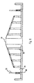
- FIG. 5A is a top plan view of the bin embodying the present invention.
- FIG. 58 is an enlarged view of one frame of a bins section.
- FIG. 5C is the right cross-sectional view of the bins section embodying the present invention according to section C - C in FIG. 5A.
- FIG. 6 is the right side plan view of the dual bins of the extended conveyor assembly embodying the present invention.
- FIGS 7A and 7B are flowcharts illustrating the logic of a controller for the long product sorting system embodying the present invention.
- Embodiments of the present invention provide a method and apparatus for sorting long products of varying lengths automatically.
- the system features various functional modules.
- the first module functions to measure the length of the product to be sorted.
- One embodiment of this module includes a sorting table having a sorting area and a measuring unit.
- the second module functions to transfer the measured product to the proximity of the correct storage bin.
- One embodiment of this second module is a conveyor system.
- the third module includes a group of storage bins disposed in parallel to the conveyor, the bins in each group having descending heights to utilize gravity as the moving force for the product to roll or slide down along the bin covers. A retractable bin cover or lever can be raised to allow the bin to receive the product.
- the system may be automated using a computer algorithm.
- the system includes a sorting table 20 having a sorting area 22 and a measuring unit 24, a conveyor system 26 having a primary conveyor section 28 and secondary conveyor section 30, three groups of bins in sections 1, 2 and 3 (reference numerals 32, 34 and 36 ) respectively, and a control and display panel with a personal computer 38.
- Another embodiment would consist of only the primary conveyor section if a small number of bins are used.
- Other embodiments are envisioned whereby additional conveyor sections and groups of bins may be added to accommodate more types of long products of different lengths.
- the sorting area is a table. Other structures or an open area can also be used to retain the product for convenient sorting.
- the sorting table 20 includes a series of measuring sensors 44 mounted on the measuring unit 24 for sensing the length of the objects put on the surface of the sorting area 22.
- a set of mechanical pushers 40 are provided to transfer the measured product onto the conveyor system.
- the pushers 40 are located adjacent to the sensors 44 and mechanically operated with a pneumatic cylinder 42 , and a guide 46.
- an inductance proximity sensor is used.
- the pushers may also be operated by hydraulic or electrical means.
- modifications within the knowledge of one of ordinary skill in the art may be made to use optical or image processing methods for measurement.
- Figures 3A to C show an example of the primary conveyor section 28 adjacent to the section 1 primary group of bins.
- the conveyor includes a stopper plate and a series of kicker plates.
- the stoppers or kickers are plates which are provided perpendicular to the conveying direction of the conveyor system.
- the stopper plate aligns a product in the correct position along the conveying direction before it is "kicked" into the bin. It also functions as a gate to prevent the product in the primary conveyor from entering the secondary conveyor if the latter has a product already deposited there.
- the stopper/kicker plates 48 are trapezoidal in shape, and have their upper surfaces 50 sloping downwards towards the primary bins section.
- each stopper and kicker assembly is provided with a pneumatic cylinder 52, kicker plate 48 and guide support 54 and conventional means for the mechanical extension of the plate.
- a product that is transferred to the conveyor system would travel unimpeded along the conveyor.
- the stopper plate is switched to a projected position before the product arrives, then it acts as a stopper to prevent the product from moving further down the conveyor system.
- the kicker plates located directly below that product would be switched to a projected position.
- the product would be "kicked" off the conveyor system onto section 1 containing a group of bins.
- Figures 3A shows all the plates in the extended position.
- Figure 4A shows a segment of the secondary conveyor section 30 .
- the secondary conveyor section as discussed above acts as a extended conveyor and is situated between the sections 2 and 3 bins sections.
- the kicker assemblies In order for the kicker assemblies to function bidirectionally, i.e. kicking the product either to bins section 2 on one side or bins section 3 on the other side, two sets of kicker/stoppers are required in this secondary conveyor section.
- One type have plates 56 with the upper surface 58 sloping downwards in one direction, and another type with plates 60 with the upper surface 62 sloping downwards in the other direction. In this embodiment, any of the plates may function as a stopper.
- the bins sections according to one embodiment of the present invention comprises a plurality of elongated bins aligned in parallel with the conveyor.
- the bins are arranged in descending heights starting from the edge of the conveyor.
- the cover of each bin maintains a sloped configuration when closed whereby gravity causes the long product to roll or slide down the closed lever cover.
- the lever cover of the correct bin is switched to an open position and those of the wrong bins to a closed position before the product is pushed off the conveyor, such that the product would roll over the closed bins until it drops into the open bin.
- Figure 5A to C shows the preferred embodiment of a bins section in accordance with the present invention.
- a sliding plate 64 serves as a platform from where a product "kicked" from the conveyor would roll past. It allows the products to roll down from the conveyor effectively.
- a plurality of elongated support pillars 66 are provided adjacent to the support beam. The support pillars are aligned to support a structure of levers 68 .
- the bins 70 are spaces provided between the support pillars. These bins have descending heights starting from the sliding plate. The levers can be switched to an open position, where upon products may be dropped into the bin below.
- lever 72 is in the open position, resulting in the product being dropped into bin 74 , when the product is "kicked” off to the left of the conveyor by appropriate kickers.
- the levers are operated with pneumatic cylinders 76 and actuators by conventional mechanical means.
- Figures 7A and B shows a computer method for the automation of the equipment and method described above.
- the switches for the control of the various equipment are connected to a control and display station.
- the system When the power of the control unit is switched on 105, the system to go through a self-check process 107.
- the first step of the operation is the input from the operator as to whether there is any remaining bundle In the current batch or a new batch is to be started 113. If there is no unsorted bundle in the current batch, i.e. the current batch has been completely sorted, a Change New Batch Routine 115 is performed to allow the entry of all the necessary batch and product information required by the system. If there are still bundles remaining in the current batch, the operator is prompted for whether current infeed unsorted bundle is completed 117.
- step 121 If there are still products in the current bundle, the operation proceeds to step 121. However, if the current infeed unsorted bundle is completed, the Change Bundle Routine 119 is performed. All necessary bundle information are input to the system. When all information has been entered, the operation proceeds to step 121. The conveyor system will be switched on at step 121. All kickers, stoppers and pushers will be retracted to the home position 123. All bin covers are also activated to the closed position. The system control 125 checks to ensure all pushers are down before switching on the "PUT IN" light 127 to signal to the operator that the system is ready for him to throw in a new product.
- the system checks the signal feedback by measurements made by the measuring sensors to determine the presence or absence of a product, and to check 131 if the product length is a valid length 133. If the length is valid, implying that there is a suitable product in the measuring unit, the "PUT IN" light is turned off 139, signaling to the operator not to throw any new product into the measuring unit. However, if the system detects an invalid length, a warning is issued 135, and the control loops back 103 to step 121.
- the length of the product is calculated 141.
- the correct section, sorting bin and stopper to be activated are identified in step 143.
- the number of product in the identified bin and the current sorted bundle are determined in step 145. If the current sorted bundle in this bin is full 147, a New Sorted Bundle Subroutine is performed. This subroutine temporarily stops the system such that the operator can physically bundle up the complete bundle. If the current bin is full 151, a Clear Bin Subroutine is performed. This subroutine stops the machine and allows clearing of any bundle in all bins. If both current sorted bundle and bin are not full, Section 1 stopper will be raised in step 155 to confine the product to section 1. The system confirms in step 157 that the stopper is up before raising the pushers in step 159, which causes the product to be pushed into the conveyor.
- step 163 After some time delay 161, all pushers are retracted in step 163. Depending on the section the product is supposed to go, the sequence deviates after step 165. If the correct section is section 2 or section 3, section 1 stopper will be retracted in step 171 to allow for the product to pass through. The correct stopper within section 2 or 3 will also be raised 173 to stop and position the product which would be traveling down the secondary conveyor after being released by the lowered section 1 stopper. Step 175 sends a signal to the correct bin cover for the lever to open. All kickers are then raised in step 177 to push the product out of the conveyor where it rolls or slides down into the designated bin. After some time delay 187 to allow the product time to drop into the bin, the bin cover is closed 189 . At the same time, the system ensure that the kickers are fully raised and subsequently fully retracted using steps 177-185.
- the product is sorted, and the system updates the production data 191. If the current infeed unsorted bundle is completed and a new bundle is to be sorted 193, the system will update 195 the production data by decreasing the number of unsorted bundle by one and the program loops 101 to step 113. If the current infeed unsorted bundle is not complete, the operation loops back 103 to step 121 and prompts the operator to throw in a new product.
- each support pillar have been described in the above examples as being designated for product for one length, it is possible that each channel may be subdivided to store products of different lengths. This is accomplished by using stopper plates at different positions to confine a product to a particular segment or frame within a bin.
Description
- The present invention relates to a long-product sorting system. In particular, the present invention pertains to a system for sorting in-between-length and remnant long-products efficiently and automatically.
- Such systems are known, for instance , from AT 358836,
GB 2 170 187 or US 3 085 686. - It is well known in long product rolling mills and downstream fabrication of bars that odd-length long products are generated. Traditionally, such long products are either recycled to the melt shop as scrap or sorted manually and grouped according to length. The recycling process is inefficient while the manual sorting process is time consuming and labor intensive.
- It is an aim of the present invention to sort odd length bars and long products automatically to the closest predetermined stock length.
- It is another aim of the present invention to reduce the labor input in long product sorting operation.
- It is yet another aim of the present invention to modularize long product sorting system whose length resolution of sorted long products is adjustable.
- According to one aspect of the present invention, there is provided a long product sorting system as described in
claim 1. - According to another aspect of the invention, there is provided a method of sorting long products as described in claim 16.
- FIG. 1 is the top plan elevational view of an embodiment of the present invention.
- FIGS. 2A and B are front and right side views respectively of the measuring table of the long product sorting system embodying the present invention.
- FIGS. 3A and 3B are front elevational views of the conveyor assembly of the long product sorting system.
- FIG. 3C is the right side, cross sectional view of the stopper and kicker assemblies of the conveyor assembly according to section A - A in FIG. 3B
- FIG 4A is a front elevational view of the extended conveyor assembly of the long product sorting system embodying the present invention.
- FIG. 4B is the right side, cross sectional view of the stopper and kicker assembly according to section B - B of the extended conveyor assembly.
- FIG. 5A is a top plan view of the bin embodying the present invention.
- FIG. 58 is an enlarged view of one frame of a bins section.
- FIG. 5C is the right cross-sectional view of the bins section embodying the present invention according to section C - C in FIG. 5A.
- FIG. 6 is the right side plan view of the dual bins of the extended conveyor assembly embodying the present invention.
- FIGS 7A and 7B are flowcharts illustrating the logic of a controller for the long product sorting system embodying the present invention.
- Embodiments of the present invention provide a method and apparatus for sorting long products of varying lengths automatically. The system features various functional modules. The first module functions to measure the length of the product to be sorted. One embodiment of this module includes a sorting table having a sorting area and a measuring unit. The second module functions to transfer the measured product to the proximity of the correct storage bin. One embodiment of this second module is a conveyor system. The third module includes a group of storage bins disposed in parallel to the conveyor, the bins in each group having descending heights to utilize gravity as the moving force for the product to roll or slide down along the bin covers. A retractable bin cover or lever can be raised to allow the bin to receive the product. The system may be automated using a computer algorithm.
- In the following description, numerous specific details are set forth such as mechanical parts and computer program steps, etc. in order to provide a thorough understanding of the present invention. It will be obvious to one skilled in the art that embodiments of the present invention maybe practiced without these specific details. In other instances, well-known parts such as those involved with the physical connection between the measuring sensors and the controller are not shown in order not to obscure the description of the embodiments of the present invention.
- One embodiment of the present invention is shown in Figure 1. In this example, the system includes a sorting table 20 having a
sorting area 22 and ameasuring unit 24, aconveyor system 26 having aprimary conveyor section 28 andsecondary conveyor section 30, three groups of bins insections reference numerals 32, 34 and 36) respectively, and a control and display panel with apersonal computer 38. Another embodiment would consist of only the primary conveyor section if a small number of bins are used. Other embodiments are envisioned whereby additional conveyor sections and groups of bins may be added to accommodate more types of long products of different lengths. In the embodiment given in Figure 1, the sorting area is a table. Other structures or an open area can also be used to retain the product for convenient sorting. - Referring to Figures 2A and B, the sorting table 20 includes a series of measuring
sensors 44 mounted on themeasuring unit 24 for sensing the length of the objects put on the surface of thesorting area 22. A set ofmechanical pushers 40 are provided to transfer the measured product onto the conveyor system. In this example, thepushers 40 are located adjacent to thesensors 44 and mechanically operated with apneumatic cylinder 42, and aguide 46. In the preferred embodiment, an inductance proximity sensor is used. However, it is possible to use other sensors, or even contact-type limit switches to practice embodiments of the present invention. The pushers may also be operated by hydraulic or electrical means. In addition, modifications within the knowledge of one of ordinary skill in the art may be made to use optical or image processing methods for measurement. - Figures 3A to C show an example of the
primary conveyor section 28 adjacent to thesection 1 primary group of bins. The conveyor includes a stopper plate and a series of kicker plates. The stoppers or kickers are plates which are provided perpendicular to the conveying direction of the conveyor system. The stopper plate aligns a product in the correct position along the conveying direction before it is "kicked" into the bin. It also functions as a gate to prevent the product in the primary conveyor from entering the secondary conveyor if the latter has a product already deposited there. The stopper/kicker plates 48 are trapezoidal in shape, and have theirupper surfaces 50 sloping downwards towards the primary bins section. In the example shown in Figures 3B and C, each stopper and kicker assembly is provided with apneumatic cylinder 52,kicker plate 48 andguide support 54 and conventional means for the mechanical extension of the plate. When the stopper plate is in its retracted positions, a product that is transferred to the conveyor system would travel unimpeded along the conveyor. When the stopper plate is switched to a projected position before the product arrives, then it acts as a stopper to prevent the product from moving further down the conveyor system. Then to direct the product into a suitable bin, the kicker plates located directly below that product would be switched to a projected position. As the upper surface of each plate is downward sloping, the product would be "kicked" off the conveyor system ontosection 1 containing a group of bins. Figures 3A shows all the plates in the extended position. - Figure 4A shows a segment of the
secondary conveyor section 30. In this example, the secondary conveyor section as discussed above acts as a extended conveyor and is situated between thesections bins section 2 on one side orbins section 3 on the other side, two sets of kicker/stoppers are required in this secondary conveyor section. One type haveplates 56 with theupper surface 58 sloping downwards in one direction, and another type withplates 60 with theupper surface 62 sloping downwards in the other direction. In this embodiment, any of the plates may function as a stopper. Once the product has been stopped at the appropriate position, the correct set of kickers are raised to "kick" the product to the correct bins section. - The bins sections according to one embodiment of the present invention comprises a plurality of elongated bins aligned in parallel with the conveyor. The bins are arranged in descending heights starting from the edge of the conveyor. The cover of each bin maintains a sloped configuration when closed whereby gravity causes the long product to roll or slide down the closed lever cover. The lever cover of the correct bin is switched to an open position and those of the wrong bins to a closed position before the product is pushed off the conveyor, such that the product would roll over the closed bins until it drops into the open bin.
- Figure 5A to C shows the preferred embodiment of a bins section in accordance with the present invention. In this example, a sliding
plate 64 serves as a platform from where a product "kicked" from the conveyor would roll past. It allows the products to roll down from the conveyor effectively. A plurality ofelongated support pillars 66 are provided adjacent to the support beam. The support pillars are aligned to support a structure oflevers 68. Thebins 70 are spaces provided between the support pillars. These bins have descending heights starting from the sliding plate. The levers can be switched to an open position, where upon products may be dropped into the bin below. Referring to Figure 6,lever 72 is in the open position, resulting in the product being dropped intobin 74, when the product is "kicked" off to the left of the conveyor by appropriate kickers. The levers are operated withpneumatic cylinders 76 and actuators by conventional mechanical means. - Figures 7A and B shows a computer method for the automation of the equipment and method described above. The switches for the control of the various equipment are connected to a control and display station. When the power of the control unit is switched on 105, the system to go through a self-
check process 107. The first step of the operation is the input from the operator as to whether there is any remaining bundle In the current batch or a new batch is to be started 113. If there is no unsorted bundle in the current batch, i.e. the current batch has been completely sorted, a ChangeNew Batch Routine 115 is performed to allow the entry of all the necessary batch and product information required by the system. If there are still bundles remaining in the current batch, the operator is prompted for whether current infeed unsorted bundle is completed 117. If there are still products in the current bundle, the operation proceeds to step 121. However, if the current infeed unsorted bundle is completed, theChange Bundle Routine 119 is performed. All necessary bundle information are input to the system. When all information has been entered, the operation proceeds to step 121. The conveyor system will be switched on atstep 121. All kickers, stoppers and pushers will be retracted to thehome position 123. All bin covers are also activated to the closed position. Thesystem control 125 checks to ensure all pushers are down before switching on the "PUT IN" light 127 to signal to the operator that the system is ready for him to throw in a new product. In thenext step 129, the system checks the signal feedback by measurements made by the measuring sensors to determine the presence or absence of a product, and to check 131 if the product length is avalid length 133. If the length is valid, implying that there is a suitable product in the measuring unit, the "PUT IN" light is turned off 139, signaling to the operator not to throw any new product into the measuring unit. However, if the system detects an invalid length, a warning is issued 135, and the control loops back 103 to step 121. - As the operation proceeds, the length of the product is calculated 141. Depending on the detected length, the correct section, sorting bin and stopper to be activated are identified in
step 143. The number of product in the identified bin and the current sorted bundle are determined instep 145. If the current sorted bundle in this bin is full 147, a New Sorted Bundle Subroutine is performed. This subroutine temporarily stops the system such that the operator can physically bundle up the complete bundle. If the current bin is full 151, a Clear Bin Subroutine is performed. This subroutine stops the machine and allows clearing of any bundle in all bins. If both current sorted bundle and bin are not full,Section 1 stopper will be raised instep 155 to confine the product tosection 1. The system confirms instep 157 that the stopper is up before raising the pushers instep 159, which causes the product to be pushed into the conveyor. - After some
time delay 161, all pushers are retracted instep 163. Depending on the section the product is supposed to go, the sequence deviates afterstep 165. If the correct section issection 2 orsection 3,section 1 stopper will be retracted instep 171 to allow for the product to pass through. The correct stopper withinsection section 1 stopper. Step 175 sends a signal to the correct bin cover for the lever to open. All kickers are then raised instep 177 to push the product out of the conveyor where it rolls or slides down into the designated bin. After sometime delay 187 to allow the product time to drop into the bin, the bin cover is closed 189. At the same time, the system ensure that the kickers are fully raised and subsequently fully retracted using steps 177-185. - At this point, the product is sorted, and the system updates the
production data 191. If the current infeed unsorted bundle is completed and a new bundle is to be sorted 193, the system will update 195 the production data by decreasing the number of unsorted bundle by one and theprogram loops 101 to step 113. If the current infeed unsorted bundle is not complete, the operation loops back 103 to step 121 and prompts the operator to throw in a new product. - Although each support pillar have been described in the above examples as being designated for product for one length, it is possible that each channel may be subdivided to store products of different lengths. This is accomplished by using stopper plates at different positions to confine a product to a particular segment or frame within a bin.
- While the present invention has been described particularly with references to Figures 1 to 7, with emphasis on a system for sorting long products automatically, it should be understood that the figures are for illustration only and should not be taken as limitation on the invention. In a addition, it is clear that the method and apparatus for the present invention has utility in many applications where automatic long product sorting is required. It is contemplated that many changes and modifications may be made by one of ordinary skill in the art without departing from the scope of the invention as defined in the appended claims.
Claims (20)
- A long product sorting system comprising:whereby said long products are sorted into designated receiving means (70) to the nearest standard length automatically.at least one measuring unit (24) having measuring means for ascertaining the length of each said long product and transferring means for transferring onwards the measured long product; andat least one receiving section proximate said measuring unit (24) and adapted for receiving measured long products transferred by said transferring means therefrom, said receiving section having a plurality of receiving means (70) for receiving thereacross measured long products of similar length, each said receiving means (70) provided with covering means (68) having an open and a close position, said covering means (68) in their closed position adapted to form a sloped top surface across said receiving section such that said measured long products received from said measuring unit (24) can gravitate laterally from the top of one receiving means (70) to the top of the next receiving means (70) along said sloped surface, said covering means (68) further adapted to move to an open position to allow a designated receiving means (70) to receive measured long products,
- The long product sorting system in claim 1 wherein a conveyor (26) is provided between said measuring unit (24) and said receiving section, said conveyor (26) adapted to receive long products from said measuring unit (24) and to transfer long products to said receiving section therealong.
- The long product sorting system in claim 2 wherein the conveyor (26) is aligned longitudinally between said measuring unit (24) and the top edge of said sloped surface of said receiving area, said conveyor (26) comprisingstopping means disposed along the length of said conveyor (26) for stopping the forward movement of said measured long product along the conveyor (26); andunloading means disposed along the length of said conveyor (26) for unloading the measured long product laterally from said conveyor (26) onto said receiving section.
- The long product sorting system in claim 2 further comprising at least one secondary conveyor (30) proximate at least one secondary receiving section, said secondary conveyor (30) adapted to transferring said long product from said conveyor (26) to at least one secondary receiving section, each secondary receiving section having a plurality of secondary receiving means with covering means, said covering means of said plurality of secondary receiving means joining to form a sloped top surface of said secondary receiving section.
- The long product sorting system in claim 4 wherein the secondary conveyor (30) is aligned longitudinally with the top edge of said sloped surface of said secondary receiving section, said secondary conveyor (30) further aligned axially with said conveyor (26), said secondary conveyor (30) further comprisingwhereby long products may be transferred from said measuring unit (24) to said secondary receiving section via the conveyor (26) and the secondary conveyor (30).stopping means disposed along the length of said secondary conveyor (30) for stopping the forward movement of said measured long product theralong,unloading means disposed along the length of said secondary conveyor (30) for unloading the measured long product laterally from said conveyor (26) onto said receiving section.
- The long product sorting system according to any one of the preceding claims wherein said plurality of receiving means are elongated in shape with the longitudinal sides aligned in parallel, said aligned receiving means further having descending heights with one longitudinal side of the tallest receiving means disposed adjacent to said measuring unit (24) whereby a measured long product being transferred out of said measuring unit (24) by said transferring means will gravitate laterally along said receiving section.
- The long product sorting system according to any one of the preceding claims wherein the covering means is a lever (68) assembly.
- The long product sorting system according to any one of the preceding claims wherein said measuring means is at least one array of measuring sensor s (44).
- The long product sorting system according to any one of the preceding claims wherein said transferring means is an array of pushers.
- The long product sorting system in claim 8 wherein said measuring sensor (44) are spaced at a predetermined distance from each other, said predetermined distance corresponding to the tolerance of said long product sorting system.
- The long product sorting system in claim 8 or 10 wherein said measuring sensor (44) comprises an inductance proximity sensor.
- The long product sorting system in claim 9 wherein said pusher comprises a trapezoidal plate actuated with at least one pneumatic cylinder (42) for transferring said measured long products laterally to said receiving section.
- The long product sorting system in claim 7 wherein said lever (68) assembly comprises a lever hinged on supporting means, said lever further actuated by a pneumatic cylinder (42).
- The long product sorting system in any one of the above claims wherein a measuring table is provided along one side of said measuring unit (24), said measuring table adapted for urging said long products to gravitate towards the side of said measuring unit (24).
- The long product sorting system in any one of the above claims wherein a controller is provided, said controller having at least one input means adapted to receive measurement information, and at least one output means adapted to transmit information.
- A method of sorting long products using a long product sorting system, said system including a measuring unit (24) having sensing means and transferring means, and at least one receiving section having a plurality of receiving means (70) with covering means (68) adapted to move to an open position to allow a designated receiving means (70) to receive measured long products, said covering means (68) forming in their closed position a sloped top surface across said receiving section said method comprising the steps:whereby said long products are sorted to the nearest standard lengths automatically.measuring length of said long product using said measuring means;designating a receiving means (70) for receiving said long product;opening said covering means (68) of said designated receiving means;transferring said long product to said designated receiving means (70) by said transferring means such that said long product is transferred laterally from said measuring unit (24) to said receiving section and travels laterally therealong into said designated receiving means (70),
- The method of claim 16 wherein said method further comprises the step of moving a long product to said measuring unit (24) before said step of measuring length of said long product using said measuring means.
- The method of claim 16 wherein said system further comprises a conveyor (26) having stopping means and unloading means.
- The method of claim 18 wherein said method further comprises the step of designating a stopping means for stopping said long product along said conveyor (26) after said step of measuring length of said long product using said measuring means.
- The method of claim 18 wherein said method further comprising the steps:raising said designated stopping means in said conveyor (26) for stopping said long product at a designated position;transferring said long product to said conveyor (26) using said transferring means; andstopping said long product at the designated position along said conveyor (26) by said stopping means before said step oftransferring said long product to a designated receiving means by raising said unloading means such that said long product is unloaded laterally from said conveyor (26) to said receiving section and travels laterally therealong into the designated receiving means.
Applications Claiming Priority (2)
| Application Number | Priority Date | Filing Date | Title |
|---|---|---|---|
| SG9703427 | 1997-09-16 | ||
| SG1997003427A SG68632A1 (en) | 1997-09-16 | 1997-09-16 | Long product sorting system |
Publications (3)
| Publication Number | Publication Date |
|---|---|
| EP0906794A2 EP0906794A2 (en) | 1999-04-07 |
| EP0906794A3 EP0906794A3 (en) | 1999-07-28 |
| EP0906794B1 true EP0906794B1 (en) | 2003-12-03 |
Family
ID=20429735
Family Applications (1)
| Application Number | Title | Priority Date | Filing Date |
|---|---|---|---|
| EP98307381A Expired - Lifetime EP0906794B1 (en) | 1997-09-16 | 1998-09-11 | Long products sorting system |
Country Status (7)
| Country | Link |
|---|---|
| EP (1) | EP0906794B1 (en) |
| JP (1) | JPH11179296A (en) |
| AU (1) | AU715124B2 (en) |
| DE (1) | DE69820190T2 (en) |
| MY (1) | MY117144A (en) |
| SG (1) | SG68632A1 (en) |
| TW (1) | TW464547B (en) |
Families Citing this family (8)
| Publication number | Priority date | Publication date | Assignee | Title |
|---|---|---|---|---|
| CN104759418B (en) * | 2015-03-16 | 2018-04-17 | 机科发展科技股份有限公司 | A kind of automatic battery checker of piston |
| CN104722498B (en) * | 2015-03-16 | 2018-04-06 | 机科发展科技股份有限公司 | A kind of bent axle automatic detection separator |
| CN108326052A (en) * | 2018-01-18 | 2018-07-27 | 宣化钢铁集团有限责任公司 | A kind of device and method of the on-line automatic short ruler screw-thread steel of sorting |
| CN110125005B (en) * | 2019-05-24 | 2022-05-10 | 广东灿城农产品集团有限公司 | Organic vegetable sorting equipment |
| CN110802039A (en) * | 2019-11-26 | 2020-02-18 | 梁国欣 | Automatic sorting system for pipe fittings |
| CN113562440B (en) * | 2021-07-23 | 2022-04-19 | 株洲硬质合金集团有限公司 | Be used for extrudeing automatic material collecting device of centerless grinding processing of PCB drill point |
| CN113664615B (en) * | 2021-09-22 | 2023-03-31 | 青岛海通车桥有限公司 | Length adjusting tool device with dislocation preventing structure for intelligent display self-adjustor |
| CN113926727B (en) * | 2021-09-29 | 2024-05-03 | 山东海奥斯生物科技股份有限公司 | Automatic sorting and conveying device for casing raw material skin |
Family Cites Families (6)
| Publication number | Priority date | Publication date | Assignee | Title |
|---|---|---|---|---|
| US3085686A (en) * | 1961-11-28 | 1963-04-16 | John C Hanbury | Automatic lumber sorter |
| US3656617A (en) * | 1968-10-28 | 1972-04-18 | Metallurgie Hoboken | Device for manipulating copper bars |
| US3923157A (en) * | 1974-07-17 | 1975-12-02 | W & Steel Co | Bar handling and length determining apparatus |
| AT358836B (en) * | 1978-09-29 | 1980-10-10 | Hammars Mekaniska Verkstad Ab | DEVICE FOR MEASURING AND MARKING STEMS |
| DE3501725C1 (en) * | 1985-01-19 | 1986-07-31 | Wieland-Werke Ag, 7900 Ulm | Method and device for sorting out crooked rods, pipes or the like. |
| JPH09155298A (en) * | 1995-12-08 | 1997-06-17 | Toyo Kanetsu Kk | Assorting device |
-
1997
- 1997-09-16 SG SG1997003427A patent/SG68632A1/en unknown
-
1998
- 1998-09-10 MY MYPI98004140A patent/MY117144A/en unknown
- 1998-09-11 EP EP98307381A patent/EP0906794B1/en not_active Expired - Lifetime
- 1998-09-11 DE DE69820190T patent/DE69820190T2/en not_active Expired - Fee Related
- 1998-09-15 AU AU84227/98A patent/AU715124B2/en not_active Ceased
- 1998-09-15 TW TW087115323A patent/TW464547B/en not_active IP Right Cessation
- 1998-09-16 JP JP10261705A patent/JPH11179296A/en active Pending
Also Published As
| Publication number | Publication date |
|---|---|
| JPH11179296A (en) | 1999-07-06 |
| SG68632A1 (en) | 1999-11-16 |
| AU8422798A (en) | 1999-04-01 |
| DE69820190D1 (en) | 2004-01-15 |
| EP0906794A3 (en) | 1999-07-28 |
| EP0906794A2 (en) | 1999-04-07 |
| TW464547B (en) | 2001-11-21 |
| DE69820190T2 (en) | 2004-09-23 |
| AU715124B2 (en) | 2000-01-20 |
| MY117144A (en) | 2004-05-31 |
Similar Documents
| Publication | Publication Date | Title |
|---|---|---|
| CN107708881B (en) | High speed, double sided sliding shoe sorter with offset guide | |
| DE69922553T2 (en) | Hanging sorting device for conveyors | |
| US4544064A (en) | Distribution installation for moving piece goods | |
| CH715083B1 (en) | Method and sorting system for automatically and manually sorting items using sorting targets arranged in vertical columns. | |
| EP0906794B1 (en) | Long products sorting system | |
| US5325972A (en) | Method of controlling sorting systems, and a sorting system thus controlled | |
| CN107206432A (en) | Sorting system with multiple sorting equipments | |
| CN106000919B (en) | A kind of lithium battery sorting unit of high automation | |
| US6652218B1 (en) | Inductor station for sortation conveying system | |
| CN110723522A (en) | Bearing noise detection device | |
| DE10021802B4 (en) | Method for high-performance sorting of pallets | |
| DK162210B (en) | METHOD AND APPARATUS FOR DISTRIBUTING SINGLE ITEMS ON MULTIPLE TRANSPORT COURSES | |
| JP4789457B2 (en) | Sorting device | |
| CN111974711A (en) | Workpiece size detection system and detection method | |
| US3038604A (en) | Device for the mechanical sorting and collecting of veneer sheets of different lengths | |
| DE102004012133B4 (en) | Device for separating parallelepiped-shaped piece goods of various dimensions, in particular pharmaceutical packs | |
| CN113522778A (en) | Multifunctional logistics sorting equipment based on artificial intelligence and sorting method thereof | |
| CN113420432A (en) | Automatic simulation operation method for hot-rolling tray type steel coil conveying line | |
| USRE27152E (en) | Method of selecting a plurality of articles in x warehouse | |
| JP3825250B2 (en) | Agricultural product sorting equipment | |
| EP0752279B1 (en) | An apparatus for loading envelopes onto sorting machines | |
| CN217069707U (en) | Ceramic production line with spout a yard sign indicating number system | |
| CN219487884U (en) | Conveying equipment | |
| CN215507859U (en) | Workpiece size detection device and detection system | |
| KR102453931B1 (en) | Apparatus For Classifying Agricultural Product and Method For Classifying Agricultural Product |
Legal Events
| Date | Code | Title | Description |
|---|---|---|---|
| PUAI | Public reference made under article 153(3) epc to a published international application that has entered the european phase |
Free format text: ORIGINAL CODE: 0009012 |
|
| AK | Designated contracting states |
Kind code of ref document: A2 Designated state(s): DE FR GB IT |
|
| AX | Request for extension of the european patent |
Free format text: AL;LT;LV;MK;RO;SI |
|
| PUAL | Search report despatched |
Free format text: ORIGINAL CODE: 0009013 |
|
| AK | Designated contracting states |
Kind code of ref document: A3 Designated state(s): AT BE CH CY DE DK ES FI FR GB GR IE IT LI LU MC NL PT SE |
|
| AX | Request for extension of the european patent |
Free format text: AL;LT;LV;MK;RO;SI |
|
| RIC1 | Information provided on ipc code assigned before grant |
Free format text: 6B 07C 5/12 A, 6B 07C 5/36 B |
|
| 17P | Request for examination filed |
Effective date: 20000115 |
|
| AKX | Designation fees paid |
Free format text: DE FR GB IT |
|
| 17Q | First examination report despatched |
Effective date: 20021023 |
|
| GRAH | Despatch of communication of intention to grant a patent |
Free format text: ORIGINAL CODE: EPIDOS IGRA |
|
| RTI1 | Title (correction) |
Free format text: LONG PRODUCTS SORTING SYSTEM |
|
| GRAS | Grant fee paid |
Free format text: ORIGINAL CODE: EPIDOSNIGR3 |
|
| GRAA | (expected) grant |
Free format text: ORIGINAL CODE: 0009210 |
|
| AK | Designated contracting states |
Kind code of ref document: B1 Designated state(s): DE FR GB IT |
|
| REG | Reference to a national code |
Ref country code: GB Ref legal event code: FG4D |
|
| REF | Corresponds to: |
Ref document number: 69820190 Country of ref document: DE Date of ref document: 20040115 Kind code of ref document: P |
|
| PGFP | Annual fee paid to national office [announced via postgrant information from national office to epo] |
Ref country code: GB Payment date: 20040621 Year of fee payment: 7 |
|
| PGFP | Annual fee paid to national office [announced via postgrant information from national office to epo] |
Ref country code: FR Payment date: 20040728 Year of fee payment: 7 |
|
| ET | Fr: translation filed | ||
| PLBE | No opposition filed within time limit |
Free format text: ORIGINAL CODE: 0009261 |
|
| STAA | Information on the status of an ep patent application or granted ep patent |
Free format text: STATUS: NO OPPOSITION FILED WITHIN TIME LIMIT |
|
| 26N | No opposition filed |
Effective date: 20040906 |
|
| REG | Reference to a national code |
Ref country code: GB Ref legal event code: 732E |
|
| PGFP | Annual fee paid to national office [announced via postgrant information from national office to epo] |
Ref country code: DE Payment date: 20050224 Year of fee payment: 7 |
|
| REG | Reference to a national code |
Ref country code: FR Ref legal event code: TP |
|
| PG25 | Lapsed in a contracting state [announced via postgrant information from national office to epo] |
Ref country code: GB Free format text: LAPSE BECAUSE OF NON-PAYMENT OF DUE FEES Effective date: 20050911 |
|
| PG25 | Lapsed in a contracting state [announced via postgrant information from national office to epo] |
Ref country code: DE Free format text: LAPSE BECAUSE OF NON-PAYMENT OF DUE FEES Effective date: 20060401 |
|
| GBPC | Gb: european patent ceased through non-payment of renewal fee |
Effective date: 20050911 |
|
| PG25 | Lapsed in a contracting state [announced via postgrant information from national office to epo] |
Ref country code: FR Free format text: LAPSE BECAUSE OF NON-PAYMENT OF DUE FEES Effective date: 20060531 |
|
| REG | Reference to a national code |
Ref country code: FR Ref legal event code: ST Effective date: 20060531 |
|
| PGFP | Annual fee paid to national office [announced via postgrant information from national office to epo] |
Ref country code: IT Payment date: 20130927 Year of fee payment: 16 |
|
| PG25 | Lapsed in a contracting state [announced via postgrant information from national office to epo] |
Ref country code: IT Free format text: LAPSE BECAUSE OF NON-PAYMENT OF DUE FEES Effective date: 20140911 |