EP0906767B1 - Système d'administration de médicament en plusieurs endroits du corps - Google Patents
Système d'administration de médicament en plusieurs endroits du corps Download PDFInfo
- Publication number
- EP0906767B1 EP0906767B1 EP98306884A EP98306884A EP0906767B1 EP 0906767 B1 EP0906767 B1 EP 0906767B1 EP 98306884 A EP98306884 A EP 98306884A EP 98306884 A EP98306884 A EP 98306884A EP 0906767 B1 EP0906767 B1 EP 0906767B1
- Authority
- EP
- European Patent Office
- Prior art keywords
- controller
- patient
- drug
- drug delivery
- skin
- Prior art date
- Legal status (The legal status is an assumption and is not a legal conclusion. Google has not performed a legal analysis and makes no representation as to the accuracy of the status listed.)
- Expired - Lifetime
Links
- 238000012377 drug delivery Methods 0.000 title claims description 33
- 239000003814 drug Substances 0.000 claims description 82
- 229940079593 drug Drugs 0.000 claims description 79
- 230000008878 coupling Effects 0.000 claims description 2
- 238000010168 coupling process Methods 0.000 claims description 2
- 238000005859 coupling reaction Methods 0.000 claims description 2
- 230000001276 controlling effect Effects 0.000 description 5
- FAPWRFPIFSIZLT-UHFFFAOYSA-M Sodium chloride Chemical compound [Na+].[Cl-] FAPWRFPIFSIZLT-UHFFFAOYSA-M 0.000 description 4
- 238000010586 diagram Methods 0.000 description 4
- 150000002500 ions Chemical class 0.000 description 4
- 239000000499 gel Substances 0.000 description 3
- 239000011780 sodium chloride Substances 0.000 description 3
- 239000000853 adhesive Substances 0.000 description 2
- 230000001070 adhesive effect Effects 0.000 description 2
- 239000000599 controlled substance Substances 0.000 description 2
- 230000005684 electric field Effects 0.000 description 2
- 238000000034 method Methods 0.000 description 2
- 229940124597 therapeutic agent Drugs 0.000 description 2
- 230000007175 bidirectional communication Effects 0.000 description 1
- 239000000560 biocompatible material Substances 0.000 description 1
- 230000008859 change Effects 0.000 description 1
- 239000004020 conductor Substances 0.000 description 1
- 238000010276 construction Methods 0.000 description 1
- 230000000694 effects Effects 0.000 description 1
- 239000003792 electrolyte Substances 0.000 description 1
- 239000011888 foil Substances 0.000 description 1
- 239000002184 metal Substances 0.000 description 1
- 238000012986 modification Methods 0.000 description 1
- 230000004048 modification Effects 0.000 description 1
- 230000000737 periodic effect Effects 0.000 description 1
- 229920000642 polymer Polymers 0.000 description 1
- 239000004753 textile Substances 0.000 description 1
- 230000001225 therapeutic effect Effects 0.000 description 1
- 230000037317 transdermal delivery Effects 0.000 description 1
Images


Classifications
-
- A—HUMAN NECESSITIES
- A61—MEDICAL OR VETERINARY SCIENCE; HYGIENE
- A61N—ELECTROTHERAPY; MAGNETOTHERAPY; RADIATION THERAPY; ULTRASOUND THERAPY
- A61N1/00—Electrotherapy; Circuits therefor
- A61N1/02—Details
- A61N1/04—Electrodes
- A61N1/0404—Electrodes for external use
- A61N1/0408—Use-related aspects
- A61N1/0428—Specially adapted for iontophoresis, e.g. AC, DC or including drug reservoirs
- A61N1/0432—Anode and cathode
-
- A—HUMAN NECESSITIES
- A61—MEDICAL OR VETERINARY SCIENCE; HYGIENE
- A61M—DEVICES FOR INTRODUCING MEDIA INTO, OR ONTO, THE BODY; DEVICES FOR TRANSDUCING BODY MEDIA OR FOR TAKING MEDIA FROM THE BODY; DEVICES FOR PRODUCING OR ENDING SLEEP OR STUPOR
- A61M31/00—Devices for introducing or retaining media, e.g. remedies, in cavities of the body
- A61M31/002—Devices for releasing a drug at a continuous and controlled rate for a prolonged period of time
-
- A—HUMAN NECESSITIES
- A61—MEDICAL OR VETERINARY SCIENCE; HYGIENE
- A61M—DEVICES FOR INTRODUCING MEDIA INTO, OR ONTO, THE BODY; DEVICES FOR TRANSDUCING BODY MEDIA OR FOR TAKING MEDIA FROM THE BODY; DEVICES FOR PRODUCING OR ENDING SLEEP OR STUPOR
- A61M5/00—Devices for bringing media into the body in a subcutaneous, intra-vascular or intramuscular way; Accessories therefor, e.g. filling or cleaning devices, arm-rests
- A61M5/14—Infusion devices, e.g. infusing by gravity; Blood infusion; Accessories therefor
- A61M5/168—Means for controlling media flow to the body or for metering media to the body, e.g. drip meters, counters ; Monitoring media flow to the body
- A61M5/16804—Flow controllers
- A61M5/16827—Flow controllers controlling delivery of multiple fluids, e.g. sequencing, mixing or via separate flow-paths
-
- A—HUMAN NECESSITIES
- A61—MEDICAL OR VETERINARY SCIENCE; HYGIENE
- A61N—ELECTROTHERAPY; MAGNETOTHERAPY; RADIATION THERAPY; ULTRASOUND THERAPY
- A61N1/00—Electrotherapy; Circuits therefor
- A61N1/18—Applying electric currents by contact electrodes
- A61N1/20—Applying electric currents by contact electrodes continuous direct currents
- A61N1/30—Apparatus for iontophoresis, i.e. transfer of media in ionic state by an electromotoric force into the body, or cataphoresis
-
- A—HUMAN NECESSITIES
- A61—MEDICAL OR VETERINARY SCIENCE; HYGIENE
- A61N—ELECTROTHERAPY; MAGNETOTHERAPY; RADIATION THERAPY; ULTRASOUND THERAPY
- A61N1/00—Electrotherapy; Circuits therefor
- A61N1/18—Applying electric currents by contact electrodes
- A61N1/32—Applying electric currents by contact electrodes alternating or intermittent currents
- A61N1/325—Applying electric currents by contact electrodes alternating or intermittent currents for iontophoresis, i.e. transfer of media in ionic state by an electromotoric force into the body
Definitions
- the invention is in the field of drug delivery.
- the invention relates to drug delivery device capable of delivering one or more drugs to a patient from multiple sites of the patient's body, and coordinating the delivery of drugs at those sites.
- the delivery of drugs is accomplished by iontophoresis.
- Iontophoresis is the application of an electrical current to transport ions through intact skin.
- One particularly advantageous application of iontophoresis is the non-invasive transdermal delivery of ionized drugs or other therapeutic agents into a patient. This is done by applying low levels of current to a patch placed on the patient's skin, which forces the ionized drugs contained in the patch through the patient's skin and, if desired, into his or her bloodstream for system or delivery.
- the drug delivery rate can be precisely controlled by controlling the current.
- An iontophoretic drug delivery system typically includes a current source, such as a battery and current controller, and a patch.
- the patch includes an active reservoir and a return reservoir.
- the active reservoir contains the ionized drug.
- the return reservoir typically contains a saline gel and collects ions emanating from the patient's skin when the drug is being delivered into the patient's skin.
- the patch also has two electrodes, each arranged inside the active and return reservoirs to be in respective contact with the drug and saline.
- the anode (positive electrode) and the cathode (negative electrode) are respectively electrically connected to the anode and cathode of the current source by electrical conductors. Either the anode or the cathode is arranged within the drug reservoir, depending on the charge of the ionized drug, and is designated the active electrode.
- the other electrode is arranged within the return reservoir, and is designated the return electrode.
- the electronic controller controls the current source so that drug delivery is accomplished at a constant or varying rate, or over a short, long or periodic time interval.
- This controller generally requires relatively complex electrical circuitry, and may include a microprocessor, to meet the current delivery requirements.
- a single electronic controller and patch is suitable for the delivery of a single drug to the patient.
- multiple patches, each patch containing a separate drug may be used with respective multiple controllers.
- US 5,254,081 relates to a multiple site iontophoresis electronic device which is capable of driving a plurality of electrodes with a single controller.
- the administration of different drugs from multiple patches simultaneously may be contraindicated.
- the simultaneous administration of different drugs may be required to attain a desired therapeutic effect or to counteract an undesirable side effect. In either case, coordination among the multiple patches is required when delivering different drugs.
- multiple patches may also be used to deliver a single drug from multiple sites on a patient's body. This would be advantageous, for example, when the current needed to deliver the desired drug dosage from a single patch would be high enough to cause discomfort to the patient. In this case, it would be desirable to deliver the drug from multiple patches, using a smaller dosage and thus a lower current at each patch. When multiple patches are used to deliver a single drug, it becomes important to coordinate the delivery from each patch to achieve the overall desired dosage.
- Multiple patches may also be needed to deliver uninterruptedly a controlled drug dosage, for example, when the drug is needed for a life sustaining function.
- multiple patches are required because failure of a single patch would interrupt the delivery of the drug.
- a failure at any one patch could be compensated for by increasing the current (and thus the drug dosage) of the other operative patches.
- the present invention advantageously provides an apparatus for coordinating the delivery of drugs from multiple sites on a patient's body.
- an apparatus for delivering drugs to a patient includes a master controller with a transmitter that transmits commands into a first area of skin of the patient. The commands travel along the patient's skin to a second area of skin.
- This apparatus also includes a slave unit which receives the commands and controls the delivery of a drug in accordance with the received commands.
- this apparatus includes a first unit including a first drug delivery device and an associated first controller, and a second unit including a second drug delivery device and an associated second controller.
- the second controller selectively communicates with the first controller via signals that travel between the controllers.
- this apparatus includes a drug delivery device that is affixable to an area of skin of the patient, a controller for controlling the delivery of drugs from the drug delivery device, a transmitter for transmitting commands that travel along the patient's skin to other areas of skin, and a receiver for receiving commands transmitted by other apparatuses.
- the invention is preferably implemented using iontophoretic drug delivery devices, although the present invention may also be applied to coordinating the drug delivery among other electronically-controlled drug delivery devices.
- One suitable type of iontophoretic drug delivery device includes a separate, reusable electronic current controller 2, which can be removably and electrically connected to a patch 4 containing the drug, therapeutic agent or medicament, as shown in FIG. 1.
- the patch 4 is attached to the skin of the patient 6.
- the patch includes an active electrode 8 and a return electrode 10, with the ionic drug 12 and active electrode 8 positioned within the active reservoir 14, and the saline or electrolyte 16 and return electrode 10 positioned within the return reservoir 20.
- the patch 4 is generally a planar flexible member formed of, for example, a biocompatible material such as woven or non-woven textiles or polymers, or any other construction well-known in the art.
- the patch is attached to the patient's skin using adhesives or a strap or both.
- the patch includes an enlarged patch body 30, which includes the active and return reservoirs.
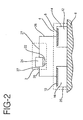
- the controller 2 has a power supply 22 and electronic control circuitry 24, as shown in FIG. 2.
- the controller is electrically coupled to the patch 4 using electronic interconnectors 26 and 27, such as a printed flexible circuit, metal foils, wires, tabs or electrically conductive adhesives.
- the power supply 22 in combination with the electrodes 8 and 10 and the patient's body 6 completes the iontophoretic circuit and generates an electric field across the body surface or skin on which the iontophoretic device is applied. The electric field causes the drug in the active reservoir 14 to be delivered into the body of the patient by iontophoresis.
- the lower surface of the reservoirs are placed in contact with the skin.
- the electrodes are positioned so that an ionic current path is established between the electrodes 8 and 10 through the reservoirs and the patient's skin 6. Electrodes 8 and 10 are placed in conductive contact with the gels 12 and 16, respectively.
- a direct current source may be connected to the electrodes 8 and 10 so that the active electrode has the same charge polarity as the ionic drug 12. When current is passed through the active electrode 8 to the return electrode 10 through the skin 6, the ionic drug 12 contained in the active reservoir 14 is delivered through the skin 6 and into the patient.
- FIG. 3 depicts a controller 2 that may be used as either a master controller, a slave controller, or as a multi-master controller, as explained below.
- the controller 2 may include, but is not limited to, a microprocessor 40, a digital-to-analog converter (DAC) 44, and a current control circuit 42.
- the microprocessor 40 sends a digital signal to the DAC 44, which converts the digital signal to an analog signal 50.
- This analog signal 50 controls the current control circuit 42 which ensures that the required amount of DC current is delivered to the patch 4 so that the correct amount of drug is delivered to the patient.
- the current control circuit 42 will produce the required DC output current irrespective of the varying impedance and/or capacitance of the load, including the patient's skin, the impedance of which normally varies from patient to patient and which may change as iontophoresis takes place.
- a sensor such as a current sense resistor 48
- the current passing through the current sense resistor 48 is the same current actually being delivered through the iontophoretic patch and the skin. If an amount of DC current actually delivered is less than or greater than the required DC current, the current control circuit 42 adjusts the DC current to the required level.
- the controller also includes a transmitter for transmitting information into the patient's skin through the patch 4.
- the transmitter comprises the modulator 43 and the current control circuit 42.
- the modulator 43 modulates an AC carrier with information from the microprocessor 40 resulting in a modulated carrier signal 51.
- This signal 51 is supplied to the current control circuit 42.
- the current control circuit 42 superposes the modulated carrier signal 51 with the DC current being delivered to the patch 4.
- the current flowing through the patch 4 therefore contains a DC component and an AC component.
- the DC component causes the drugs to be delivered into the patient's body via iontophoresis, as described above.
- the carrier frequency of the AC component of the current is greater than approximately 1000 Hz
- the AC component will be conducted by the patient's skin so that the signal will travel along the patient's skin.
- the modulated AC carrier signal can be received at all areas of the patient's body.
- This AC carrier signal does not, however, contribute to the delivery of drugs because the average value of the AC signal is zero.
- the voltage of the AC component applied to the patch is preferably between 50 and 500 mV.
- the controller also includes a receiver.
- the receiver comprises the demodulator 45.
- the receiver can receive the modulated AC carrier signals (transmitted by other controllers) from the patient's skin.
- the modulated AC carrier is demodulated by the demodulator 45, extracting the transmitted information. This information is digitized and sent to the microprocessor 40 where it is read. The microprocessor can then take appropriate controlling action, depending on the information that is received.
- controllers located at different sites on a patient's body can be used. These configurations include, but are not limited to, a master-slave arrangement and a multi-master arrangement. Other arrangements can be readily envisioned. Various methods of interfacing and coordinating the multiple controllers are well known to those skilled in the art of computer architecture and network design.
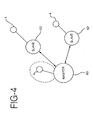
- FIG. 4 is a pictorial representation of a master-slave arrangement of controllers.
- the master controller unit 60 is located at a first area on the patient's skin.
- the slave units 62 are located at other areas on the patient's skin.
- Each of the slave units 62 has an iontophoretic patch 4 for delivering drugs to the patient. While FIG. 4 depicts one master unit and two slave units, any number of slave units can be used.
- a patch 4 controlled directly by the master controller 60 may also optionally be included.
- the master unit transmits commands to one or more of the slave units instructing the slave units to deliver drugs and, optionally, to control the drug dosage by controlling the amount of current to be generated by the slave units.
- the slave units have the capability of transmitting information back to the master unit, and the master unit has the capability of receiving this information.
- the embodiment can advantageously respond to changing conditions of the patient's body. For example, if an additional slave unit is affixed to the skin of the patient, the master unit 60 can recognize this condition, and instruct the slave unit to deliver drugs according to a desired pattern. Alternatively, if a slave unit 62 is removed from the patient's body, the master unit 60 can recognize this condition and adjust the operation of the remaining slave units accordingly.
- FIGS. 5 and 6 show the operation of a master and slave arrangement configuration for alternately delivering two drugs to a patient. This configuration uses one master unit and two slave units.
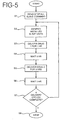
- FIG. 5 depicts the operation of the master unit or controller in the master-slave configuration.
- the master unit After the master unit is turned on, it sends a stop command that stops all the slaves from delivering drugs in step S1.
- the master unit interrogates all of the slave units to identify which slave units are attached to the body.
- the master unit identifies a first controller for delivering a first drug and a second controller for delivering a second drug. Further, in this example, the first drug is delivered for one hour, followed by a one hour period during which no drug is delivered. Then, the second drug is delivered for three hours, followed by another hour during which no drug is delivered. This cycle is to be repeated four times, and then drug delivery is stopped.
- the master unit After the initializing steps S1 and S2, the master unit starts the desired sequence of drug delivery in step S3 by sending a command to the first slave unit to start delivering drugs. The master unit then keeps track of time until one hour has passed, at which time it sends a command to the first slave unit instructing it to stop delivering drugs.
- step S4 the master unit keeps track of time until one hour has passed.
- step S5 the master unit commands the second slave unit to start delivering its drug. The master unit keeps track of time until three hours have passed, at which time it sends a command to stop the second slave unit.
- step S6 the master unit waits for one hour to pass with no drug delivery. This completes a full cycle of drug delivery.
- the master unit keeps track of the number of cycles of drug delivery that have been completed.
- step S7 the master unit determines whether four drug delivery cycles have been completed. If four delivery cycles have not been completed, the master unit returns to the beginning of the routine for another cycle of drug delivery. When this cycle is complete, control returns to step S7. This continues until the master unit determines, in step S7, that four drug delivery cycles have been completed. When four delivery cycles have been completed, the master unit stops in step S8 and no further delivery of drugs occurs.
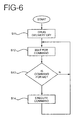
- FIG. 6 depicts the control sequence of the slave unit in the master-slave configuration.
- the slave unit When the slave unit is first turned on or otherwise activated, it turns off the delivery of drugs in step S11, and then proceeds to step S12 to wait for a command to arrive from the master unit.
- Some commands may be intended for the slave unit in question and other commands may be intended for other slave units.
- the slave unit examines the command in step S13 and determines if the command is intended for itself. If the command is not intended for that particular slave unit in S13, the slave unit will not execute the command and will return to step S12 to wait for another command. If it is determined, however, that the command is intended for the particular slave unit in step S13, the slave unit executes the received command in step S14.
- the command from the master unit may simply instruct the slave unit to start or stop delivering drugs, with the dosage being preset for a given slave unit.
- the command from the master unit may contain information for setting the slave unit to deliver a desired dosage of drugs by appropriately setting the level of DC current.
- the slave unit may also be programmed to acknowledge certain commands received from the master unit.
- the slave unit receives this type of command, it transmits an acknowledgment signal back to the master unit.
- This acknowledgment signal could be a simple present/absent indication. Alternatively, it could report the status of the slave unit, including, for example, the amount of drugs remaining in the slave unit, the status of the slave unit battery, and other parameters.
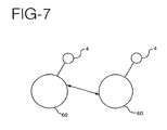
- FIG. 7 depicts a multi-master configuration of units or controllers. While FIG. 7 depicts two controllers 60, any number of controllers may be used. Each controller 60 has an associated patch 4 for delivery drugs to the patient. This configuration will be described in the context of delivering the same drug from multiple controllers, where the dosage of the drug is to be maintained constant regardless of the number of patches installed on the patient's body. In this configuration, when one patch is installed on the patient's body the dosage from each patch should be an amount "X"; when two patches are installed, the dosage from each patch should be X divided by 2; when three patches are installed, the dosage from each patch should be X divided by 3, and so on.
- This configuration could be used, for example, when a particular drug must be delivered constantly and where the dosage must be controlled with high accuracy. If a single controller were to be used in this application, a failure in that controller could interrupt the delivery of the drug. If independent controllers were used instead, a failure in any one controller might result in an incorrect drug dosage. By using a plurality of identical controllers that communicate with one another, these drawbacks can be eliminated and the desired drug dosage can be delivered.
- each of the multi-master units or controllers is programmed to adjust its drug output depending on how many other controllers are delivering drugs.
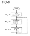
- a given controller When a given controller is first turned on, it stops the delivery of drugs in step S20.
- the controller sends and receives signals through the patient's body to determine a number of controllers (N) that are already delivering drugs to the patient.
- the controller sets its dosage to the desired total dosage (D) divided by N+1.
- the other controllers in the system will recognize that the new controller has been added when they execute their own step S21, and reduce their dosage from D ⁇ N to D ⁇ (N+1) in step S22.
- the final result is N+1 controllers each delivering a dosage of D ⁇ (N+1), resulting in a total dosage of D.
- the invention may take forms other than those specifically described.
- the signal may be capacitively coupled into the patients' skin.
- the master and slave units may be interconnected by wires and the like.
- the master is a transmit-only device and each of the slaves is a receive-only device.
- the demodulator 45 is not required in the master unit, and the modulator 43 is not required in each of the slave units.
Landscapes
- Health & Medical Sciences (AREA)
- Engineering & Computer Science (AREA)
- General Health & Medical Sciences (AREA)
- Veterinary Medicine (AREA)
- Biomedical Technology (AREA)
- Public Health (AREA)
- Life Sciences & Earth Sciences (AREA)
- Animal Behavior & Ethology (AREA)
- Nuclear Medicine, Radiotherapy & Molecular Imaging (AREA)
- Radiology & Medical Imaging (AREA)
- Bioinformatics & Cheminformatics (AREA)
- Anesthesiology (AREA)
- Heart & Thoracic Surgery (AREA)
- Hematology (AREA)
- Vascular Medicine (AREA)
- Chemical & Material Sciences (AREA)
- Medicinal Chemistry (AREA)
- Electrotherapy Devices (AREA)
Claims (6)
- Appareil permettant d'administrer des médicaments à un patient, comprenant :dans lequel la première unité comprend de plus un premier contrôleur (2) permettant d'amener le premier dispositif d'administration de médicaments (4) à administrer un premier médicament (12) ;une première unité comprenant un premier dispositif d'administration de médicaments (4), ladite première unité pouvant être apposée sur une première zone sur la peau du patient (6) ; etune deuxième unité comprenant un deuxième dispositif d'administration de médicaments (4), ladite deuxième unité pouvant être apposée sur une deuxième zone sur la peau du patient (6) ;
caractérisé en ce que
la deuxième unité comprend de plus un deuxième contrôleur (2) permettant d'amener le deuxième dispositif d'administration de médicaments (4) à administrer un deuxième médicament (12) ; et
ledit deuxième contrôleur (2) est capable de communiquer sélectivement avec ledit premier contrôleur (2) par l'intermédiaire de signaux qui se déplacent entre ledit premier contrôleur (2) et ledit deuxième contrôleur (2). - Appareil selon la revendication 1, dans lequel
chaque contrôleur (2) comprend un émetteur pour émettre des signaux, l'émetteur comprenant un modulateur (43) pour moduler une porteuse en courant alternatif avec des commandes à émettre, chaque contrôleur (2) comprend un récepteur pour recevoir des signaux, le récepteur comprenant un démodulateur (45) pour extraire les commandes de la porteuse modulée, et
chaque dispositif d'administration de médicaments (4) comprend un timbre ionophorétique. - Appareil selon la revendication 2, dans lequel les commandes sont couplées dans le patient par des moyens sélectionnés parmi (a) la superposition du courant continu passant par le timbre à la porteuse en courant alternatif modulée (51) et (b) le couplage capacitif de la porteuse en courant alternatif modulée (51) dans la peau du patient.
- Appareil selon la revendication 2, dans lequel la fréquence de la porteuse en courant alternatif (51) se situe dans une plage sélectionnée parmi (a) une radiofréquence ou inférieure et (b) une fréquence supérieure à environ 1000 Hz.
- Appareil selon la revendication 2, dans lequel le signal est conduit le long de la peau du patient (6).
- Appareil selon la revendication 2, comprenant en outre une troisième unité comprenant un troisième dispositif d'administration de médicaments (4) et un troisième contrôleur (2) pour amener le troisième dispositif d'administration de médicaments pour délivrer un troisième médicament (12), ladite troisième unité pouvant être apposée sur une troisième zone sur la peau du patient (6), ledit troisième contrôleur communiquant sélectivement avec ledit premier contrôleur (2) et ledit deuxième contrôleur (2) par l'intermédiaire de signaux qui se déplacent entre lesdits contrôleurs.
Applications Claiming Priority (2)
| Application Number | Priority Date | Filing Date | Title |
|---|---|---|---|
| US921915 | 1986-10-20 | ||
| US08/921,915 US5899876A (en) | 1997-08-27 | 1997-08-27 | Multiple site drug delivery system |
Publications (3)
| Publication Number | Publication Date |
|---|---|
| EP0906767A2 EP0906767A2 (fr) | 1999-04-07 |
| EP0906767A3 EP0906767A3 (fr) | 2000-01-05 |
| EP0906767B1 true EP0906767B1 (fr) | 2005-03-30 |
Family
ID=25446177
Family Applications (1)
| Application Number | Title | Priority Date | Filing Date |
|---|---|---|---|
| EP98306884A Expired - Lifetime EP0906767B1 (fr) | 1997-08-27 | 1998-08-27 | Système d'administration de médicament en plusieurs endroits du corps |
Country Status (3)
| Country | Link |
|---|---|
| US (1) | US5899876A (fr) |
| EP (1) | EP0906767B1 (fr) |
| DE (1) | DE69829533T2 (fr) |
Families Citing this family (107)
| Publication number | Priority date | Publication date | Assignee | Title |
|---|---|---|---|---|
| US6956032B1 (en) | 1986-04-18 | 2005-10-18 | Carnegie Mellon University | Cyanine dyes as labeling reagents for detection of biological and other materials by luminescence methods |
| US6148231A (en) * | 1998-09-15 | 2000-11-14 | Biophoretic Therapeutic Systems, Llc | Iontophoretic drug delivery electrodes and method |
| US6792306B2 (en) * | 2000-03-10 | 2004-09-14 | Biophoretic Therapeutic Systems, Llc | Finger-mounted electrokinetic delivery system for self-administration of medicaments and methods therefor |
| US7127285B2 (en) * | 1999-03-12 | 2006-10-24 | Transport Pharmaceuticals Inc. | Systems and methods for electrokinetic delivery of a substance |
| US6477410B1 (en) * | 2000-05-31 | 2002-11-05 | Biophoretic Therapeutic Systems, Llc | Electrokinetic delivery of medicaments |
| US6553253B1 (en) * | 1999-03-12 | 2003-04-22 | Biophoretic Therapeutic Systems, Llc | Method and system for electrokinetic delivery of a substance |
| US6385488B1 (en) | 1999-05-20 | 2002-05-07 | Vyteris, Inc. | Circuits for increasing the reliability of an iontophoretic system |
| US6835184B1 (en) | 1999-09-24 | 2004-12-28 | Becton, Dickinson And Company | Method and device for abrading skin |
| CA2400074A1 (fr) | 2000-02-18 | 2001-08-23 | William I. Higuchi | Procedes d'extraction de substances par utilisation de courant alternatif |
| EP1259285A1 (fr) | 2000-02-18 | 2002-11-27 | University of Utah | Procede d'apport d'agents au moyen de courant alternatif |
| US7137975B2 (en) * | 2001-02-13 | 2006-11-21 | Aciont, Inc. | Method for increasing the battery life of an alternating current iontophoresis device using a barrier-modifying agent |
| US7160258B2 (en) * | 2001-06-26 | 2007-01-09 | Entrack, Inc. | Capsule and method for treating or diagnosing the intestinal tract |
| EP1402920A1 (fr) * | 2002-09-30 | 2004-03-31 | Faco S.A. | Dispositif de traitement corporel électrique, en particulier dispositif d'électrostimulation ou d'ionophorese |
| DE102005022428A1 (de) | 2005-05-14 | 2006-11-16 | B. Braun Medizinelektronik Gmbh & Co. Kg | Verfahren und Vorrichtung zur Steuerung einer Mehrzahl von Infusionspumpen |
| US8391990B2 (en) | 2005-05-18 | 2013-03-05 | Cardiac Pacemakers, Inc. | Modular antitachyarrhythmia therapy system |
| EP2117578B1 (fr) | 2007-01-22 | 2015-04-22 | OrthoTrophix, Inc. | Composition peptidique et procédé permettant de favoriser la formation de cartilage |
| US8197844B2 (en) | 2007-06-08 | 2012-06-12 | Activatek, Inc. | Active electrode for transdermal medicament administration |
| US8862223B2 (en) | 2008-01-18 | 2014-10-14 | Activatek, Inc. | Active transdermal medicament patch and circuit board for same |
| US20090259176A1 (en) * | 2008-04-09 | 2009-10-15 | Los Gatos Research, Inc. | Transdermal patch system |
| US20110172293A1 (en) | 2008-07-08 | 2011-07-14 | Fish Jason E | Methods and Compositions for Modulating Angiogenesis |
| EP2957319A4 (fr) * | 2013-02-18 | 2016-10-12 | Terumo Corp | Dispositif ainsi que système d'administration de médicament, et procédé de commande de ceux-ci |
| WO2015106015A1 (fr) | 2014-01-10 | 2015-07-16 | Cardiac Pacemakers, Inc. | Systèmes et procédés de détection d'arythmies cardiaques |
| ES2661718T3 (es) | 2014-01-10 | 2018-04-03 | Cardiac Pacemakers, Inc. | Métodos y sistemas para mejorar la comunicación entre dispositivos médicos |
| US9757570B2 (en) | 2014-08-06 | 2017-09-12 | Cardiac Pacemakers, Inc. | Communications in a medical device system |
| US9694189B2 (en) | 2014-08-06 | 2017-07-04 | Cardiac Pacemakers, Inc. | Method and apparatus for communicating between medical devices |
| US9808631B2 (en) | 2014-08-06 | 2017-11-07 | Cardiac Pacemakers, Inc. | Communication between a plurality of medical devices using time delays between communication pulses to distinguish between symbols |
| CN107073275B (zh) | 2014-08-28 | 2020-09-01 | 心脏起搏器股份公司 | 具有触发的消隐周期的医疗设备 |
| ES2713231T3 (es) | 2015-02-06 | 2019-05-20 | Cardiac Pacemakers Inc | Sistemas para el suministro seguro de una terapia de estimulación eléctrica |
| JP6510660B2 (ja) | 2015-02-06 | 2019-05-08 | カーディアック ペースメイカーズ, インコーポレイテッド | 心不整脈を治療するためのシステムおよび方法 |
| WO2016130477A2 (fr) | 2015-02-09 | 2016-08-18 | Cardiac Pacemakers, Inc. | Dispositif médical implantable comportant une étiquette d'identification radio-opaque |
| EP3265172B1 (fr) | 2015-03-04 | 2018-12-19 | Cardiac Pacemakers, Inc. | Systèmes de traitement d'arythmies cardiaques |
| US10050700B2 (en) | 2015-03-18 | 2018-08-14 | Cardiac Pacemakers, Inc. | Communications in a medical device system with temporal optimization |
| CN107427222B (zh) | 2015-03-18 | 2021-02-09 | 心脏起搏器股份公司 | 使用链路质量评估的医疗设备系统中的通信 |
| WO2017031347A1 (fr) | 2015-08-20 | 2017-02-23 | Cardiac Pacemakers, Inc. | Systèmes et procédés de communication entre des dispositifs médicaux |
| EP3337558B1 (fr) | 2015-08-20 | 2025-05-28 | Cardiac Pacemakers, Inc. | Procédés de communication entre des dispositifs médicaux |
| US9956414B2 (en) | 2015-08-27 | 2018-05-01 | Cardiac Pacemakers, Inc. | Temporal configuration of a motion sensor in an implantable medical device |
| US9968787B2 (en) | 2015-08-27 | 2018-05-15 | Cardiac Pacemakers, Inc. | Spatial configuration of a motion sensor in an implantable medical device |
| US10159842B2 (en) | 2015-08-28 | 2018-12-25 | Cardiac Pacemakers, Inc. | System and method for detecting tamponade |
| CN108136189B (zh) | 2015-08-28 | 2021-10-15 | 心脏起搏器股份公司 | 用于行为响应信号检测和治疗递送的系统 |
| US10226631B2 (en) | 2015-08-28 | 2019-03-12 | Cardiac Pacemakers, Inc. | Systems and methods for infarct detection |
| US10092760B2 (en) | 2015-09-11 | 2018-10-09 | Cardiac Pacemakers, Inc. | Arrhythmia detection and confirmation |
| US10065041B2 (en) | 2015-10-08 | 2018-09-04 | Cardiac Pacemakers, Inc. | Devices and methods for adjusting pacing rates in an implantable medical device |
| WO2017106693A1 (fr) | 2015-12-17 | 2017-06-22 | Cardiac Pacemakers, Inc. | Communication menée dans un système de dispositif médical |
| US10905886B2 (en) | 2015-12-28 | 2021-02-02 | Cardiac Pacemakers, Inc. | Implantable medical device for deployment across the atrioventricular septum |
| US10583303B2 (en) | 2016-01-19 | 2020-03-10 | Cardiac Pacemakers, Inc. | Devices and methods for wirelessly recharging a rechargeable battery of an implantable medical device |
| US10350423B2 (en) | 2016-02-04 | 2019-07-16 | Cardiac Pacemakers, Inc. | Delivery system with force sensor for leadless cardiac device |
| WO2017173275A1 (fr) | 2016-03-31 | 2017-10-05 | Cardiac Pacemakers, Inc. | Dispositif médical implantable à batterie rechargeable |
| US10328272B2 (en) | 2016-05-10 | 2019-06-25 | Cardiac Pacemakers, Inc. | Retrievability for implantable medical devices |
| US10668294B2 (en) | 2016-05-10 | 2020-06-02 | Cardiac Pacemakers, Inc. | Leadless cardiac pacemaker configured for over the wire delivery |
| EP3474945B1 (fr) | 2016-06-27 | 2022-12-28 | Cardiac Pacemakers, Inc. | Système de thérapie cardiaque utilisant des ondes p détectées de manière sous-cutanée pour la gestion de la stimulation de resynchronisation |
| US11207527B2 (en) | 2016-07-06 | 2021-12-28 | Cardiac Pacemakers, Inc. | Method and system for determining an atrial contraction timing fiducial in a leadless cardiac pacemaker system |
| US10426962B2 (en) | 2016-07-07 | 2019-10-01 | Cardiac Pacemakers, Inc. | Leadless pacemaker using pressure measurements for pacing capture verification |
| EP3487579B1 (fr) | 2016-07-20 | 2020-11-25 | Cardiac Pacemakers, Inc. | Système de repère de synchronisation de contraction auriculaire dans un stimulateur cardiaque sans fil. |
| EP3500342B1 (fr) | 2016-08-19 | 2020-05-13 | Cardiac Pacemakers, Inc. | Dispositif médical implantable trans-septal |
| US10780278B2 (en) | 2016-08-24 | 2020-09-22 | Cardiac Pacemakers, Inc. | Integrated multi-device cardiac resynchronization therapy using P-wave to pace timing |
| EP3503970B1 (fr) | 2016-08-24 | 2023-01-04 | Cardiac Pacemakers, Inc. | Resynchronisation cardiaque utilisant l'encouragement de la fusion pour la gestion de la synchronisation |
| US10758737B2 (en) | 2016-09-21 | 2020-09-01 | Cardiac Pacemakers, Inc. | Using sensor data from an intracardially implanted medical device to influence operation of an extracardially implantable cardioverter |
| US10905889B2 (en) | 2016-09-21 | 2021-02-02 | Cardiac Pacemakers, Inc. | Leadless stimulation device with a housing that houses internal components of the leadless stimulation device and functions as the battery case and a terminal of an internal battery |
| US10994145B2 (en) | 2016-09-21 | 2021-05-04 | Cardiac Pacemakers, Inc. | Implantable cardiac monitor |
| US10413733B2 (en) | 2016-10-27 | 2019-09-17 | Cardiac Pacemakers, Inc. | Implantable medical device with gyroscope |
| US10758724B2 (en) | 2016-10-27 | 2020-09-01 | Cardiac Pacemakers, Inc. | Implantable medical device delivery system with integrated sensor |
| WO2018081133A1 (fr) | 2016-10-27 | 2018-05-03 | Cardiac Pacemakers, Inc. | Dispositif médical implantable présentant un canal d'écoute à réglage de rendement |
| WO2018081275A1 (fr) | 2016-10-27 | 2018-05-03 | Cardiac Pacemakers, Inc. | Thérapie de resynchronisation cardiaque à dispositifs multiples avec des améliorations de synchronisation |
| CN109890458B (zh) | 2016-10-27 | 2023-08-11 | 心脏起搏器股份公司 | 具有压力传感器的可植入医疗设备 |
| US10434314B2 (en) | 2016-10-27 | 2019-10-08 | Cardiac Pacemakers, Inc. | Use of a separate device in managing the pace pulse energy of a cardiac pacemaker |
| EP3532157B1 (fr) | 2016-10-31 | 2020-08-26 | Cardiac Pacemakers, Inc. | Systèmes de stimulation de niveau d'activité |
| JP6843235B2 (ja) | 2016-10-31 | 2021-03-17 | カーディアック ペースメイカーズ, インコーポレイテッド | 活動レベル・ペーシングのためのシステムおよび方法 |
| US10583301B2 (en) | 2016-11-08 | 2020-03-10 | Cardiac Pacemakers, Inc. | Implantable medical device for atrial deployment |
| US10632313B2 (en) | 2016-11-09 | 2020-04-28 | Cardiac Pacemakers, Inc. | Systems, devices, and methods for setting cardiac pacing pulse parameters for a cardiac pacing device |
| US10881869B2 (en) | 2016-11-21 | 2021-01-05 | Cardiac Pacemakers, Inc. | Wireless re-charge of an implantable medical device |
| US10639486B2 (en) | 2016-11-21 | 2020-05-05 | Cardiac Pacemakers, Inc. | Implantable medical device with recharge coil |
| CN109963618B (zh) | 2016-11-21 | 2023-07-04 | 心脏起搏器股份公司 | 具有多模式通信的无引线心脏起搏器 |
| US10894163B2 (en) | 2016-11-21 | 2021-01-19 | Cardiac Pacemakers, Inc. | LCP based predictive timing for cardiac resynchronization |
| EP3541472B1 (fr) | 2016-11-21 | 2023-06-07 | Cardiac Pacemakers, Inc. | Dispositif médical implantable comportant un boîtier magnétiquement perméable et une bobine inductive placée autour du boîtier |
| US11207532B2 (en) | 2017-01-04 | 2021-12-28 | Cardiac Pacemakers, Inc. | Dynamic sensing updates using postural input in a multiple device cardiac rhythm management system |
| CN110225778B (zh) | 2017-01-26 | 2023-06-13 | 心脏起搏器股份公司 | 具有冗余消息传输的体内设备通信 |
| EP3573709A1 (fr) | 2017-01-26 | 2019-12-04 | Cardiac Pacemakers, Inc. | Dispositif sans fil présentant des composants surmoulés |
| WO2018140797A1 (fr) | 2017-01-26 | 2018-08-02 | Cardiac Pacemakers, Inc. | Dispositif implantable sans fil à fixation amovible |
| WO2018187121A1 (fr) | 2017-04-03 | 2018-10-11 | Cardiac Pacemakers, Inc. | Stimulateur cardiaque à énergie d'impulsion de stimulation ajustable sur la base d'une fréquence cardiaque détectée |
| US10905872B2 (en) | 2017-04-03 | 2021-02-02 | Cardiac Pacemakers, Inc. | Implantable medical device with a movable electrode biased toward an extended position |
| WO2019036568A1 (fr) | 2017-08-18 | 2019-02-21 | Cardiac Pacemakers, Inc. | Dispositif médical implantable comprenant un concentrateur de flux et une bobine de réception disposée autour du concentrateur de flux |
| EP3668592B1 (fr) | 2017-08-18 | 2021-11-17 | Cardiac Pacemakers, Inc. | Dispositif médical implantable avec capteur de pression |
| WO2019060302A1 (fr) | 2017-09-20 | 2019-03-28 | Cardiac Pacemakers, Inc. | Dispositif médical implantable avec modes de fonctionnement multiples |
| US11185703B2 (en) | 2017-11-07 | 2021-11-30 | Cardiac Pacemakers, Inc. | Leadless cardiac pacemaker for bundle of his pacing |
| EP3717059B1 (fr) | 2017-12-01 | 2024-11-20 | Cardiac Pacemakers, Inc. | Systèmes pour détecter des repères de synchronisation de contraction auriculaire dans une fenêtre de recherche à partir d'un stimulateur cardiaque sans fil implanté de manière ventriculaire |
| WO2019108482A1 (fr) | 2017-12-01 | 2019-06-06 | Cardiac Pacemakers, Inc. | Procédés et systèmes pour détecter des repères de synchronisation de contraction auriculaire et pour déterminer un intervalle cardiaque à partir d'un stimulateur cardiaque sans fil implanté de manière ventriculaire |
| US11260216B2 (en) | 2017-12-01 | 2022-03-01 | Cardiac Pacemakers, Inc. | Methods and systems for detecting atrial contraction timing fiducials during ventricular filling from a ventricularly implanted leadless cardiac pacemaker |
| US11813463B2 (en) | 2017-12-01 | 2023-11-14 | Cardiac Pacemakers, Inc. | Leadless cardiac pacemaker with reversionary behavior |
| EP3735293B1 (fr) | 2018-01-04 | 2022-03-09 | Cardiac Pacemakers, Inc. | Stimulation double chambre sans communication battement à battement |
| US11529523B2 (en) | 2018-01-04 | 2022-12-20 | Cardiac Pacemakers, Inc. | Handheld bridge device for providing a communication bridge between an implanted medical device and a smartphone |
| US11058880B2 (en) | 2018-03-23 | 2021-07-13 | Medtronic, Inc. | VFA cardiac therapy for tachycardia |
| JP2021518192A (ja) | 2018-03-23 | 2021-08-02 | メドトロニック,インコーポレイテッド | VfA心臓再同期治療 |
| WO2019183507A1 (fr) | 2018-03-23 | 2019-09-26 | Medtronic, Inc. | Thérapie cardiaque du ventricule vers l'atrium (vfa) synchrone atrioventriculaire (av) |
| US11235161B2 (en) | 2018-09-26 | 2022-02-01 | Medtronic, Inc. | Capture in ventricle-from-atrium cardiac therapy |
| US11951313B2 (en) | 2018-11-17 | 2024-04-09 | Medtronic, Inc. | VFA delivery systems and methods |
| US12296177B2 (en) | 2018-12-21 | 2025-05-13 | Medtronic, Inc. | Delivery systems and methods for left ventricular pacing |
| CN109464742B (zh) * | 2018-12-29 | 2024-08-09 | 上海安翰医疗技术有限公司 | 胃肠道定位开关及其制作方法及消化道定点药物释放胶囊 |
| US11679265B2 (en) | 2019-02-14 | 2023-06-20 | Medtronic, Inc. | Lead-in-lead systems and methods for cardiac therapy |
| US11697025B2 (en) | 2019-03-29 | 2023-07-11 | Medtronic, Inc. | Cardiac conduction system capture |
| US11213676B2 (en) | 2019-04-01 | 2022-01-04 | Medtronic, Inc. | Delivery systems for VfA cardiac therapy |
| US11712188B2 (en) | 2019-05-07 | 2023-08-01 | Medtronic, Inc. | Posterior left bundle branch engagement |
| US11305127B2 (en) | 2019-08-26 | 2022-04-19 | Medtronic Inc. | VfA delivery and implant region detection |
| US11813466B2 (en) | 2020-01-27 | 2023-11-14 | Medtronic, Inc. | Atrioventricular nodal stimulation |
| US12543992B2 (en) | 2020-03-30 | 2026-02-10 | Medtronic, Inc. | Pacing efficacy determination using a representative morphology of external cardiac signals |
| US11911168B2 (en) | 2020-04-03 | 2024-02-27 | Medtronic, Inc. | Cardiac conduction system therapy benefit determination |
| US11813464B2 (en) | 2020-07-31 | 2023-11-14 | Medtronic, Inc. | Cardiac conduction system evaluation |
| US12465770B2 (en) | 2020-07-31 | 2025-11-11 | Medtronic, Inc. | Coronary sinus conduction system pacing and delivery |
Family Cites Families (9)
| Publication number | Priority date | Publication date | Assignee | Title |
|---|---|---|---|---|
| US4856188A (en) * | 1984-10-12 | 1989-08-15 | Drug Delivery Systems Inc. | Method for making disposable and/or replenishable transdermal drug applicators |
| DE3831809A1 (de) * | 1988-09-19 | 1990-03-22 | Funke Hermann | Zur mindestens teilweisen implantation im lebenden koerper bestimmtes geraet |
| ES2129035T3 (es) * | 1989-05-10 | 1999-06-01 | Drug Delivery Systems Inc | Aplicador de medicina transdermal electrico de multiples señales. |
| US5135478A (en) * | 1989-05-10 | 1992-08-04 | Drug Delivery Systems Inc. | Multi-signal electrical transdermal drug applicator |
| IT1244030B (it) * | 1989-12-21 | 1994-06-28 | Elan Corp Plc | Dispostitivo in due parti per la somministrazione controllata di un ingrediente |
| WO1991015261A1 (fr) * | 1990-03-30 | 1991-10-17 | Medtronic, Inc. | Dispositif d'administration de medicaments par electrotransport regulee par l'activite |
| US5254081A (en) * | 1991-02-01 | 1993-10-19 | Empi, Inc. | Multiple site drug iontophoresis electronic device and method |
| US5421817A (en) * | 1991-05-21 | 1995-06-06 | E.P., Inc. | Non-intrusive analgesic neuroaugmentive and iontophoretic delivery apparatus and management system |
| US5551953A (en) * | 1994-10-31 | 1996-09-03 | Alza Corporation | Electrotransport system with remote telemetry link |
-
1997
- 1997-08-27 US US08/921,915 patent/US5899876A/en not_active Expired - Fee Related
-
1998
- 1998-08-27 DE DE69829533T patent/DE69829533T2/de not_active Expired - Fee Related
- 1998-08-27 EP EP98306884A patent/EP0906767B1/fr not_active Expired - Lifetime
Also Published As
| Publication number | Publication date |
|---|---|
| US5899876A (en) | 1999-05-04 |
| DE69829533T2 (de) | 2006-03-30 |
| EP0906767A2 (fr) | 1999-04-07 |
| EP0906767A3 (fr) | 2000-01-05 |
| DE69829533D1 (de) | 2005-05-04 |
Similar Documents
| Publication | Publication Date | Title |
|---|---|---|
| EP0906767B1 (fr) | Système d'administration de médicament en plusieurs endroits du corps | |
| EP3740278B1 (fr) | Appareil de stimulation électrique | |
| US6381496B1 (en) | Parameter context switching for an implanted device | |
| US6317630B1 (en) | Drug delivery device | |
| US6516227B1 (en) | Rechargeable spinal cord stimulator system | |
| EP2002861B1 (fr) | Système de stimulateur de moelle épinière rechargeable | |
| JP3916660B2 (ja) | 再使用可能コントローラを有する電子運搬装置の電力節約装置 | |
| US4456012A (en) | Iontophoretic and electrical tissue stimulation device | |
| US20020193844A1 (en) | Combination electrode-battery assembly for a miniature wireless transcutaneous electrical neuro or muscular-stimulation unit | |
| US5830175A (en) | Iontophoretic drug delivery system, including disposable patch | |
| EP0789603B1 (fr) | Systeme d'electrotransport avec liaison de telemesure a distance | |
| WO2007134288A2 (fr) | Combinaison électrode-batterie et assemblage de programmation pour une unité de neurostimulation ou de stimulation musculaire électrique transcutanée miniature sans fil | |
| AU2000263762A1 (en) | Rechargeable spinal cord stimulator system | |
| AU714537B2 (en) | Electrotransport device having reusable controller | |
| US5983133A (en) | Iontophoresis system with voltage step-up circuit | |
| CN216295009U (zh) | 植入式神经刺激器 | |
| WO1996010441A9 (fr) | Systeme d'administration d'un medicament par ionophorese, comprenant un timbre a usage unique et un dispositif de commande amovible, reutilisable | |
| EP0783345A1 (fr) | Systeme d'administration d'un medicament par ionophorese, comprenant un timbre a usage unique et un dispositif de commande amovible, reutilisable |
Legal Events
| Date | Code | Title | Description |
|---|---|---|---|
| PUAI | Public reference made under article 153(3) epc to a published international application that has entered the european phase |
Free format text: ORIGINAL CODE: 0009012 |
|
| AK | Designated contracting states |
Kind code of ref document: A2 Designated state(s): DE FR GB |
|
| AX | Request for extension of the european patent |
Free format text: AL;LT;LV;MK;RO;SI |
|
| PUAL | Search report despatched |
Free format text: ORIGINAL CODE: 0009013 |
|
| AK | Designated contracting states |
Kind code of ref document: A3 Designated state(s): AT BE CH CY DE DK ES FI FR GB GR IE IT LI LU MC NL PT SE |
|
| AX | Request for extension of the european patent |
Free format text: AL;LT;LV;MK;RO;SI |
|
| 17P | Request for examination filed |
Effective date: 20000628 |
|
| AKX | Designation fees paid |
Free format text: DE FR GB |
|
| RAP1 | Party data changed (applicant data changed or rights of an application transferred) |
Owner name: VYTERIS, INC. |
|
| 17Q | First examination report despatched |
Effective date: 20030429 |
|
| GRAP | Despatch of communication of intention to grant a patent |
Free format text: ORIGINAL CODE: EPIDOSNIGR1 |
|
| GRAS | Grant fee paid |
Free format text: ORIGINAL CODE: EPIDOSNIGR3 |
|
| GRAA | (expected) grant |
Free format text: ORIGINAL CODE: 0009210 |
|
| GRAL | Information related to payment of fee for publishing/printing deleted |
Free format text: ORIGINAL CODE: EPIDOSDIGR3 |
|
| GRAS | Grant fee paid |
Free format text: ORIGINAL CODE: EPIDOSNIGR3 |
|
| AK | Designated contracting states |
Kind code of ref document: B1 Designated state(s): DE FR GB |
|
| REG | Reference to a national code |
Ref country code: GB Ref legal event code: FG4D |
|
| REF | Corresponds to: |
Ref document number: 69829533 Country of ref document: DE Date of ref document: 20050504 Kind code of ref document: P |
|
| PLBE | No opposition filed within time limit |
Free format text: ORIGINAL CODE: 0009261 |
|
| STAA | Information on the status of an ep patent application or granted ep patent |
Free format text: STATUS: NO OPPOSITION FILED WITHIN TIME LIMIT |
|
| ET | Fr: translation filed | ||
| 26N | No opposition filed |
Effective date: 20060102 |
|
| PGFP | Annual fee paid to national office [announced via postgrant information from national office to epo] |
Ref country code: GB Payment date: 20070830 Year of fee payment: 10 |
|
| PGFP | Annual fee paid to national office [announced via postgrant information from national office to epo] |
Ref country code: DE Payment date: 20071001 Year of fee payment: 10 |
|
| PGFP | Annual fee paid to national office [announced via postgrant information from national office to epo] |
Ref country code: FR Payment date: 20070817 Year of fee payment: 10 |
|
| GBPC | Gb: european patent ceased through non-payment of renewal fee |
Effective date: 20080827 |
|
| REG | Reference to a national code |
Ref country code: FR Ref legal event code: ST Effective date: 20090430 |
|
| PG25 | Lapsed in a contracting state [announced via postgrant information from national office to epo] |
Ref country code: FR Free format text: LAPSE BECAUSE OF NON-PAYMENT OF DUE FEES Effective date: 20080901 Ref country code: DE Free format text: LAPSE BECAUSE OF NON-PAYMENT OF DUE FEES Effective date: 20090303 |
|
| PG25 | Lapsed in a contracting state [announced via postgrant information from national office to epo] |
Ref country code: GB Free format text: LAPSE BECAUSE OF NON-PAYMENT OF DUE FEES Effective date: 20080827 |