EP0906744A1 - Completely automatic waterless closet - Google Patents
Completely automatic waterless closet Download PDFInfo
- Publication number
- EP0906744A1 EP0906744A1 EP96910897A EP96910897A EP0906744A1 EP 0906744 A1 EP0906744 A1 EP 0906744A1 EP 96910897 A EP96910897 A EP 96910897A EP 96910897 A EP96910897 A EP 96910897A EP 0906744 A1 EP0906744 A1 EP 0906744A1
- Authority
- EP
- European Patent Office
- Prior art keywords
- pulling
- case body
- open
- crank
- doors
- Prior art date
- Legal status (The legal status is an assumption and is not a legal conclusion. Google has not performed a legal analysis and makes no representation as to the accuracy of the status listed.)
- Granted
Links
Images


Classifications
-
- A—HUMAN NECESSITIES
- A47—FURNITURE; DOMESTIC ARTICLES OR APPLIANCES; COFFEE MILLS; SPICE MILLS; SUCTION CLEANERS IN GENERAL
- A47K—SANITARY EQUIPMENT NOT OTHERWISE PROVIDED FOR; TOILET ACCESSORIES
- A47K11/00—Closets without flushing; Urinals without flushing; Chamber pots; Chairs with toilet conveniences or specially adapted for use with toilets
- A47K11/02—Dry closets, e.g. incinerator closets
- A47K11/026—Dry closets, e.g. incinerator closets with continuous tubular film for receiving faeces
-
- A—HUMAN NECESSITIES
- A47—FURNITURE; DOMESTIC ARTICLES OR APPLIANCES; COFFEE MILLS; SPICE MILLS; SUCTION CLEANERS IN GENERAL
- A47K—SANITARY EQUIPMENT NOT OTHERWISE PROVIDED FOR; TOILET ACCESSORIES
- A47K11/00—Closets without flushing; Urinals without flushing; Chamber pots; Chairs with toilet conveniences or specially adapted for use with toilets
- A47K11/02—Dry closets, e.g. incinerator closets
-
- Y—GENERAL TAGGING OF NEW TECHNOLOGICAL DEVELOPMENTS; GENERAL TAGGING OF CROSS-SECTIONAL TECHNOLOGIES SPANNING OVER SEVERAL SECTIONS OF THE IPC; TECHNICAL SUBJECTS COVERED BY FORMER USPC CROSS-REFERENCE ART COLLECTIONS [XRACs] AND DIGESTS
- Y02—TECHNOLOGIES OR APPLICATIONS FOR MITIGATION OR ADAPTATION AGAINST CLIMATE CHANGE
- Y02A—TECHNOLOGIES FOR ADAPTATION TO CLIMATE CHANGE
- Y02A50/00—TECHNOLOGIES FOR ADAPTATION TO CLIMATE CHANGE in human health protection, e.g. against extreme weather
- Y02A50/30—Against vector-borne diseases, e.g. mosquito-borne, fly-borne, tick-borne or waterborne diseases whose impact is exacerbated by climate change
Abstract
Description
- The present invention relates to a toilet equipment, in particular, to a dry and sealed toilet equipment.
- At requirement for environmental protection and the request for returning to nature, people are, in the past around hundred years, more and more aware of the defects of flush toilet that embodies the modern civilization. Therefore there have been various inventions, such as PCT/CN96/00009, which puts forward a toilet seat stool without flushing. Though said invention has features of prevention cross-contamination, convenience and sanitation, its transmission is electrically controlled, which may lead to easy mal-operation when user is not familiar with the structure of the seat stool and make it inappropriate in the area without electricity and water, such as sea beach etc.
- The objective of the present invention is to provide a dry and sealed toilet ware controlled by the weight of human body.
- One solution to achieve the objective of the present invention is a fully automatic toilet ware without flushing, including a case body; a shaped cavity, a seat ring provided on said cavity; a plastic cover over the periphery of said case body, an open-close pulling mechanism to pull plastic bag, provided in said case body for controlling the connection between said shaped cavity and an excrement-holding box fixed under said case body, said case body is fixed on one pedal, and said pedal has one end hinged with base, said the front end of said pedal is a swing end, and there is a pressing spring fixed between its end and the base, the pedal is hinged at least with one crank for controlling the operation of said open-close pulling mechanism, said crank has one end rolling against the supporting board of said base, and the other end is connected with said open-close pulling mechanism.
- Another solution to achieve the objective of the present invention is a fully automatic toilet ware without flushing, including a case body; a shaped cavity; a seat ring provided on said cavity; a plastic cover over the periphery of said case body; an open-close pulling mechanism to pull plastic bag, provided in said case body for controlling the connection between said shaped cavity and a excrement-holding box fixed under said case body; at least one vertically movable controlling rod is provided on the periphery of said plastic cover, said seat ring has one end hinged with said shaped cavity, the controlling rod has the upper end against said ring via a spring fixed thereon, at least one gear is rotatably fixed at the lower part of said controlling rod, said gear is joggled with one fixed rack and one sliding rack, said open-close pulling mechanism is connected with said sliding rack.
- The present invention fully utilizes the weight of human body to automatically control the operation of said open-close pulling mechanism, and it is reliable and has good adaptability and may be widely used in such cases as in family, tourist area, long-distance bus, train, boat and aircraft etc.
- The other objectives, structure and advantages of the present invention may be better understood with the detailed description by reference to the following drawings.
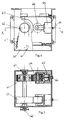
- Fig. 1 is a longitudinal section view of one embodiment of the present invention;
- Fig. 2 is a perspective view of one embodiment of the seal structure of Fig. 1;
- Fig. 3 is a perspective view of another embodiment of the seal structure of Fig. 1;
- Fig. 4 is a side view of said pulling mechanism of Fig. 1;
- Fig. 5 is a half-sectional view along the line of A-A of Fig. 4;
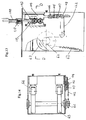
- Fig 6 is a top view with partial sectional view at the closing time of another embodiment of the open-close pulling mechanism of the present invention;
- Fig 7 is a view cut along B-B line of Fig. 6;
- Fig 8 is a perspective view of the pulling roller in Fig. 6 and 7;
- Fig 9 is a top view of the pulling roller at the state of opening as shown in Figs. From 6-8;
- Fig 10 is a view cut along C-Cline of Fig. 9;
- Fig 11 is a perspective view of another embodiment of the present invention;
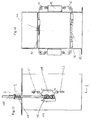
- Fig. 12 is a top view of the seat ring in Fin. 11;
- Fig. 13 is a view showing the transmission mechanism mounted in the case body of Fig. 12;
- Fig. 14 is a sectional view cut along D-D line of Fig. 13;
- Fig. 15 is a view showing another transmission case body of Fig. 14;
- Fig. 16 is a view showing the sealing structure along E-E line of Fig 15;
-
- Referring to Fig. 1, the toilet ware of the present invention includes a
case body 3, a shaped cavity 7 formed on saidcase body 3, aseat ring 8 provided under said shaped cavity, a cover ofplastic bag 10 provided over the periphery of said case body, wherein said cover is formed by outerprotective board 25 and innerprotective cover 26 and said plastic bag is provided between the two protective boards. Saidplastic bag 10 is preferably dissoluble plastics. Saidcase body 3 is mounted on apedal 2 which has the rear end hinged with a base 1 and may swing around a supporting point O. Between said base and the front a end of saidpedal 2 is provided with a press spring 11. And saidpedal 2 is hinged with twocranks 21,23 which control the operation of said open-close pulling mechanism provided in saidcase body 3. Each of said cranks has one end rolled on a supportingboard 13 of said base 1, and the other end connects respectively to said open-close pulling mechanism viapulling ropes - The moving directions of said
cranks 21 and 23 are opposite and areset spring 12 is provided between said swing end of said crank 21 and said base. - The lower end of said
case body 3 connects a excrement holding case (not shown) via a flexible tube 9. - Referring to Figs. 2-5. The open-close pulling mechanism of the present invention includes a sealing means and a pulling means. Said sealing means has a pair of upper sealing
doors 41 mounted on anupper partition board 31 and a pair oflower sealing doors 51 mounted on anlower partition board 32. Said sealing doors have respectivelyspring doors 41 connect to twopulling ropes 24 viapulleys doors 51 connect to the upper sealingdoors 41 via a pair ofpulling ropes 44 andpulleys 43 and 53. Saidrope 24 connects with saidcrank 23 and the force of saidspring 42 is bigger than that of saidspring 52. Said pulling means is provided between said upper andlower doors wheel 63 mounted on atransmission shaft 60. Said pullingwheel 63 should be preferable two. In addition, there is also provided atension wheel 64 cooperated with said pullingwheels 63. Saidtension wheel 64 adjusts the press between itself and pullingwheel 63 via adjustingscrew 66 and support 65. On said transmission shaft there is provided achain wheel 62 which is turned by a chain connected on saidrope 22 and the other end of said chain connects to chain saidcase body 3 via anextension spring 67. The force of saidreset spring 12 is stronger than that of saidextension spring 67. - Said crank 21 connects to said pulling
rope 22 which controls said sealing means, and saidcrank 23 connects to said pullingrope 24 which controls said pulling means. - Between said
chain wheel 62 and pullingwheel 63, there is provided a surpassing clutch which provided within said pullingwheel 63 or on saidchain wheel 62. Thesimplest chain wheel 62 is an ordinary flywheel widely used on bike. - Fig.3 shows another embodiment of said seal structure. It differs from that of Fig.2 in that said
press springs extension springs - Figs. 6-10 show another embodiment of pulling open-close structure.
- Open-close pulling mechanism mounted in said
case body 3 includes two symmetrically-arrangedrollers 70, of which each has two pullingwheels 71 which connect to one another via aplywood board 72 positioned along the axis of said rollers. The maximum width of saidplywood board 72 is equal to the diameter of therollers 70 and the thickness of saidboard 72 is less than half of radius of said rollers. Said tworollers 70 turn towards the opposite direction driven by saidchain wheel 62 via transmission means 68 and 69. Tworollers 70 has a pressing means on one of them, such as saidscrew 66 and support 65. - When open-close pulling mechanism as shown by Figs 6-10 is adopted, only one crank 21 may be provided, of which its swing end drives said
chain wheel 62 to rotate via saidrope 22 and chains connected with said rope. The other end of the chain connects to said case body via saidextension 67. The force of said resetspring 12 connected between said swing end of said crank 21 and base 1 is stronger than that ofspring 67. Saidchain wheel 62 may be above flywheel. - Figs. 6-7 show that said
roller 70 is in a state of close and saidplastic bag 10 is clipped and sealed by twoplywood boards 72, and Figs 9-10 show that saidroller 71 is in a open state and saidplastic bag 10 may go through a room shaped between saidboards 72. Said pullingwheels 71 are used to pull saidplastic bag 10. - Figs. 11-16 show another embodiment of the present invention, which adopts and open-close pulling mechanism which, is the same as that of Figs. 1-10. The only difference is that the operation is initiated by seating pressing.
- Referring to Figs. 11-14. The toilet ware includes a
case body 3, a shaped cavity 7 mounted on said case body, aseat ring 8 provided on said shaped cavity, a plastic bag cover (not shown) provided on the periphery of said case body, and open-close pulling mechanism mounted in saidcase body 3. At least an open- close pulling performing mechanism provided around the periphery of said plastic bag, which has acontrol rod 100 that may vertically glide. Theseat ring 8 has its rear and hinged with said shaped cavity 7, saidcontrol rod 100 has its upper end against saidring 8, which is effected by aspring 110 mounted on saidrod 100. The lower part of saidrod 100 is connected to atransmission mechanism 101, which includes at least onegear wheel 102 movably fixed on saidrod 100, a fixed rack joggled with saidgear wheel 102 and agliding gear wheel 104. Provided on saidrack 104 there is a pullingrope 122 connected to the open-close pulling mechanism, and said pullingrope 122 is connected to said open-close pulling mechanism by a pulley range expanding mechanism. Said pulley range expanding mechanism includes a first and secondmovable pulley 105 and 106 mounted on saidgliding rack 104, a first and second fixedpulley rope 122 which has one end fixed in saidcase body 3 and goes on in turn around the first movable pulley 105, the first fixedpulley 107, the secondmovable pulley 106 and second fixedpulley 108, and is then connected to said open-close pulling mechanism. In Figs. 11-16, the parts identical to those in Figs. 1-10 are indicated by the same marks. - Figs. 15-16 shows another scaling structure including also a pair of
upper sealing doors 41 and a pair oflower sealing doors 51, as well assprings rack 103,movable rack 104,gear wheel 102 andcontrol rod 100, wherein said upper and lower sealing doors are connected to the upper and lower ends ofmovable rack 104 byropes 111 and 112, so as to pull said sealing door to open and close. - The next is description of the process of operation by reference to Figs. 1-5.
- When a man steps on said
pedal 2, no matter whether he seats on saidseat ring 8 or not,pedal 2 will rotate around point O. Crank 21 then overcomes the force ofreset spring 12 and rotate in a counter clockwise way.Rope 22 in turn, under the function ofspring 67, moves to the right side of Fig. 2 so as to consequently makechain 62 to rotate. Since there is a surpassing clutch provided betweenchain wheel 62 and pullingwheel 63, pulling wheel does not move whenchain wheel 62 freely rotates. At the same time, crank 23 rotates clockwise bringingrope 24 to move leftward, pulling open upper sealingdoor 41. Lower sealingdoor 51 closes at function ofspring 52. At this time there is a clean room for excrement. When one leftpedal 2, resetspring 12 overcomes the force of spring 67 (the force ofspring 12 is stronger than of spring 67) and pulls theplastic bag 10 containing excrement downward via pullingwheel 63 rotated bychain wheel 62 making shaped cavity 7 to be a clean room while upper sealing door41, activated byspring 42, overcomes the force ofspring 52 and openslower sealing door 51, making excrement fall into said excrement holding case, finishing one use of toilet. The using method is similar to that or other embodiments. - The embodiment of the present invention as described above may, evidently be varied within concept of the present invention, and all the variations are within capability of ordinary technicians. For
example chain wheel 62 may be replaced by a belt wheel, said pulling roller may be a drum wheel as shown in PCT/CN96/00009 and an expending ring as described in PCT/CN96/00009 may also be fixed within said shaped cavity 7. Under said pulling wheel there may be provided with a lower sealing door which opens or closes according to its action. Said lower sealing door may be a turning gate rotating around axis.
Claims (12)
- A fully automatic toilet ware without flushing including a case body, a shaped cavity mounted on said case body, a seat ring provided on said shaped cavity, a cover for a plastic bag provided over periphery of said case body and an open-close pulling mechanism mounted in said case body for controlling connection between said shaped cavity and an excrement holding case fixed under said case body, characterized in that said case body is fixed on a pedal which has its rear and hinged with a base and its front end structured as a swing end, and between the end said base there is provided with a press spring, and said pedal is at least hinged with a crank for controlling the operation of said open-close pulling mechanism, and said crank has one end rolled in a supporting board of said base and the other end connected with said open-close pulling mechanism.
- A toilet ware in accordance with claim 1. Characterized in that said open-close mechanism includes a sealing means and a pulling means, said sealing means has a pair of upper sealing doors mounted on an upper partition board and a pair of lower sealing doors mounted on a lower partition board and said sealing doors have respectively springs which may force them to close and said upper and lower sealing doors are alternatively opened or closed, and two upper doors are connected with two pulling ropes through pulleys and two lower doors are connected with said two upper doors through a pair of pulling ropes and pulleys, and a spring of said upper sealing doors are stronger than that of lower doors; said pulling means is provided between said upper and lower sealing doors and has a pulling wheel mounted on a transmission shaft, a tension wheel, and a chain wheel mounted on said transmission shaft, and between said chain wheel and pulling wheel there is a surpassing clutch;
- A toilet ware in accordance with claim 1 characterized in that said open-close pulling mechanism includes a sealing means and a pulling means, said sealing means has a pair of upper sealing doors mounted on an upper partition board, and said upper sealing doors have springs which may force them closed and are connected with two pulling ropes through pulleys, said ropes are connected with said first crank, said pulling means are provided under said sealing doors and have a pulling wheel mounted on an mounted on said transmission shaft,
there are two cranks, one first crank for controlling said upper sealing doors and one there are two cranks for controlling said pulling means. - A toilet ware in accordance with claims 2 or 3 characterized in that said first crank and second crank have opposite direction of movement, and said first crank has its swing end drive a chain wheel rotate through a pulling rope and a chain connected with said rope; said chain has the other end connected with said case body through an extension spring, and between said swing end of said first crank and said base there is connected with a reset spring, said reset spring has a stronger force than that of the extension spring, said second crank is connected with a pair of ropes bringing said upper sealing doors; there is a surpassing clutch provided between said chain wheels and pulling wheels.
- A toilet ware in accordance with claim 1 characterized in that said open-close pulling mechanism includes two symmetrically provided rollers, of which each has two pulling wheel parts which are connected to one another by a plywood board positioned along the axis of said rollers, said plywood board has its maximum width equal to the diameter of said rollers and its thickness less than the radius of said rollers, said two rollers rotate in opposite directions driven by said transmission means.
- A toilet ware in accordance with claims 1 or 5 characterized in that said cranks have their swing ends drive a chain wheel through a rope and a chain connected with said rope, said rope has the other end connected with said case body through a extension spring, between said swing end of said crank and said base there is connected with a reset spring, said reset spring has stronger force than that of said extension spring
- A fully automatic toilet ware without flushing including a case body, a shaped cavity mounted on said case body, a seat ring provided on said shaped cavity, a cover for plastic bag provide over periphery of said case body and an open-close pulling mechanism mounted in said case body for controlling connection between said shaped cavity and an excrement holding case under said case body, characterized in that at least one vertically movable control rod is provided over said cover of plastic bag, said rear end of said seat ring is hinged on said shaped cavity, said control rod has its upper end against said seat ring and the lower part of said control rod has at least one gear wheel movably fixed, said gear wheel is jogged with one fixed rack and a movable rack, said open-close pulling mechanism is connected with said movable rack.
- A toilet ware in accordance with claim 7 characterized in that said open-closed pulling mechanism is connected with said movable rack through a pulling rope.
- A toilet ware in accordance with claim 8 characterized in that on said movable rack there is mounted a first and a second movable pulleys, and on said case body there is mounted a with a first and second fixed pulleys, said pulling rope have one end fixed on said case body go on around said first movable pulley, first fixed pulley, second movable pulley and second fixed pulley, and then is connected with said open-closed pulling mechanism.
- A toilet ware in accordance with claims 1 or 5 characterized in that under said pulling wheel there is provide with a lower sealing door which may be opened and closed along its action.
- A toilet ware in accordance with claim 10 characterized in that said lower sealing door is a turning door which may rotate around said axis.
- A toilet ware in accordance with claims 1,2,3,5,7,8,9 or 11 characterized in that there is an expanding ring fixed within said shaped cavity.
Applications Claiming Priority (1)
| Application Number | Priority Date | Filing Date | Title |
|---|---|---|---|
| PCT/CN1996/000027 WO1997039673A1 (en) | 1996-04-24 | 1996-04-24 | Completely automatic waterless closet |
Publications (3)
| Publication Number | Publication Date |
|---|---|
| EP0906744A1 true EP0906744A1 (en) | 1999-04-07 |
| EP0906744A4 EP0906744A4 (en) | 1999-06-16 |
| EP0906744B1 EP0906744B1 (en) | 2003-10-22 |
Family
ID=4574958
Family Applications (1)
| Application Number | Title | Priority Date | Filing Date |
|---|---|---|---|
| EP96910897A Expired - Lifetime EP0906744B1 (en) | 1996-04-24 | 1996-04-24 | Completely automatic waterless closet |
Country Status (9)
| Country | Link |
|---|---|
| US (1) | US6212701B1 (en) |
| EP (1) | EP0906744B1 (en) |
| KR (1) | KR100310602B1 (en) |
| AU (1) | AU728898B2 (en) |
| BR (1) | BR9612601A (en) |
| CA (1) | CA2253775C (en) |
| DE (1) | DE69630470T2 (en) |
| ES (1) | ES2210357T3 (en) |
| WO (1) | WO1997039673A1 (en) |
Cited By (4)
| Publication number | Priority date | Publication date | Assignee | Title |
|---|---|---|---|---|
| GB2409866A (en) * | 2004-01-08 | 2005-07-13 | Medicart Int Ltd | Waste packaging system |
| DE202010009966U1 (en) | 2010-07-06 | 2011-10-26 | Michael Winter | Waterless mobile film hose toilet |
| DE202011001413U1 (en) | 2011-01-12 | 2012-04-17 | Michael Winter | Waterless compact mobile film hose toilet |
| DE202011104936U1 (en) | 2011-08-29 | 2012-12-03 | Michael Winter | Waterless, low-odor mobile film hose toilet |
Families Citing this family (15)
| Publication number | Priority date | Publication date | Assignee | Title |
|---|---|---|---|---|
| GB0114312D0 (en) * | 2001-06-12 | 2001-08-01 | Sangenic International Ltd | Spool for a waste storage device |
| US6941733B2 (en) * | 2003-04-03 | 2005-09-13 | Playtex Products, Inc. | Waste disposal apparatus |
| GB0324764D0 (en) | 2003-10-23 | 2003-11-26 | Sangenic International Ltd | Waste storage device |
| CN100479731C (en) * | 2003-11-17 | 2009-04-22 | 刘彻 | Environmental protection flushing free closet |
| CN100446708C (en) * | 2005-04-01 | 2008-12-31 | 长沙金凤滩高科技有限责任公司 | Stool device for inteligent environment-protection lavatory |
| GB0622909D0 (en) * | 2006-11-16 | 2006-12-27 | Sangenic International Ltd | Waste storage device |
| CN101822503B (en) * | 2010-04-09 | 2011-09-28 | 薛源 | Emergency ecological public lavatory for disaster areas |
| CN102535610B (en) * | 2010-12-28 | 2014-03-12 | 福州耕耘专利开发有限公司 | Bottom-drawing blowdown type toilet stool |
| GB201103429D0 (en) | 2011-02-28 | 2011-04-13 | Sangenic International Ltd | Improved waste storage device and cassette |
| CN102283608B (en) * | 2011-07-14 | 2013-01-02 | 牟光灵 | Novel environment-friendly and energy-saving anhydrous sanitary toilet |
| US9357890B2 (en) | 2012-02-20 | 2016-06-07 | Sanitation Creations, Llc | Waterless toilet system and methods of use |
| US9364124B2 (en) | 2012-02-20 | 2016-06-14 | Sanitation Creations, Llc | Waterless toilet system and methods of use |
| CN103349525B (en) * | 2013-06-25 | 2018-02-13 | 牟光灵 | The new just lavatory of environmental protection and energy saving dry sanitary |
| KR101950753B1 (en) * | 2013-08-06 | 2019-02-21 | 니혼 세이프티 가부시키가이샤 | Film sealing mechanism |
| CN112716343B (en) * | 2021-01-23 | 2022-04-12 | 郑州云茂实业有限公司 | Biological filler sewage discharging device for dry toilet and using method thereof |
Citations (3)
| Publication number | Priority date | Publication date | Assignee | Title |
|---|---|---|---|---|
| CH525134A (en) * | 1970-01-06 | 1972-07-15 | Pactosan Ab | Device for collecting solid or liquid waste |
| US3693193A (en) * | 1970-11-23 | 1972-09-26 | Coleman Co | Portable sanitary toilet |
| FR2725421A1 (en) * | 1994-10-05 | 1996-04-12 | Lecomte Michel Raymond Georges | Device for packaging of hospital waste |
Family Cites Families (9)
| Publication number | Priority date | Publication date | Assignee | Title |
|---|---|---|---|---|
| US2671906A (en) * | 1952-11-15 | 1954-03-16 | Robert W Potts | Liner for sanitary closets |
| US3452368A (en) * | 1966-10-07 | 1969-07-01 | Fts Corp | Portable waste disposer |
| US3665522A (en) * | 1969-11-17 | 1972-05-30 | Pactosan Ab | Apparatus for collecting solid or liquid wastes |
| US3619822A (en) * | 1969-11-18 | 1971-11-16 | Thomas Carmichael | Sanitary closet |
| US3878572A (en) * | 1973-09-21 | 1975-04-22 | Eleon Gustav Eriksson | Collecting device for solid or liquid waste material |
| SE385434B (en) * | 1974-09-20 | 1976-07-05 | Trailer Finanse Ab | DEVICE AT TOILETS |
| DE3941939A1 (en) * | 1989-12-19 | 1991-06-20 | Johannes Loebbert | DRY TOILET WITH LOCKABLE CONTAINER TO RECEIVE FAECALS |
| FR2698025B1 (en) * | 1992-11-13 | 1994-12-16 | Innovation Ingenierie Integrat | Waste recovery and storage device. |
| ES2176431T3 (en) | 1996-02-02 | 2002-12-01 | Englong He | TOILET ASSEMBLY WITHOUT WATER LAUNCH. |
-
1996
- 1996-04-24 AU AU53960/96A patent/AU728898B2/en not_active Ceased
- 1996-04-24 CA CA002253775A patent/CA2253775C/en not_active Expired - Fee Related
- 1996-04-24 EP EP96910897A patent/EP0906744B1/en not_active Expired - Lifetime
- 1996-04-24 BR BR9612601A patent/BR9612601A/en not_active Application Discontinuation
- 1996-04-24 US US09/171,620 patent/US6212701B1/en not_active Expired - Fee Related
- 1996-04-24 KR KR1019980708543A patent/KR100310602B1/en not_active IP Right Cessation
- 1996-04-24 ES ES96910897T patent/ES2210357T3/en not_active Expired - Lifetime
- 1996-04-24 DE DE69630470T patent/DE69630470T2/en not_active Expired - Fee Related
- 1996-04-24 WO PCT/CN1996/000027 patent/WO1997039673A1/en active IP Right Grant
Patent Citations (3)
| Publication number | Priority date | Publication date | Assignee | Title |
|---|---|---|---|---|
| CH525134A (en) * | 1970-01-06 | 1972-07-15 | Pactosan Ab | Device for collecting solid or liquid waste |
| US3693193A (en) * | 1970-11-23 | 1972-09-26 | Coleman Co | Portable sanitary toilet |
| FR2725421A1 (en) * | 1994-10-05 | 1996-04-12 | Lecomte Michel Raymond Georges | Device for packaging of hospital waste |
Non-Patent Citations (1)
| Title |
|---|
| See also references of WO9739673A1 * |
Cited By (4)
| Publication number | Priority date | Publication date | Assignee | Title |
|---|---|---|---|---|
| GB2409866A (en) * | 2004-01-08 | 2005-07-13 | Medicart Int Ltd | Waste packaging system |
| DE202010009966U1 (en) | 2010-07-06 | 2011-10-26 | Michael Winter | Waterless mobile film hose toilet |
| DE202011001413U1 (en) | 2011-01-12 | 2012-04-17 | Michael Winter | Waterless compact mobile film hose toilet |
| DE202011104936U1 (en) | 2011-08-29 | 2012-12-03 | Michael Winter | Waterless, low-odor mobile film hose toilet |
Also Published As
| Publication number | Publication date |
|---|---|
| CA2253775A1 (en) | 1997-10-30 |
| CA2253775C (en) | 2003-01-14 |
| ES2210357T3 (en) | 2004-07-01 |
| EP0906744A4 (en) | 1999-06-16 |
| KR100310602B1 (en) | 2001-11-15 |
| EP0906744B1 (en) | 2003-10-22 |
| BR9612601A (en) | 1999-07-20 |
| DE69630470T2 (en) | 2004-07-22 |
| US6212701B1 (en) | 2001-04-10 |
| DE69630470D1 (en) | 2003-11-27 |
| KR20000010634A (en) | 2000-02-25 |
| AU728898B2 (en) | 2001-01-18 |
| WO1997039673A1 (en) | 1997-10-30 |
| AU5396096A (en) | 1997-11-12 |
Similar Documents
| Publication | Publication Date | Title |
|---|---|---|
| EP0906744B1 (en) | Completely automatic waterless closet | |
| JPS62121291A (en) | Opening and closing operation system of industrial door | |
| CA2879495A1 (en) | Bi-parting, bi-directional door system | |
| CA2139211A1 (en) | Automatic Lowering Device for Toilet Seat and Lid | |
| KR100312569B1 (en) | Automatic opening and shutting apparatus of a sliding door | |
| JP2506668Y2 (en) | Back door automatic opening / closing device | |
| JP3060706U (en) | Fully automatic toilet equipment that does not require washing | |
| MXPA98008835A (en) | No-disposal of water totally automat | |
| CN2286023Y (en) | Full-automatic closet without flushing | |
| CN2269172Y (en) | Flushing-free closet | |
| RU2150225C1 (en) | All-automatic toilet bowl without facilities for flush-washing with delivery liquid streams (versions) | |
| JP2003531318A (en) | Automatic door opening and closing device | |
| CN216197419U (en) | Male urinal with door | |
| KR102557873B1 (en) | Driving Device for Door | |
| JPH11311058A (en) | Operating force assisting device for movable fittings of window, door, or the like | |
| JPH06221054A (en) | Opening/closing device for automatically opened/closed sliding door | |
| KR102107007B1 (en) | Opening and shutting apparatus for canopy interworking with door | |
| KR200355811Y1 (en) | A locking equipment for system window and door | |
| CN112897385B (en) | Be used for rescuing sandy beach and put superficial dolphin device | |
| CN214997317U (en) | Fire control is with two-way fire prevention of fleing roll curtain | |
| CN1099862C (en) | Fully automatic closet without flushing | |
| JPS6160339A (en) | Step for vehicle | |
| JPH1132945A (en) | Opening and closing device for toilet seat and toilet cover | |
| CN1137367A (en) | Fully automatic closet without flushing | |
| CN114704174A (en) | Human body non-contact mechanical control method and system for partition door of public place |
Legal Events
| Date | Code | Title | Description |
|---|---|---|---|
| PUAI | Public reference made under article 153(3) epc to a published international application that has entered the european phase |
Free format text: ORIGINAL CODE: 0009012 |
|
| AK | Designated contracting states |
Kind code of ref document: A1 Designated state(s): DE ES FR GB IT |
|
| A4 | Supplementary search report drawn up and despatched |
Effective date: 19990503 |
|
| AK | Designated contracting states |
Kind code of ref document: A4 Designated state(s): DE ES FR GB IT |
|
| 17P | Request for examination filed |
Effective date: 19990129 |
|
| 17Q | First examination report despatched |
Effective date: 20020507 |
|
| GRAH | Despatch of communication of intention to grant a patent |
Free format text: ORIGINAL CODE: EPIDOS IGRA |
|
| GRAH | Despatch of communication of intention to grant a patent |
Free format text: ORIGINAL CODE: EPIDOS IGRA |
|
| GRAA | (expected) grant |
Free format text: ORIGINAL CODE: 0009210 |
|
| AK | Designated contracting states |
Kind code of ref document: B1 Designated state(s): DE ES FR GB IT |
|
| REG | Reference to a national code |
Ref country code: GB Ref legal event code: FG4D |
|
| REF | Corresponds to: |
Ref document number: 69630470 Country of ref document: DE Date of ref document: 20031127 Kind code of ref document: P |
|
| REG | Reference to a national code |
Ref country code: ES Ref legal event code: FG2A Ref document number: 2210357 Country of ref document: ES Kind code of ref document: T3 |
|
| ET | Fr: translation filed | ||
| PLBE | No opposition filed within time limit |
Free format text: ORIGINAL CODE: 0009261 |
|
| STAA | Information on the status of an ep patent application or granted ep patent |
Free format text: STATUS: NO OPPOSITION FILED WITHIN TIME LIMIT |
|
| 26N | No opposition filed |
Effective date: 20040723 |
|
| PGFP | Annual fee paid to national office [announced via postgrant information from national office to epo] |
Ref country code: GB Payment date: 20050418 Year of fee payment: 10 |
|
| PGFP | Annual fee paid to national office [announced via postgrant information from national office to epo] |
Ref country code: ES Payment date: 20050421 Year of fee payment: 10 |
|
| PGFP | Annual fee paid to national office [announced via postgrant information from national office to epo] |
Ref country code: FR Payment date: 20050426 Year of fee payment: 10 |
|
| PGFP | Annual fee paid to national office [announced via postgrant information from national office to epo] |
Ref country code: DE Payment date: 20050622 Year of fee payment: 10 |
|
| PG25 | Lapsed in a contracting state [announced via postgrant information from national office to epo] |
Ref country code: GB Free format text: LAPSE BECAUSE OF NON-PAYMENT OF DUE FEES Effective date: 20060424 |
|
| PG25 | Lapsed in a contracting state [announced via postgrant information from national office to epo] |
Ref country code: ES Free format text: LAPSE BECAUSE OF NON-PAYMENT OF DUE FEES Effective date: 20060425 |
|
| PGFP | Annual fee paid to national office [announced via postgrant information from national office to epo] |
Ref country code: IT Payment date: 20060430 Year of fee payment: 11 |
|
| PG25 | Lapsed in a contracting state [announced via postgrant information from national office to epo] |
Ref country code: DE Free format text: LAPSE BECAUSE OF NON-PAYMENT OF DUE FEES Effective date: 20061101 |
|
| GBPC | Gb: european patent ceased through non-payment of renewal fee |
Effective date: 20060424 |
|
| REG | Reference to a national code |
Ref country code: FR Ref legal event code: ST Effective date: 20061230 |
|
| REG | Reference to a national code |
Ref country code: ES Ref legal event code: FD2A Effective date: 20060425 |
|
| PG25 | Lapsed in a contracting state [announced via postgrant information from national office to epo] |
Ref country code: FR Free format text: LAPSE BECAUSE OF NON-PAYMENT OF DUE FEES Effective date: 20060502 |
|
| PG25 | Lapsed in a contracting state [announced via postgrant information from national office to epo] |
Ref country code: IT Free format text: LAPSE BECAUSE OF NON-PAYMENT OF DUE FEES Effective date: 20070424 |