EP0906735B1 - Jewel provided with a decorative element - Google Patents
Jewel provided with a decorative element Download PDFInfo
- Publication number
- EP0906735B1 EP0906735B1 EP98117615A EP98117615A EP0906735B1 EP 0906735 B1 EP0906735 B1 EP 0906735B1 EP 98117615 A EP98117615 A EP 98117615A EP 98117615 A EP98117615 A EP 98117615A EP 0906735 B1 EP0906735 B1 EP 0906735B1
- Authority
- EP
- European Patent Office
- Prior art keywords
- item
- decorative element
- carrier
- jewellery according
- tube
- Prior art date
- Legal status (The legal status is an assumption and is not a legal conclusion. Google has not performed a legal analysis and makes no representation as to the accuracy of the status listed.)
- Expired - Lifetime
Links
- 239000010437 gem Substances 0.000 title 1
- 229910001751 gemstone Inorganic materials 0.000 title 1
- 229910000639 Spring steel Inorganic materials 0.000 claims description 23
- 239000000463 material Substances 0.000 claims description 3
- 229910052751 metal Inorganic materials 0.000 claims description 3
- 230000000717 retained effect Effects 0.000 claims 3
- 239000002184 metal Substances 0.000 claims 2
- 229920003023 plastic Polymers 0.000 claims 2
- 239000004033 plastic Substances 0.000 claims 2
- 230000000295 complement effect Effects 0.000 claims 1
- 229920002994 synthetic fiber Polymers 0.000 description 1
- 230000007704 transition Effects 0.000 description 1
Images

Classifications
-
- G—PHYSICS
- G04—HOROLOGY
- G04B—MECHANICALLY-DRIVEN CLOCKS OR WATCHES; MECHANICAL PARTS OF CLOCKS OR WATCHES IN GENERAL; TIME PIECES USING THE POSITION OF THE SUN, MOON OR STARS
- G04B37/00—Cases
- G04B37/14—Suspending devices, supports or stands for time-pieces insofar as they form part of the case
- G04B37/1486—Arrangements for fixing to a bracelet
-
- A—HUMAN NECESSITIES
- A44—HABERDASHERY; JEWELLERY
- A44C—PERSONAL ADORNMENTS, e.g. JEWELLERY; COINS
- A44C17/00—Gems or the like
- A44C17/02—Settings for holding gems or the like, e.g. for ornaments or decorations
- A44C17/0208—Settings for holding gems or the like, e.g. for ornaments or decorations removable
- A44C17/0216—Settings for holding gems or the like, e.g. for ornaments or decorations removable with automatic locking action, e.g. by using a spring
-
- A—HUMAN NECESSITIES
- A44—HABERDASHERY; JEWELLERY
- A44C—PERSONAL ADORNMENTS, e.g. JEWELLERY; COINS
- A44C5/00—Bracelets; Wrist-watch straps; Fastenings for bracelets or wrist-watch straps
- A44C5/14—Bracelets; Wrist-watch straps; Fastenings for bracelets or wrist-watch straps characterised by the way of fastening to a wrist-watch or the like
- A44C5/142—Cord type straps
Definitions
- the object of the invention is so jewelry and decorative element to coordinate with each other that easy assembly and disassembly of the Decorative element on the piece of jewelry with nevertheless secure mounting in the Use position of the piece of jewelry is reached.
- US-A-2 431 232 discloses a piece of jewelry with a carrier and a decorative element detachably held on this.
- the basic idea of the invention thus includes two components, namely the releasable mounting of the decorative element on the carrier and the definition of a locking position of the decorative element on the Carrier in which the decorative element by means of elastically acting holding elements locked and secured against unintentional removal is.
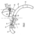
- a spring steel bracket 10 with a rectangular cross section serves as the carrier, that in its middle part 10A straight and in the two adjoining areas 10B, 10C is arcuate. in the The distance from its straight area is one on both sides Abutment in the form of a sleeve 11 and 12 out.
- this Spring steel bracket 10 are between the central part 10A and Sleeves 11 and 12 in the illustrated embodiment two elastically deformable hoses made of rubber material or synthetic material, the rear end of which is attached the sleeve 11 or 12 abuts and in the transition area to the rectilinear central section of the spring steel bracket 10 lying End faces 31 and 41 of a sleeve-like plug-on element 35.45 are formed.
- the two sleeves 11 and 12 serve as Abutment, since a closed hose 50 of defined length Distance between these two sleeves 11 and 12 specifies.
- the clip-on elements 35, 45 are slidable on the middle part 10A.
- this Storage thus the distance X of the two opposite End faces 31 and 41 of the two plug-on elements 35, 45 is variable and the introduction of a decorative element 20 on the straight line Section 10A of the spring steel bracket 10 allowed.
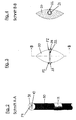
- the end faces 31 and 41 of the sleeve-shaped push-on elements 35, 45 have one first profiling P1 on the shown Embodiment as a section of a spherical segment is trained.
- the decorative element 20 has a sleeve-shaped Insert 21, whose internal volume through an axial slot 22 of the outside of the decorative element 20 is accessible.
- the inside cross section the insert 21 and the axial slot 22 are such matched to the cross section of the spring steel bracket 10 that the middle part 10A of the spring steel bracket 10 between the two End faces 31 and 41 in the axial slot 22 to Internal cross section can be inserted and the decorative element 20 in this position by an angle of preferably 90 ° on the Spring steel bracket 10 can be rotated such that in the twisted position a removal of the decorative element 20 from Spring steel bracket 10 is no longer possible because the width of the Axial slot 22 the removal of the spring steel bracket 10 with its wider side surfaces not allowed.
- the insert 21 now faces on its two opposite ends 23 and 24 also have a profile P2, which in the exemplary embodiment also as sections of a Ball segment is designed according to the profile P1.
- the two spherical shell profiles P1 and P2 are now open their respective end faces 31, 41 and 23, 24 positioned that they come into positive engagement when the decorative element 20 in the 90 ° rotated position on the spring steel bracket 10 (where it can no longer be removed). Under the restoring force of the elastic hoses 30 and 40, the decorative element 20 comes in exactly this position then via the corresponding profiles P1, P2 in engagement with the two end faces of the plug-on elements 35 and 45, so that by snapping or snapping the captive mounting of the decorative element 20 on the Spring steel bracket 10 is secured.
- FIG. 5 shows the assembly of the decorative element 20 briefly illustrates on the spring steel bracket 10:
- the starting position is that shown in Figure 5; by shift in the direction of arrow 1, the decorative element 20 on the Attach the spring steel bracket 10 or the spring steel bracket 10 over the Axial slot 22 in the inner cross section of the sleeve-shaped insert 21 insert when the two hoses 30.40 in their elastic retracted position so that the clear dimension between the two end faces of the hoses is sufficient to the insert 21 together with profiles P2 on the spring steel bracket 10 sit up.
- the two are in this position Profiling P1 and P2 not in positive engagement, the two Hoses 30 and 40 are thus spread apart Position held.
- the piece of jewelry according to the invention is usually connected can be used with a supplementary part of a defined length, for example the hose 50 shown, or a band or a chain, which is conveniently on the two sleeves 11 and 12th is attached and has a closure.
- the piece of jewelry according to the invention can thus be of various sizes
- the decorative element 20 could also be a Time display element included, creating a very idiosyncratic clock would be feasible.
- Metal elements such as spring washers or spiral springs alone or in combination with a hose can be used if this is used to define the Holding forces and / or seems necessary for design reasons.
- the Use of such a piece of jewelry as part of a design concept is therefore very diverse.
Landscapes
- Physics & Mathematics (AREA)
- General Physics & Mathematics (AREA)
- Adornments (AREA)
Description
Aufgabe der Erfindung ist es, Schmuckstück und Dekorelement so aufeinander abzustimmen, daß eine leichte Montage und Demontage des Dekorelementes am Schmuckstück bei dennoch sicherer Halterung in der Gebrauchsposition des Schmuckstückes erreicht wird.The object of the invention is so jewelry and decorative element to coordinate with each other that easy assembly and disassembly of the Decorative element on the piece of jewelry with nevertheless secure mounting in the Use position of the piece of jewelry is reached.
US-A-2 431 232 offenbart ein Schmuckstück mit einem Träger und einem an diesem lösbar gehaltenen Dekorelement.US-A-2 431 232 discloses a piece of jewelry with a carrier and a decorative element detachably held on this.
Die Aufgabe wird erfindungsgemäß gemäß dem kennzeichnenden Teil des Patentanspruchs 1 gelöst.The object is achieved according to the characterizing part of claim 1 solved.
Der Grundgedanke der Erfindung beinhaltet somit zwei Komponenten, nämlich die lösbare Halterung des Dekorelementes auf dem Träger und die Definition einer Arretierposition des Dekorelementes auf dem Träger, in der das Dekorelement mittels elastisch wirkender Halteelemente verriegelt und gegen unbeabsichtiges Entnehmen gesichert ist.The basic idea of the invention thus includes two components, namely the releasable mounting of the decorative element on the carrier and the definition of a locking position of the decorative element on the Carrier in which the decorative element by means of elastically acting holding elements locked and secured against unintentional removal is.
Sowohl als Dekorelement als auch als Träger können die verschiedenartigsten Elemente verwendet werden, die insbesondere hinsichtlich ihres Designs aufeinander abgestimmt sein können, aber auch hinsichtlich ihres jeweiligen Verwendungszwecks (Teil eines Ringes, eines Colliers, eines Armbandes oder ähnlichem) in vielfältiger Weise ausgebildet sein können, wobei lediglich die eingangs erwähnte Grundfunktion (lösbare Halterung und elastisch wirkendes Halteelement) gewährleistet sein muß.The most varied can be used both as a decorative element and as a support Items are used that are particularly regarding their design can be coordinated, but also in terms of their respective purpose (part of a ring, a necklace, a bracelet or the like) in various Can be designed in such a way, only the one mentioned at the beginning Basic function (detachable holder and elastic holding element) must be guaranteed.
Ein bevorzugtes Ausführungsbeispiel eines solchen. Schmuckstückes wird anhand der Zeichnungen näher erläutert: A preferred embodiment of such. jewelery is explained in more detail with reference to the drawings:
Als Träger dient ein Federstahlbügel 10 mit rechteckigem Querschnitt,
der in seinem mittleren Teil 10A gerade und in den beiden
anschließenden Bereichen 10B,10C bogenförmig ausgebildet ist. Im
Abstand von seinem geraden Bereich ist er durch beidseitig je ein
Widerlager in Form einer Hülse 11 und 12 geführt.A
Auf die beiden bogenförmigen Bereiche 10B.10C dieses
Federstahlbügels 10 sind zwischen dem mittleren Teil 10A und den
Hülsen 11 und 12 beim dargestellten Ausführungsbeispiel zwei
elastisch verformbare Schläuche 30,40 aus Gummimaterial oder
synthetischem Material aufgesteckt, deren rückwärtige Stirnseite an
die Hülse 11 bzw. 12 anstößt und deren im Übergangsbereich zu dem
geradlinigen zentralen Abschnitt des Federstahlbügels 10 liegenden
Stirnseiten 31 und 41 von einem hülsenähnlichen Aufsteckelement
35,45 gebildet werden. Die beiden Hülsen 11 und 12 dienen als
Widerlager, da ein geschlossener Schlauch 50 definierter Länge den
Abstand dieser beiden Hülsen 11 und 12 vorgibt. Die Aufsteckelemente
35,45 sind auf dem mittleren Teil 10A verschiebbar.On the two arcuate areas 10B.10C this
Von erfindungswesentlicher Bedeutung hierbei ist, daß durch diese
Lagerung somit der Abstand X der beiden gegenüberliegenden
Stirnseiten 31 und 41 der beiden Aufsteckelemente 35,45 variabel ist
und die Einführung eines Dekorelementes 20 auf den geradlinigen
Abschnitt 10A des Federstahlbügels 10 gestattet. Die Stirnseiten 31
und 41 der hülsenförmigen Aufsteckelemente 35,45 weisen hierbei eine
erste Profilierung P1 auf, die beim dargestellten
Ausführungsbeispiel als ein Abschnitt eines Kugelsegmentes
ausgebildet ist.Of essential importance to the invention is that this
Storage thus the distance X of the two opposite
End faces 31 and 41 of the two plug-on
Das Dekorelement 20, dessen Form beliebig ist bzw. ausschließlich
von Design-Überlegungen bestimmt ist, weist einen hülsenförmigen
Einsatz 21 auf, dessen Innenvolumen durch einen Axialschlitz 22 von
der Außenseite des Dekorelementes 20 zugänglich ist. Der Innenquerschnitt
des Einsatzes 21 und der Axialschlitz 22 sind dabei derart
auf den Querschnitt des Federstahlbügels 10 abgestimmt, daß der
mittlere Teil 10A des Federstahlbügels 10 zwischen den beiden
Stirnseiten 31 und 41 in den Axialschlitz 22 bis zum
Innenquerschnitt eingeführt werden kann und das Dekorelement 20 in
dieser Position um einen Winkel von bevorzugt 90° auf dem
Federstahlbügel 10 verdreht werden kann, derart, daß in der
verdrehten Position ein Abnehmen des Dekorelementes 20 vom
Federstahlbügel 10 nicht mehr möglich ist, da die Breite des
Axialschlitzes 22 die Herausnahme des Federstahlbügels 10 mit seinen
breiteren Seitenflächen nicht gestattet.The
Der Einsatz 21 weist nun auf seinen beiden gegenüberliegenden Stirnseiten
23 und 24 ebenfalls eine Profilierung P2 auf, die beim Ausführungsbeispiel
ebenfalls als Abschnitte eines
Kugelsegmentes entsprechend der Profilierung P1 ausgebildet ist.The
Die beiden Kugelschalenprofilierungen P1 und P2 sind nun so auf
ihren jeweiligen Stirnseiten 31,41 bzw. 23,24 positioniert, daß sie
in formschlüssigen Eingriff kommen, wenn das Dekorelement 20 in der
um 90° verdrehten Position auf dem Federstahlbügel 10 liegt (wo es
nicht mehr entnommen werden kann). Unter der Rückstellkraft der
elastischen Schläuche 30 und 40 kommt das Dekorelement 20 in genau
dieser Position dann über die korrespondierenden Profilierungen
P1,P2 in Eingriff mit den beiden Stirnseiten der Aufsteckelemente 35
und 45, so daß durch dieses Einschnappen oder Einrasten die
unverlierbare Halterung des Dekorelementes 20 auf dem
Federstahlbügel 10 gesichert wird.The two spherical shell profiles P1 and P2 are now open
their
Zur Verdeutlichung wird anhand der Figur 5 die Montage des Dekorelementes
20 auf den Federstahlbügel 10 kurz veranschaulicht:For the sake of clarity, FIG. 5 shows the assembly of the
Die Anfangsposition ist die in Figur 5 dargestellte; durch Verschiebung
in Richtung des Pfeils 1 läßt sich das Dekorelement 20 auf den
Federstahlbügel 10 aufstecken bzw. der Federstahlbügel 10 über den
Axialschlitz 22 in den Innenquerschnitt des hülsenförmigen Einsatzes
21 einführen, wenn die beiden Schläuche 30,40 in ihrer elastisch
zurückgezogenen Position sich befinden, so daß das lichte Maß
zwischen den beiden Stirnseiten der Schläuche ausreichend ist, um
den Einsatz 21 mitsamt Profilierungen P2 auf den Federstahlbügel 10
aufzusetzen. In dieser Position befinden sich die beiden
Profilierungen P1 und P2 nicht im Formschlußeingriff, die beiden
Schläuche 30 und 40 werden also in ihrer auseinandergespreizten
Position gehalten.The starting position is that shown in Figure 5; by shift
in the direction of arrow 1, the
Als nächste Bewegung wird das Dekorelement in Richtung des Pfeiles 2
in der aufgesteckten Position um 90° verschwenkt, in der infolge des
rechteckigen Querschnitts des Federstahlbügels 10 eine Abnahme des
Dekorelementes 20 vom Federstahlbügel 10 nicht mehr möglich ist.The next movement is the decorative element in the direction of arrow 2
pivoted by 90 ° in the attached position, in the position due to the
rectangular cross section of the spring steel bracket 10 a decrease in
In dieser Arretierposition (sozusagen der "Funktionsposition" des
Dekorelementes 20) liegen sich die beiden korrespondierenden Profilierungen
P1 und P2 auf den dann gegenüberliegenden Stirnseiten so
gegenüber, daß sie unter der elastischen Gegenkraft der beiden
Schläuche 30 und 40, die eine Schließbewegung in Richtung der Pfeile
3 ausführen, in formschlüssigen Eingriff gebracht werden. Durch
diesen formschlüssigen Eingriff der Profilierungen P1,P2 wird die
Positionierung des Dekorelementes 20 auf dem Federstahlbügel 10
gesichert, so daß ein unbeabsichtigtes Verdrehen um 90° und die
anschließende Herausnahme des Dekorelementes 20 nur dann möglich
ist, wenn mit einer entsprechenden Betätigungskraft die beiden Enden
der Schläuche 30 und 40 so weit auseinandergezogen oder auseinandergedrückt
werden, daß die beiden korrespondierenden Profilierungen P1
und P2 wieder außer Eingriff gebracht werden können.In this locking position (so to speak, the "functional position" of the
Decorative element 20) are the two corresponding profiles
P1 and P2 on the opposite ends
opposite that they are under the elastic counterforce of the two
Das erfindungsgemäße Schmuckstück wird in der Regel in Verbindung
mit einem Ergänzungsteil definierter Länge eingesetzt werden,
beispielsweise dem dargestellten Schlauch 50, oder einem Band oder
einer Kette, das zweckmäßigerweise an den beiden Hülsen 11 und 12
befestigt wird und über einen Verschluß verfügt.The piece of jewelry according to the invention is usually connected
can be used with a supplementary part of a defined length,
for example the
Das erfindungsgemäße Schmuckstück kann somit in verschiedener Größe beispielsweise Teil eines Colliers sein, bei dem aus einer Vielzahl von Dekorelementen das dem Geschmack des Benutzers am meisten entsprechende ausgewählt und eingesetzt werden kann.The piece of jewelry according to the invention can thus be of various sizes For example, be part of a necklace that consists of a large number of decorative elements that best suit the taste of the user appropriate can be selected and used.
Es ist beispielsweise auch denkbar, ein durchweg gerades
Federstahlbügelelement zu verwenden, bei dem nur einseitig ein
Schlauch aufgesetzt ist, ein solches Schmuckstück könnte dann Teil
beispielsweise eines Anhängers sein (mit dem Dekorelement als unterem
Abschluß). Beispielsweise könnte das Dekorelement 20 auch ein
Zeitanzeigeelement beinhalten, wodurch eine sehr eigenwillige Uhr
realisierbar wäre.For example, it is also conceivable to use a straight one
Spring steel bracket element to be used, where only one side
Hose is attached, such a piece of jewelry could then be part
for example, a pendant (with the decorative element as the bottom
Graduation). For example, the
Wird ein Ring mit den Komponenten gemäß der Erfindung realisiert, so
kann ein durchgehender Schlauch verwendet werden, die Hülsen 11, 12
sind in diesem Fall entbehrlich.If a ring is realized with the components according to the invention, then
a continuous hose can be used, the
Als elastische federnde Halteelemente können auch Metallelemente, wie Federscheiben oder Spiralfedern alleine oder in Kombination mit einem Schlauch eingesetzt werden, wenn dies zur Definition der Haltekräfte und/oder aus Designgründen erforderlich scheint. Die Verwendung eines solchen Schmuckstückes als Teil einer Design-Konzeption ist daher sehr vielfältig.Metal elements, such as spring washers or spiral springs alone or in combination with a hose can be used if this is used to define the Holding forces and / or seems necessary for design reasons. The Use of such a piece of jewelry as part of a design concept is therefore very diverse.
Claims (14)
- Item of jewellery, having a carrier (10) and a decorative element (20), which is detachably retained on said carrier, characterised in that a slot is provided in the decorative element (20), the internal cross-section of which slot permits the introduction/removal of the decorative element (20) on/from the carrier and the twisting of the decorative element into a locked position on the carrier, and in that at least one resiliently acting retaining member is associated with the carrier in such a manner that the spacing (X) between the end face of the retaining member and an oppositely situated end face of a counterbearing is variable in such a manner that the introduction/removal of the decorative element (20) is permitted, and the decorative element is locked in its locked position.
- Item of jewellery according to claim 1, characterised in that the carrier is a spring steel clip (10) having a substantially rectangular cross-section, and in that the resiliently acting retaining member is a first, deformable tube (30) which surrounds the spring steel clip (10).
- Item of jewellery according to claim 1, characterised in that an insert (21) with an axial slot (22) is retained in the decorative element (20).
- Item of jewellery according to claims 1 to 3, characterised in that the two oppositely situated end faces (31,41) include a first profiled portion (P1), which is complementary to a second profiled portion (P2) in the end faces (23,24) of the insert (21) so that, in the locked position, the two profiled portions (P1,P2) engage in a form-fitting manner by the action of the resilient force of the tube (30).
- Item of jewellery according to claim 2, characterised in that the end face (31) of the tube (30) is formed by a first mountable member (35).
- Item of jewellery according to claim 2, characterised in that the counterbearing is also formed from a second, resiliently deformable tube (40), the end face (41) of which is formed by a second mountable member (45).
- Item of jewellery according to claims 5 and 6, characterised in that a sleeve (11,12) for accommodating the end, disposed there, of the tube (30,40) is provided on or applied to each end of the carrier spaced from the decorative element (20).
- Item of jewellery according to claim 7, characterised in that the sleeve (11,12) forms disc-like or annular stop faces on the spring steel clip (10) for the tubes (30,40).
- Item of jewellery according to claim 1, characterised in that the decorative element (20) includes a time indicating member.
- Item of jewellery according to claim 8, characterised in that the sleeve (11,12) on the spring steel clip (10) also serves to retain a part, such as for example an additional tube (50) or a band or a chain, which part annularly closes the item of jewellery.
- Item of jewellery according to claim 1, characterised in that at least one resilient metal element and/or at least one plastics material element are/is retained on the carrier as the retaining member(s) which apply the required retaining force for the securement of the decorative elements on the carrier.
- Item of jewellery according to claim 11, characterised in that a helical spring surrounds a tube as the retaining member.
- Item of jewellery according to claim 11, characterised in that a metal element and a tube are alternately mounted on the carrier.
- Item of jewellery according to one of the preceding claims, characterised in that the tube (30,40,50) is formed from plastics material.
Applications Claiming Priority (2)
| Application Number | Priority Date | Filing Date | Title |
|---|---|---|---|
| DE19743618A DE19743618C2 (en) | 1997-10-02 | 1997-10-02 | Jewel with a decorative element |
| DE19743618 | 1997-10-02 |
Publications (2)
| Publication Number | Publication Date |
|---|---|
| EP0906735A1 EP0906735A1 (en) | 1999-04-07 |
| EP0906735B1 true EP0906735B1 (en) | 2002-07-17 |
Family
ID=7844424
Family Applications (1)
| Application Number | Title | Priority Date | Filing Date |
|---|---|---|---|
| EP98117615A Expired - Lifetime EP0906735B1 (en) | 1997-10-02 | 1998-09-17 | Jewel provided with a decorative element |
Country Status (2)
| Country | Link |
|---|---|
| EP (1) | EP0906735B1 (en) |
| DE (2) | DE19743618C2 (en) |
Families Citing this family (4)
| Publication number | Priority date | Publication date | Assignee | Title |
|---|---|---|---|---|
| DE10326824A1 (en) * | 2003-06-12 | 2005-01-13 | Jörg Heinz GmbH & Co | Piece of jewelry, e.g. ring has decorative element with opposite bayonet connection elements and ring body with moveable complementary connection elements |
| DE102009026074A1 (en) | 2009-06-30 | 2011-01-05 | Müller, Jürgen | Piece of jewelry, has extension element detachably connectable with body, and guiding element arranged such that retaining element is introduced through opening into guiding element and guidable within guiding element up to interlock |
| IT1399890B1 (en) * | 2010-04-29 | 2013-05-09 | Mazzu | RING WITH INTERCHANGEABLE STEEL. |
| DE202018002522U1 (en) * | 2018-05-24 | 2018-11-29 | Daniel Rudolph | Finger and earring combination (hybrid ring) |
Family Cites Families (11)
| Publication number | Priority date | Publication date | Assignee | Title |
|---|---|---|---|---|
| US2431232A (en) * | 1944-07-29 | 1947-11-18 | Charles E Dyer | Finger ring |
| DE1974925U (en) * | 1967-09-25 | 1967-12-14 | Mohindra Rosemann & Co G M B H | JEWELERY PENDANT. |
| DE8230106U1 (en) * | 1982-10-27 | 1983-05-05 | Hetebrüg, Rolf, 6078 Neu-Isenburg | JEWELERY PIECE, ESPECIALLY A FINGER RING OR BRACELET WITH DIFFERENT DECORATIONS, SYMBOLS OR JEWELRY STONES |
| US4753086A (en) * | 1986-01-13 | 1988-06-28 | Schmidt Kenneth J | Costume jewelry circlet |
| DE9011800U1 (en) * | 1990-08-14 | 1990-10-18 | Gebr. Niessing GmbH & Co, 4426 Vreden | Piece of jewellery with at least one flat element |
| DE9116594U1 (en) * | 1991-12-30 | 1993-05-06 | Schmeide, Bruno Waldemar, 4000 Düsseldorf | Jewel |
| DE9400701U1 (en) * | 1994-01-17 | 1994-03-10 | Fa. Otto Ehinger, Inh. W.P. Schwarz, 89073 Ulm | Trimmed piece of jewelry |
| DE9415957U1 (en) * | 1994-10-04 | 1994-12-01 | Oleschinski, Clemens, 52066 Aachen | Trinket |
| JPH09149807A (en) * | 1995-09-29 | 1997-06-10 | Citizen Watch Co Ltd | Connection structure in accessory |
| DE29604224U1 (en) * | 1996-03-06 | 1996-07-25 | Gebr. Niessing GmbH & Co, 48691 Vreden | Jewelry set for creating a necklace or the like. |
| DE19626365A1 (en) * | 1996-07-17 | 1998-01-22 | Brunhilde Poeschl | Gold and stone jewellery |
-
1997
- 1997-10-02 DE DE19743618A patent/DE19743618C2/en not_active Expired - Fee Related
-
1998
- 1998-09-17 EP EP98117615A patent/EP0906735B1/en not_active Expired - Lifetime
- 1998-09-17 DE DE59804781T patent/DE59804781D1/en not_active Expired - Fee Related
Also Published As
| Publication number | Publication date |
|---|---|
| DE19743618A1 (en) | 1999-04-15 |
| EP0906735A1 (en) | 1999-04-07 |
| DE59804781D1 (en) | 2002-08-22 |
| DE19743618C2 (en) | 2002-01-31 |
Similar Documents
| Publication | Publication Date | Title |
|---|---|---|
| DE69102218T2 (en) | Bracelet clasp. | |
| DE202010013569U1 (en) | Device with bracelet | |
| DE3917635C2 (en) | ||
| EP0906735B1 (en) | Jewel provided with a decorative element | |
| EP2120626B1 (en) | Fastener for pieces of jewellery | |
| EP1815766B1 (en) | Jewellery | |
| DE102017113677A1 (en) | Bracelet device for a wristwatch and wristwatch | |
| DE8230106U1 (en) | JEWELERY PIECE, ESPECIALLY A FINGER RING OR BRACELET WITH DIFFERENT DECORATIONS, SYMBOLS OR JEWELRY STONES | |
| EP0957703A1 (en) | Jewel snap | |
| EP3641583B1 (en) | Wristwatch and wrist-strap device for a wristwatch | |
| EP0677797B1 (en) | Wrist-watch | |
| DE1007537B (en) | End link for watch strap | |
| DE4227021C1 (en) | Figure-eight hook for respirator to belt - has spring crossover portions movable apart and loop forming eye for respirator ring | |
| DE102011117722B4 (en) | Holder for mounting a jewelry element on a piece of jewelry, in particular a spiral ring or a bracelet and a piece of jewelry using such a holder | |
| EP0277200A1 (en) | Watch, especially decorative watch, with holding device | |
| DE4444735A1 (en) | Spring powered jewellery clasp | |
| DE202006012832U1 (en) | Wrist-strap for watch, has holder with attaching unit for fixing watch to wrist-strap, removably connected with wrist-strap and formed from leather, where wrist-strap is spring elastically formed | |
| AT407943B (en) | Piece of jewellery which can be fitted together | |
| DE2309681C3 (en) | Clasp for jewelry chains, necklaces, etc. | |
| EP2589313A1 (en) | Bracket for mounting a jewellery element on a piece of jewellery, in particular a spiral ring or a bracelet | |
| DE9202048U1 (en) | Connection lock | |
| DE202007004423U1 (en) | Schmuckband | |
| EP2044857A2 (en) | Piece of jewellery | |
| DE29914935U1 (en) | Clasp for jewelry | |
| DE20003005U1 (en) | Jewel with changer |
Legal Events
| Date | Code | Title | Description |
|---|---|---|---|
| PUAI | Public reference made under article 153(3) epc to a published international application that has entered the european phase |
Free format text: ORIGINAL CODE: 0009012 |
|
| AK | Designated contracting states |
Kind code of ref document: A1 Designated state(s): BE CH DE ES FR IT LI NL |
|
| AX | Request for extension of the european patent |
Free format text: AL;LT;LV;MK;RO;SI |
|
| 17P | Request for examination filed |
Effective date: 19990727 |
|
| AKX | Designation fees paid |
Free format text: BE CH DE ES FR IT LI NL |
|
| GRAG | Despatch of communication of intention to grant |
Free format text: ORIGINAL CODE: EPIDOS AGRA |
|
| 17Q | First examination report despatched |
Effective date: 20011011 |
|
| GRAG | Despatch of communication of intention to grant |
Free format text: ORIGINAL CODE: EPIDOS AGRA |
|
| GRAH | Despatch of communication of intention to grant a patent |
Free format text: ORIGINAL CODE: EPIDOS IGRA |
|
| GRAH | Despatch of communication of intention to grant a patent |
Free format text: ORIGINAL CODE: EPIDOS IGRA |
|
| GRAA | (expected) grant |
Free format text: ORIGINAL CODE: 0009210 |
|
| AK | Designated contracting states |
Kind code of ref document: B1 Designated state(s): BE CH DE ES FR IT LI NL |
|
| PG25 | Lapsed in a contracting state [announced via postgrant information from national office to epo] |
Ref country code: NL Free format text: LAPSE BECAUSE OF FAILURE TO SUBMIT A TRANSLATION OF THE DESCRIPTION OR TO PAY THE FEE WITHIN THE PRESCRIBED TIME-LIMIT Effective date: 20020717 Ref country code: IT Free format text: LAPSE BECAUSE OF FAILURE TO SUBMIT A TRANSLATION OF THE DESCRIPTION OR TO PAY THE FEE WITHIN THE PRE;WARNING: LAPSES OF ITALIAN PATENTS WITH EFFECTIVE DATE BEFORE 2007 MAY HAVE OCCURRED AT ANY TIME BEFORE 2007. THE CORRECT EFFECTIVE DATE MAY BE DIFFERENT FROM THE ONE RECORDED.SCRIBED TIME-LIMIT Effective date: 20020717 Ref country code: FR Free format text: LAPSE BECAUSE OF NON-PAYMENT OF DUE FEES Effective date: 20020717 |
|
| REG | Reference to a national code |
Ref country code: CH Ref legal event code: EP |
|
| REF | Corresponds to: |
Ref document number: 59804781 Country of ref document: DE Date of ref document: 20020822 |
|
| PG25 | Lapsed in a contracting state [announced via postgrant information from national office to epo] |
Ref country code: BE Free format text: LAPSE BECAUSE OF NON-PAYMENT OF DUE FEES Effective date: 20020930 |
|
| NLV1 | Nl: lapsed or annulled due to failure to fulfill the requirements of art. 29p and 29m of the patents act | ||
| PG25 | Lapsed in a contracting state [announced via postgrant information from national office to epo] |
Ref country code: ES Free format text: LAPSE BECAUSE OF FAILURE TO SUBMIT A TRANSLATION OF THE DESCRIPTION OR TO PAY THE FEE WITHIN THE PRESCRIBED TIME-LIMIT Effective date: 20030130 |
|
| EN | Fr: translation not filed | ||
| BERE | Be: lapsed |
Owner name: S.A. *BUNZ MONTRES Effective date: 20020930 |
|
| PLBE | No opposition filed within time limit |
Free format text: ORIGINAL CODE: 0009261 |
|
| STAA | Information on the status of an ep patent application or granted ep patent |
Free format text: STATUS: NO OPPOSITION FILED WITHIN TIME LIMIT |
|
| 26N | No opposition filed |
Effective date: 20030422 |
|
| PGFP | Annual fee paid to national office [announced via postgrant information from national office to epo] |
Ref country code: DE Payment date: 20050324 Year of fee payment: 7 |
|
| PG25 | Lapsed in a contracting state [announced via postgrant information from national office to epo] |
Ref country code: DE Free format text: LAPSE BECAUSE OF NON-PAYMENT OF DUE FEES Effective date: 20060401 |
|
| PGFP | Annual fee paid to national office [announced via postgrant information from national office to epo] |
Ref country code: CH Payment date: 20130904 Year of fee payment: 16 |
|
| REG | Reference to a national code |
Ref country code: CH Ref legal event code: PL |
|
| PG25 | Lapsed in a contracting state [announced via postgrant information from national office to epo] |
Ref country code: CH Free format text: LAPSE BECAUSE OF NON-PAYMENT OF DUE FEES Effective date: 20140930 Ref country code: LI Free format text: LAPSE BECAUSE OF NON-PAYMENT OF DUE FEES Effective date: 20140930 |