EP0906713B1 - Bestimmung von elektrodenfrequenzverteilung in einem cochlearen implantat - Google Patents
Bestimmung von elektrodenfrequenzverteilung in einem cochlearen implantat Download PDFInfo
- Publication number
- EP0906713B1 EP0906713B1 EP97920453A EP97920453A EP0906713B1 EP 0906713 B1 EP0906713 B1 EP 0906713B1 EP 97920453 A EP97920453 A EP 97920453A EP 97920453 A EP97920453 A EP 97920453A EP 0906713 B1 EP0906713 B1 EP 0906713B1
- Authority
- EP
- European Patent Office
- Prior art keywords
- electrode
- array
- spiral
- electrodes
- frequency
- Prior art date
- Legal status (The legal status is an assumption and is not a legal conclusion. Google has not performed a legal analysis and makes no representation as to the accuracy of the status listed.)
- Expired - Lifetime
Links
Images


Classifications
-
- A—HUMAN NECESSITIES
- A61—MEDICAL OR VETERINARY SCIENCE; HYGIENE
- A61N—ELECTROTHERAPY; MAGNETOTHERAPY; RADIATION THERAPY; ULTRASOUND THERAPY
- A61N1/00—Electrotherapy; Circuits therefor
- A61N1/18—Applying electric currents by contact electrodes
- A61N1/32—Applying electric currents by contact electrodes alternating or intermittent currents
- A61N1/36—Applying electric currents by contact electrodes alternating or intermittent currents for stimulation
- A61N1/36036—Applying electric currents by contact electrodes alternating or intermittent currents for stimulation of the outer, middle or inner ear
- A61N1/36038—Cochlear stimulation
Definitions
- This invention relates to cochlear implants, and in particular to frequency allocation for particular electrodes in a multichannel cochlear implant.
- Cochlear implants are used to provide a sensation of hearing to hearing impaired persons.
- the implant provides stimuli via a set of electrodes formed into an array which is inserted into the scala tympani of the patient.
- the cochlear implant system presents electrical stimulation directly to the auditory nerve fibres of the basilar membrane.
- the electrodes are driven via an implanted receiver stimulator unit.
- the implanted receiver stimulator unit produces stimulations in accordance with commands originating from an external speech processor.
- a preferably transcutaneous link transfers power and commands from the speech processor unit to the receiver stimulator.
- the inner ear of a normally hearing person includes hair cells which convert the displacement of the basilar membrane in response to sound into nervous impulses.
- Different parts of the basilar membrane of the normal cochlea are displaced maximally by different frequencies of sound so that low frequency sounds maximally displace apical portions whereas higher frequency sounds cause displacement of more basal portions of the membrane.
- the nervous system is arranged so that a nervous impulse originating from a hair cell located adjacent an apical area of the membrane is perceived as a low frequency sound whereas a nervous impulse originating from a hair cell located adjacent a more basal position of the membrane is perceived as a higher frequency sound.
- the frequency which causes maximal displacement of the basilar membrane at a given position will hereinafter be referred to as the "characteristic frequency" at that position.
- the hair cells may be damaged or absent so that no nervous impulses are generated.
- electrical stimulation impulses must be provided artificially to simulate the nervous activity of the hair cells in order to create a perception of sound.
- Such stimulation impulses are provided via the electrodes of a multi-channel cochlear electrode array.
- the array is arranged to follow at least part of the length of the basilar membrane and its electrodes are selectively driven to deliver electrical stimulations.
- This analysis can be in accordance with many different schemes and is performed by the speech processor.
- the speech processor determines which electrodes of the array should be stimulated in order to best simulate the sound. For example, if the sound contains mainly high frequency components then it is best simulated by stimulation via basally located electrodes.
- the speech processor makes use of a frequency range to electrode map, usually stored in an EPROM, which matches bands of sound frequencies to one or more electrodes of the electrode array.
- the frequency range mapped to each electrode is adjustable by the speech processor so that a characteristic frequency is allocated for each stimulating electrode.
- Existing methods for allocating frequency ranges to the electrodes are to use an educated guess or a longhand calculation to determine the characteristic frequency for each electrode and to choose frequency ranges consistent with the characteristic frequencies calculated for the electrodes.
- US 4,819,745 discloses a programmable multi-channel cochlear implant comprising a microprocessor which can control the operation of a speech processor and thereby determine the resulting sequence and content of each channel of speech information.
- a programmable multi-channel cochlear implant comprising a microprocessor which can control the operation of a speech processor and thereby determine the resulting sequence and content of each channel of speech information.
- the present invention allows for an automated mapping calculation which requires only the counting of numbers of electrodes between certain clearly visualisable points on a diagnostic medical image of a cochlear. From this electrode count the characteristic frequencies for all electrodes are computed automatically. The output of this calculation can be used by the speech processor with or without a clinician's intervention to allocate a frequency range to each electrode.
- the present invention facilitates a clinician's obtaining of the electrode characteristic frequency information for a given patient by entering data readily derived from a diagnostic image, such as an X-ray, of the implanted cochlea.
- a diagnostic image such as an X-ray
- the present invention permits the position of each electrode of the cochlear electrode array to be determined automatically, with greater accuracy than is possible with prior art techniques.
- the data contained in the diagnostic medical image would be extracted by means of an optical scanner and appropriate image signal processing.
- the data output of the medical diagnostic image forming device be analysed by a computer running image signal processing software to extract the required electrode location data and that the electrode location data be interfaced directly to the apparatus of the invention automatically and without manual intervention.
- the present invention is described in the context of the cochlear implant devices available commercially from Cochlear Limited of 14 Mars Road, Lane Cove 2066 Australia. However, it will be appreciated that the present invention may equally be implemented with alternative electrode arrays.
- the apparatus, method, and software product herein described may be readily implemented in a variety of ways. Alternative calculation techniques may be used to those illustrated, particularly based upon the general principle that the location of the electrodes and hence the characteristic frequency may be determined from the geometry of the cochlea and the dimensions of the electrode array, once some characteristics of the extent of insertion are known.
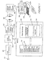
- FIG. 1 there is depicted a schematic diagram of a cochlear implant prosthesis interfaced to a processing means in the form of microcomputer 250.
- the cochlear implant prosthesis functions as follows.
- a microphone 211 monitors ambient sounds, for example speech, and converts those sounds to electrical impulses.
- the audio pre-processing module 225 then performs various operations such as bandpass filtering, application of AGC and analogue to digital conversion.
- the digital signal is then analysed by the central processing unit 222 according to a speech processing strategy stored in program storage memory 228.
- the speech processing strategy determines by which electrodes the stimulations are to be delivered in order to best simulate the ambient sound by interrogating the frequency range to electrode allocation map 223 by means of bidirectional bus 252.
- the central processing unit 222 generates commands for the receiver stimulator 220 specifying the electrodes by which the stimulation is to be delivered and the amplitude and duration of the stimulation.
- the commands are encoded by the data transmitter 219 and sent via transcutaneous link 215 to the implanted receiver stimulator.
- the receiver stimulator decodes the commands and the applies stimulation via the specified electrodes thereby eliciting sound perceptions in the
- an X-ray 230 of the cochlea with implanted electrode array is produced and referred to by an operator (not shown).
- an X-ray is used in the presently described embodiment other suitable medical imaging techniques could also be used to produce the necessary images.
- the operator visualises reference lines on the X-ray relative to certain anatomical landmarks therein depicted.
- Data concerning the position of the electrode array relative to the basilar membrane is then entered into a processing means 234.
- the microcomputer runs a program which contains a model of the cochlea suitable for generating the characteristic frequency of each electrode. On the basis of the calculated characteristic frequencies a frequency range to electrode map is generated either automatically according to preset instructions or with additional input from a clinician.
- the frequency range to electrode map is then downloaded from the microcomputer 250 to the speech processor by an interface means 236.
- This means could be a serial data connection, for example an RS232 or IIC interface as is well known in the art.
- the data is then transferred to patient data storage 218 where it becomes the frequency range to electrode allocation map of the speech processor.
- the processing means which calculates the characteristic frequencies is a microcomputer and is distinct from the central processing unit 222 of the cochlear implant prosthesis.
- the calculations performed by microcomputer 250 are undertaken by the processing means of the cochlear implant speech processor 222 and the software required to calculate the characteristic frequencies stored within the cochlear implant prosthesis program storage memory 228 as characteristic frequency calculation program 217.
- the embodiment depicted in Figure 1 relies on a human operator to visually locate various landmarks on the X-ray, or other diagnostic image, and enter them into the processing means by some means such as the keyboard 232 it would also be possible to use more highly automated methods.
- the X-ray could be inserted into a scanner and pattern recognition methods used to locate the landmarks whose position would then be transferred to the processing means.
- an X-ray machine or other medical imaging equipment could be either directly, or via electronic data storage means, coupled to an image processing means interfaced to processor 234 so that no hardcopy of the X-ray or manual data entry would be required.
- the present invention is designed to be implemented after surgical implantation has been performed. It will be appreciated that variations in anatomy and in the extent of insertion of the array mean that the positioning of the electrode array will differ for each patient, and the present invention is intended to provide an accurate method of determining characteristic frequency for each implanted array.
- an X-ray (or other suitable medical image) of the cochlea is produced, preferably using the "Cochlear View” orientation of the patient's head as described by Marsh et al. (1993) and Xu, J., Xu, S.A., Clark, G.M., and Marsh, M.A. (1994), "'Cochlear View' and its application in cochlear implant patients," International Cochlear Implant, Speech and Hearing Symposium 1994, Melbourne Australia.
- Such an X-ray image is illustrated schematically in Figure 2.
- Various anatomical features can be seen, including the vestibule 2, and the tip of the superior semicircular canal 1. From this X-ray the position of the round window 5 is estimated by drawing a primary reference line 6 from the tip of the superior semicircular canal 1 through the centre of the vestibule 2. If the array was originally located by insertion through the round window 5 then the round window will lie at the intersection of line 6 and the electrode array 10.
- a further reference line 8 is drawn from the centre of the template spiral 7 perpendicular to the primary reference line 6, relative to which angle ⁇ 9 is measured, which will be described in more detail below. From the figure can also be seen individual electrodes 3, and interelectrode spacing 4 which will be assumed to be regular.
- the method used by the processor to obtain the characteristic frequency for each electrode band of the cochlear implant in the present embodiment is as follows:
- the methods and equations used to perform the calculations are as follows.
- the counting of electrodes commences from the physical start of the electrode array, outside the cochlea. If the array is fully inserted, then an alternative calculation using two tangent lines, to be described below, may be used.
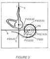
- the electrodes are counted and the number reached as the electrodes cross the primary reference line is entered (point PO in Figure 3, count of 5.5).
- the counting is continued until the electrodes have passed a number of other points on the X-ray.
- the subsequent points at which the electrodes are counted are tangents to the array, such that they are either parallel to or at right angles to the primary reference line. They are marked as P1-P6 on Figure 3.
- point P4 is the most apical point reached, and the value entered for P5 would be a default value (say, zero) to signify that the array did not reach that point. Similarly, in the general case, the value entered for the first point the array does not reach would be zero. From Figure 3, values are
- the length around the template spiral between the points where the electrode array crosses the primary reference line (P0 on Fig. 3) and the innermost tangent point (P4 in the example of Fig. 3) is calculated using a scaling factor of 1.0 in Eqns. 1 and 2 (defined below).
- the template spiral is given by Eqns 1 and 2, and the length around the spiral is calculated numerically using those equations and Eqn. 3 (defined below), which relates length along a curve to its polar coordinates (radius and angle). Note that the angles at the entry point and at all the tangent points are known from the shape of the template spiral.
- the length around the template spiral is compared with the actual length between the points 5 (PO) and P4 (in this example), as measured between electrode counts at those points.
- the distance between the centres of the electrode bands is accurately controlled during manufacture of the Cochlear Limited devices (0.75 mm), and therefore the number of bands between two points gives an accurate measure of distance.
- the scaling factor is then adjusted so that the theoretical length equals the measured length thus fitting the template spiral to the electrode spiral seen on the X-ray.
- the angle of each electrode can then be calculated from the template spiral, as the angle at point PO (5) is known and the length around the spiral from that point to the electrode is also known. This calculation is performed numerically using Eqns 1, 2 and 3.
- a reproduction of the electrode spiral may be displayed on monitor 238 based on the angle calculations performed by the program.
- the graphical representation of the electrode spiral is to allow the user to verify that the information entered is correct.
- the displayed spiral is similar to that of Figure 3.
- Fig. 3 is marked the line 8, drawn from the centre of the template spiral perpendicular to the primary reference line, relative to which angle ⁇ (item 9) is measured.
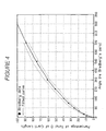
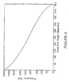
- Figure 4 illustrates percentage length along the organ of Corti plotted against angle (measured relative to Bredberg's zero). Filled circles indicate Bredberg's data and the solid curve was fitted to those data. Dashed curves are experimental variations in Bredberg's data. Once all the electrode angles have been determined, the data of Fig. 4 is used to convert each angle into a percentage of the length of the organ of Corti. This is done using Eqns. 4 and 5 (defined below), which closely approximate the results shown graphically by Bredberg and Eqn. 6 which relates the angles measured according to the present invention and the angles used by Bredberg (see below).
- the percentage of the length of the organ of Corti now enables the frequency associated with that angle (and electrode) to be calculated, using the Greenwood formula (Eqn. 7).
- the Greenwood formula describes the relationship between frequency and the site of maximal displacement of the basilar membrane, expressed as a percentage of the total length of the organ of Corti, measured from the apex.
- the frequencies obtained for the electrodes are then plotted on a frequency versus electrode graph.
- the frequency allocation of the speech processor can then be adjusted to allow for the closest frequency band allocation to the calculated electrode frequency set.
- Eqn (1) and Eqn (2) describe the radial distance from the centre (approximately the modiolus) of the template spiral as a function of angle about the centre, relative to a line drawn from the centre perpendicularly to the reference line.
- the perpendicular line is shown as 8 on Figure 3, and the angle ⁇ (in degree) is shown as item 9.
- Radius Scaling Factor * [7.9664 - 1.0252 In ⁇ - 5)]
- Radius Scaling Factor * 3.762 exp (- 0.001317 ⁇ )
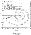
- the spiral of Eqn. 2 corresponds to the mean of 30 X-ray spirals of which 28 were for cochleostomy insertions (through the outer wall of scala tympani).
- the parameters of Eqn. 2 were established by fitting the mathematical spiral to the X-ray spirals for angle greater than 100°. Note, however, that Eqn. 1 is applicable to a round window insertion. For a cochleostomy insertion slightly different parameters would apply. As the mean values would depend slightly on surgical techniques used, it is not appropriate to specify values here. However, with respect to the present invention Eqn. 1 (as given above) is a good approximation for all cases, provided a small correction is made to the band count at the primary reference line 6, illustratively half a band.
- This general expression relates length along the spiral of the point to its polar coordinates, radius and angle (in radians).
- the centre may be estimated for a particular electrode X-ray by doing a least squares fit of the template to the digitised positions of the bands.
- the variables in this fitting process are (i) the size of the template and (ii) the x and y positions of the template. Doing this fit gave a good estimate of the centre and allowed automatic calculation of individual angles of electrodes.
- the final method as described above has the considerable advantage of requiring much less data input, in principle only two numbers, namely the electrode band counts at the principal reference line and at the most apical tangent point. Because the angle at the principal reference line crossing is Known, and the angles at the tangent points are known, these two band counts fully determine the fitting of the template to the data. The data determine the size of the template spiral, while the position of the spiral centre does not need to appear explicitly in the calculations.
- the method may be applied to other electrode arrays, for example an array that might follow the inner wall of the scala tympani, rather than the outer wall as in this case.
- the template could be a numerical relationship between radius and angle, that is, there is no need to provide an analytical expression for the relationship.
- the exponential spiral shape used here (Eqn. 2) is very suitable for the description of the shape of the inner wall of the scala tympani, for all but the most basal region of the cochlea, and would therefore be suitable for an array that followed the inner wall.
- Eqn. 1 could probably be used for the basal region.
- appropriate parameters of both Eqn. 1 and Eqn. 2 would need to be established. The parameters may be readily determined using the techniques described above.
- the inventive technique requires a knowledge of the separations between the electrodes along the array.
- the electrode separation is accurately maintained at 0.75 mm.
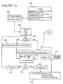
- Figured 7a, 7b, 7c illustrate one software implementation of the method described above. Such a program would be run by the processing means 234 of Figure 1.
- Input data are P o and P t , determined from the X-ray as shown in Figure 2, and other information which characterises the array.
- the last step of the process is shown in the box 362, marked END, and is to set the frequency range to electrode map 238 on the basis of the calculated characteristic frequency values in the array Freq[].
- the flowchart depicted in Figures 7a-7c is to be read on the understanding that the commands flow from figure to figure at the points marked with identical capital letters.
- Fig 7a the flowchart begins with start box 300 by which the first step is to locate the landmark points at which the electrode array crosses the primary reference line P o (item 5 of Figure 3) and the final tangential point of the array P 1 (point P4 of Figure 3). Other data concerning the total number of electrodes in the array and the spacing between them is also entered.
- the scale factor variable Scale_fact is initialised to 1.0.
- box 302 the angles ⁇ o and ⁇ f which correspond to the angular positions of P o and P f are determined from a pre-calculated table of angles such as the one described earlier in reference to equations 1 to 3.
- the remainder of the flowchart of Figure 7a is concerned with finding the length around a template spiral between the angles ⁇ o and ⁇ f and comparing this length with the actual length around the electrode array spiral between P o and P f in order to determine a scaling factor.
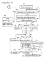
- the variable ⁇ is initialised to ⁇ o and the variable L, representing the length around the template spiral from ⁇ o to ⁇ f , to zero.
- ⁇ represents a small incremental change in ⁇ and is initialised to 0.1.
- the polar coordinates (R th ⁇ ) along the template spiral are calculated according to the equations in boxes 308 and 310 being previously described equations (1) and (2).
- the distance along the template spiral from ⁇ o to ⁇ is calculated by numerically solving the differential equation for the distance along a curve given in polar coordinates. Methods for solving such equations are standard in the art of mathematical computing and will not be discussed in detail here.
- the distance along the spiral template is accumulated in the variable L and the variable ⁇ is incremented (box 314) until it is slightly greater than ⁇ f (box 316).
- the length of the template spiral is then stored in variable Th_length (box 318).
- the number of electrode bands from P f to P o is calculated and converted to a distance by multiplying it by the InterElectrodeSpacing variable.
- the actual distance between the two landmark points P f and P o on the electrode array is stored in the variable Act_length.
- the ratio of the actual length of the cochlear electrode array spiral, between P f and P o , to the length previously calculated along the template spiral by the angle subtended by P f and P o is calculated and stored in variable Scale_fact.
- the ElectrodeCounter variable is initialised to 1 in order to commence calculation of the angular position of the first electrode.
- the bandnumber of the electrode is calculated from its electrode number. For example it can be seen with reference to Figure 3 that electrode 1 (item 13) corresponds to band 11 as there are ten non-electrode stiffening bands located basal to the first stimulating electrode. The length along the array of the first spiral to the electrode with number ElectrodeCounter is determined in box 328 by finding the number of bands between the first landmark point Po and the electrode under consideration. As an example, for the first electrode of Figure 3 the ElectrodeCounter variable is set to 1. The BandCount variable is set to 11 being the sum of the ElectrodeCounter value and the number of stiffening bands.
- the length variable is the distance of the first electrode along the cochlear electrode array and equals the product of the interelectrode spacing with, the difference of the BandCount variable (11) and the band number at which the electrode array crossed the primary reference line which was 5.5 for the example depicted in Figure 3.
- the corresponding angular position on the template spiral can then be calculated for electrode number 1. This value is calculated in similar fashion to that described with reference to the loop of Figure 7a.
- the value for ⁇ which corresponds to the postion of the electrode on the template spiral is stored in data array Ang[] at box 350.
- the angle ⁇ is related to the Bredberg angle ⁇ B as previously described.
- FIG. 7c therein is depicted a section of the flowchart in which the percentage length along the organ of Corti for each electrode is calculated from its angle n in degrees about the modiolus of the electrode as previously determined (boxes 354, 356).
- the percentage length is then used to calculate the theoretical characteristic frequency of the electrode at box 358 and the result is stored in an indexed data array Freq[].
- the program increments the ElectrodeCounter variable at box 360 and the electrode position frequencies are calculated and stored for each electrode until the condition of decision box 326 of Figure 7b is satisfied thereby signifying that the characteristic frequencies of all the electrodes have been determined.
- the final step of the procedure is depicted at box 362 by which the electrode array characteristic frequencies stored in Freq[] are used to set the Frequency Band to Electrode Map 223 of the cochlear prosthesis.
Landscapes
- Health & Medical Sciences (AREA)
- Otolaryngology (AREA)
- Engineering & Computer Science (AREA)
- Biomedical Technology (AREA)
- Nuclear Medicine, Radiotherapy & Molecular Imaging (AREA)
- Radiology & Medical Imaging (AREA)
- Life Sciences & Earth Sciences (AREA)
- Animal Behavior & Ethology (AREA)
- General Health & Medical Sciences (AREA)
- Public Health (AREA)
- Veterinary Medicine (AREA)
- Prostheses (AREA)
Claims (15)
- Vorrichtung zur Darstellung der Frequenzverteilung für einen Elektrodenplan einer kochlearen Implantat-Prothese mit einer. Elektrodenanordnung (10), wobei die Frequenzverteilung für den Elektrodenplan (223) eine Frequenzverteilung für E-lektroden-Abbildungsdaten beinhaltet und Folgendes aufweist:a) Bearbeitungsmittel (234), das derart angeordnet ist um Elektrodenpositionsdaten zu empfangen und zu verarbeiten, wobei die Elektrodenpositionsdaten zwei Passwerte (Po,Pf) beinhalten, die die Position von zumindest zwei Elektroden der Elektrodenanordnung relativ zu einer Kochlea beschreiben, wobei das Bearbeitungsmittel angeordnet ist um charakteristische Frequenzdaten zum Einsatz bei der Bestimmung einer Frequenzverteilung für die Elektrodenabbildung entsprechend einem charakteristischen Frequenzmodell zu erzeugen, worin die charakteristischen Frequenzdaten charakteristische Frequenzen der Elektroden der Elektrodenanordnung beinhaltet und die charakteristische Frequenz einer Elektrode, die mit der berechneten Frequenz der maximalen Versetzung der Basilarmembran der Kochlea korrespondiert;b) Eingabemittel (232) zur Übermittlung der Elektrodenpositionsdaten an das Bearbeitungsmittel; undc) Schnittstellenmittel (236) zur Übertragung der Frequenzverteilung für die Elektrodenabbildungsdaten an die Frequenzverteilung für den Elektrodenplan.
- Vorrichtung nach Anspruch 1, worin das Bearbeitungsmittel (234) eingerichtet ist um die Elektrodenpositionen zu bestimmen mit Bezug zu den Abmessungen der Elektrodenanordnung (10) und eine kochleare Schablone, die darin spiralförmig eingepasst ist.
- Vorrichtung nach Anspruch 1, worin die Elektrodenpositionsdaten eingerichtet sind, um von einem medizinischen Diagnosebild (230) der Elektrodenanordnung (10) abgeleitet zu werden.
- Vorrichtung nach Anspruch 3, welche weiterhin einen Scanner aufweist, der zur Erzeugung der Elektrodenpositionsdaten von einem medizinischen Diagnosebild (230) in der Form einer Hart-Kopie eingerichtet ist.
- Vorrichtung nach Anspruch 3 oder 4, worin das Bearbeitungsmittel (234) zur Ableitung der Elektrodenpositionsdaten durch Bearbeitung der Bilddaten eingerichtet ist, die ein medizinisches Diagnosebild (230) darstellen.
- Vorrichtung nach einem der vorhergehenden Ansprüche, worin das Bearbeitungsmittel (222) integral ausgebildet ist mit der kochlearen Implantat-Prothese und worin das Schnittstellenmittel (236) einen Bus zur Verbindung des Bearbeitungsmittels mit der Frequenzverteilung für den Elektrodenplan (223) aufweist.
- Verfahren zum Setzen des Frequenzbereiches für den Elektrodenplan einer kochlearen Implantat-Prothese, welches folgende Schritte beinhaltet,:a) Bestimmung zweier Passwerte (Po,Pf) unter Bezug auf eine eingesetzte Elektrodenanordnung (10), wobei die Elektrodenanordnung in einer Kochlea implantiert ist;b) Anpassen einer spiralförmigen Kochlea-Schablone an die Elektrodenanordnung entsprechend der Passwerte;c) Bestimmung der Position einer jeden Elektrode der Elektrodenanordnungsspirale relativ zu der Kochlea von der spiralförmigen Kochlea-Schablone und bekannten Abmessungen des Types der implantierten Anordnung;d) Berechnung einer charakteristischen Frequenz für jede Elektrode von der Position einer jeden Elektrode relativ zu der Kochlea entsprechend einem mathematischen Modell für besondere Frequenzcharakteristika einer Kochlea für jede der Elektroden; unde) Setzen (362) der Frequenzverteilung für den Elektrodenplan der kochlearen Implantat Prothese auf der Basis der charakteristischen Frequenzen, die in dem vorhergehenden Schritt berechnet werden.
- Verfahren nach Anspruch 7, worin die Passwerte unter Bezug auf ein medizinisches Diagnose-Bild (230) bestimmt werden indem die implantierte Elektrodenannordnung (10) und anatomische Strukturen des Innenohren sichtbar sind.
- Verfahren nach Anspruch 8, worin einer der beiden Passwerte (Po) durch die Anzahl der Elektroden bestimmt wird, die sich nach außen hin von dem runden Fenster (S) erstrecken, wobei der andere der beiden Passwerte (Pf) die Anzahl der Elektroden darstellt, die sich von dem runden Fenster zu dem äußersten Scheitelpunkt (P4) eines Satzes von geometrisch bestimmten Punkten (P0-P6) auf dem medizinischen Diagnosebild (230) erstrecken.
- Verfahren nach Anspruch 9, worin der Satz von geometrisch bestimmten Punkten (P0 - P6) solche Punkte auf der Elektrodenanordnung (10) umfasst, die sich mit einer Tangente der Elektrodenanordnung schneiden, worin die Tangente entweder parallel oder senkrecht zu einer Hauptreferenzlinie (6) verläuft, wobei die Hauptreferenzlinie durch anatomische Positionsmarken (1,2) des Innenohres bestimmt ist.
- Verfahren nach Anspruch 8, worin der Schritt (c) weiterhin aufweist:die Bestimmung des Winkels (Θ), der definiert ist durch jede Elektrode relativ zu dem berechneten Zentrum der Kochleaspirale und einer vorbestimmten Referenzlinie (8), die durch die Spirale hindurchführt; undBerechnung der prozentualen Länge entlang des Organes der Corti korrespondierend mit dem berechneten Winkel, für jede Elektrode.
- Software-Erzeugnis zur Bestimmung einer charakteristischen Frequenz für Elektroden in einer implantierten intrakochlearen Elektrodenanordnung (10) basierend auf einem medizinischen Diagnosebild (230), wobei das Erzeugnis mit Eingangsdaten bezüglich einer vorhandenen implantierten Anordnung versorgt wird:einem ersten Wert (Po), der die Anzahl der Elektroden darstellt, die sich nach außen hin durch ein rundes Fenster (5) erstrecken, welches zur Einführung der Elektrodenanordnung verwendet wird; undeinem zweiten Wert (Pf), welcher die Anzahl der Elektroden darstellt, die sich von dem runden Fenster zu dem äußersten Scheitelpunkt (P4) eines Satzes von geometrisch bestimmten Punkten (P0-P7) auf dem medizinischen Diagnosebild, bis zu dem das Bild der Anordnung reicht, erstrecken und womit der äußerste Scheitelpunkt der Punkte identifiziert wird, wobei das Erzeugnis Folgendes beinhaltet:Mittel zur Bestimmung der Position der implantierten Elektroden durch Bezug auf die Werte und auf vorbestimmte Abmessungen der Elektrodenanordnung;Mittel zur Aufnahme der Elektrodenpositionen für korrespondierende charakteristische Frequenzen; undMittel zur Ausgabe eines Satzes, welcher charakteristische Frequenzen für jede Elektrode enthält.
- Erzeugnis nach Anspruch 12, worin das Mittel zur Bestimmung der Position der implantierten Elektroden die Größe einer spiralförmigen Kochlea-Schablone mit Bezug auf eine mathematische Beschreibung der Gestalt der Koleaspirale berechnet.
- Erzeugnis nach Anspruch 13, worin das Mittel zur Bestimmung der Position der implantierten Elektroden weiterhin den Winkel (Θ) bestimmt, der gegeben ist durch jede Elektrode relativ zu dem berechneten Zentrum der Kochleaspirale und eine vorbestimmte Referenzlinie (8), die durch die Spirale hindurch ragt, und berechnet für jede Elektrode die prozentuale Länge entlang des Organes der Corti, korrespondierend mit dem berechneten Winkel.
- Erzeugnis nach Anspruch 14, worin das Mittel zur Aufnahme der Elektrodenpositionen für korrespondierende charakteristische Frequenzen die charakteristische Frequenz für jede Elektrode berechnet unter Verwendung der prozentualen Länge entlang des Organes der Corti und einer vorbestimmten Beziehung zu einer charakteristischen Frequenz.
Applications Claiming Priority (8)
| Application Number | Priority Date | Filing Date | Title |
|---|---|---|---|
| AUPN990996 | 1996-05-16 | ||
| AUPN9909/96 | 1996-05-16 | ||
| AUPN9909A AUPN990996A0 (en) | 1996-05-16 | 1996-05-16 | Method and means for calculating electrode frequency allocation |
| AUPN9953/96 | 1996-05-20 | ||
| AUPN9953A AUPN995396A0 (en) | 1996-05-20 | 1996-05-20 | Method and means for calculating electrode frequency allocation |
| AUPN995396 | 1996-05-20 | ||
| PCT/AU1997/000295 WO1997043871A1 (en) | 1996-05-16 | 1997-05-14 | Calculating electrode frequency allocation in a cochlear implant |
| US09/040,355 US6068652A (en) | 1996-05-16 | 1998-03-10 | Method and means for calculating electrode frequency allocation |
Publications (3)
| Publication Number | Publication Date |
|---|---|
| EP0906713A1 EP0906713A1 (de) | 1999-04-07 |
| EP0906713A4 EP0906713A4 (de) | 2001-01-31 |
| EP0906713B1 true EP0906713B1 (de) | 2004-10-06 |
Family
ID=27157928
Family Applications (1)
| Application Number | Title | Priority Date | Filing Date |
|---|---|---|---|
| EP97920453A Expired - Lifetime EP0906713B1 (de) | 1996-05-16 | 1997-05-14 | Bestimmung von elektrodenfrequenzverteilung in einem cochlearen implantat |
Country Status (5)
| Country | Link |
|---|---|
| US (1) | US6068652A (de) |
| EP (1) | EP0906713B1 (de) |
| JP (1) | JP2000509566A (de) |
| CA (1) | CA2254777A1 (de) |
| WO (1) | WO1997043871A1 (de) |
Cited By (1)
| Publication number | Priority date | Publication date | Assignee | Title |
|---|---|---|---|---|
| WO2016035027A1 (en) * | 2014-09-02 | 2016-03-10 | Cochlear Limited | Intra-cochlear stimulating assembly insertion |
Families Citing this family (33)
| Publication number | Priority date | Publication date | Assignee | Title |
|---|---|---|---|---|
| US6289247B1 (en) * | 1998-06-02 | 2001-09-11 | Advanced Bionics Corporation | Strategy selector for multichannel cochlear prosthesis |
| US8285382B2 (en) | 2000-08-21 | 2012-10-09 | Cochlear Limited | Determining stimulation signals for neural stimulation |
| US9008786B2 (en) | 2000-08-21 | 2015-04-14 | Cochlear Limited | Determining stimulation signals for neural stimulation |
| AUPQ952800A0 (en) | 2000-08-21 | 2000-09-14 | Cochlear Limited | Power efficient electrical stimulation |
| US7822478B2 (en) | 2000-08-21 | 2010-10-26 | Cochlear Limited | Compressed neural coding |
| AUPR604801A0 (en) | 2001-06-29 | 2001-07-26 | Cochlear Limited | Multi-electrode cochlear implant system with distributed electronics |
| US7292891B2 (en) * | 2001-08-20 | 2007-11-06 | Advanced Bionics Corporation | BioNet for bilateral cochlear implant systems |
| EP1338301A1 (de) | 2002-02-21 | 2003-08-27 | Paul J. M. Govaerts | Verfahren zur automatischen Kalibrierung eines cochlearen Implantates, erhaltenes cochleares Implantat und Rechnerprogrammen dafür |
| US7251530B1 (en) | 2002-12-11 | 2007-07-31 | Advanced Bionics Corporation | Optimizing pitch and other speech stimuli allocation in a cochlear implant |
| US7292892B2 (en) * | 2003-11-21 | 2007-11-06 | Advanced Bionics Corporation | Methods and systems for fitting a cochlear implant to a patient |
| KR100568469B1 (ko) | 2004-06-28 | 2006-04-07 | 한양대학교 산학협력단 | 잡음 제거 기능을 구비한 인공 와우 및 잡음 제거 방법 |
| WO2008031169A1 (en) * | 2006-09-14 | 2008-03-20 | Cochlear Limited | Medical implant configuration method |
| US8894697B2 (en) * | 2011-07-22 | 2014-11-25 | Lockheed Martin Corporation | Optical pulse-width modulation used in an optical-stimulation cochlear implant |
| US8160328B2 (en) | 2008-01-31 | 2012-04-17 | Medtronic, Inc. | Characterization of electrical stimulation electrodes using post-implant imaging |
| KR101003379B1 (ko) * | 2008-03-25 | 2010-12-22 | [주]이어로직코리아 | 이명 탐색/치료 방법 및 시스템 |
| US20090287277A1 (en) * | 2008-05-19 | 2009-11-19 | Otologics, Llc | Implantable neurostimulation electrode interface |
| WO2010025504A1 (en) * | 2008-09-02 | 2010-03-11 | The University Of Queensland | Improvements for cochlear implants |
| US20100069997A1 (en) * | 2008-09-16 | 2010-03-18 | Otologics, Llc | Neurostimulation apparatus |
| US8995731B2 (en) | 2008-11-26 | 2015-03-31 | Medtronic, Inc. | Image-based characterization of implanted medical leads |
| US9044588B2 (en) * | 2009-04-16 | 2015-06-02 | Cochlear Limited | Reference electrode apparatus and method for neurostimulation implants |
| US20100318167A1 (en) * | 2009-04-17 | 2010-12-16 | Otologics, Llc | Neurostimulation electrode array and method of manufacture |
| US8771166B2 (en) | 2009-05-29 | 2014-07-08 | Cochlear Limited | Implantable auditory stimulation system and method with offset implanted microphones |
| US20110093051A1 (en) | 2009-10-21 | 2011-04-21 | Medtronic, Inc. | Assignment and manipulation of implantable leads in different anatomical regions with image background |
| US9814885B2 (en) | 2010-04-27 | 2017-11-14 | Medtronic, Inc. | Stimulation electrode selection |
| US8515540B2 (en) | 2011-02-24 | 2013-08-20 | Cochlear Limited | Feedthrough having a non-linear conductor |
| US8406890B2 (en) | 2011-04-14 | 2013-03-26 | Medtronic, Inc. | Implantable medical devices storing graphics processing data |
| US9572981B2 (en) * | 2012-04-03 | 2017-02-21 | Vanderbilt University | Methods and systems for customizing cochlear implant stimulation and applications of same |
| US20160059014A1 (en) | 2014-09-02 | 2016-03-03 | Benjamin Peter Johnston | Event Detection In An Implantable Auditory Prosthesis |
| US11071869B2 (en) | 2016-02-24 | 2021-07-27 | Cochlear Limited | Implantable device having removable portion |
| US10743114B2 (en) * | 2016-11-22 | 2020-08-11 | Cochlear Limited | Dynamic stimulus resolution adaption |
| WO2020021388A1 (en) * | 2018-07-25 | 2020-01-30 | Cochlear Limited | Individualized adaptation of medical prosthesis settings |
| WO2021041466A1 (en) * | 2019-08-26 | 2021-03-04 | Vanderbilt University | Patient customized electro-neural interface models for model-based cochlear implant programming and applications of same |
| DK3928828T3 (da) * | 2020-06-22 | 2023-07-03 | Oticon Medical As | Harmonisk tildeling af cochleære implantatfrekvenser |
Family Cites Families (7)
| Publication number | Priority date | Publication date | Assignee | Title |
|---|---|---|---|---|
| US4400590A (en) * | 1980-12-22 | 1983-08-23 | The Regents Of The University Of California | Apparatus for multichannel cochlear implant hearing aid system |
| US4536844A (en) * | 1983-04-26 | 1985-08-20 | Fairchild Camera And Instrument Corporation | Method and apparatus for simulating aural response information |
| US4918745A (en) * | 1987-10-09 | 1990-04-17 | Storz Instrument Company | Multi-channel cochlear implant system |
| US5061282A (en) * | 1989-10-10 | 1991-10-29 | Jacobs Jared J | Cochlear implant auditory prosthesis |
| WO1994010820A1 (en) * | 1992-11-02 | 1994-05-11 | Goldstein Julius L | Electronic simulator of non-linear and active cochlear signal processing |
| US5601617A (en) * | 1995-04-26 | 1997-02-11 | Advanced Bionics Corporation | Multichannel cochlear prosthesis with flexible control of stimulus waveforms |
| AUPN533195A0 (en) * | 1995-09-07 | 1995-10-05 | Cochlear Pty. Limited | Derived threshold and comfort level for auditory prostheses |
-
1997
- 1997-05-14 CA CA002254777A patent/CA2254777A1/en not_active Abandoned
- 1997-05-14 EP EP97920453A patent/EP0906713B1/de not_active Expired - Lifetime
- 1997-05-14 JP JP9527138A patent/JP2000509566A/ja active Pending
- 1997-05-14 WO PCT/AU1997/000295 patent/WO1997043871A1/en not_active Ceased
-
1998
- 1998-03-10 US US09/040,355 patent/US6068652A/en not_active Expired - Lifetime
Cited By (5)
| Publication number | Priority date | Publication date | Assignee | Title |
|---|---|---|---|---|
| WO2016035027A1 (en) * | 2014-09-02 | 2016-03-10 | Cochlear Limited | Intra-cochlear stimulating assembly insertion |
| US9597503B2 (en) | 2014-09-02 | 2017-03-21 | Cochlear Limited | Intra-cochlear stimulating assembly insertion |
| CN106794344A (zh) * | 2014-09-02 | 2017-05-31 | 耳蜗有限公司 | 耳蜗内刺激组件插入 |
| CN106794344B (zh) * | 2014-09-02 | 2020-10-20 | 科利耳有限公司 | 耳蜗内刺激组件插入 |
| EP3978068A1 (de) * | 2014-09-02 | 2022-04-06 | Cochlear Limited | Einsetzen einer anordnung zur intracochlearen stimulierung |
Also Published As
| Publication number | Publication date |
|---|---|
| JP2000509566A (ja) | 2000-07-25 |
| WO1997043871A1 (en) | 1997-11-20 |
| EP0906713A1 (de) | 1999-04-07 |
| EP0906713A4 (de) | 2001-01-31 |
| US6068652A (en) | 2000-05-30 |
| CA2254777A1 (en) | 1997-11-20 |
Similar Documents
| Publication | Publication Date | Title |
|---|---|---|
| EP0906713B1 (de) | Bestimmung von elektrodenfrequenzverteilung in einem cochlearen implantat | |
| Cohen et al. | Improved and simplified methods for specifying positions of the electrode bands of a cochlear implant array | |
| Stakhovskaya et al. | Frequency map for the human cochlear spiral ganglion: implications for cochlear implants | |
| Rebscher et al. | Considerations for the design of future cochlear implant electrode arrays: Electrode array stiffness, size and depth of insertion | |
| Rader et al. | Place dependent stimulation rates improve pitch perception in cochlear implantees with single-sided deafness | |
| Noble et al. | Clinical evaluation of an image-guided cochlear implant programming strategy | |
| Helpard et al. | An approach for individualized cochlear frequency mapping determined from 3D synchrotron radiation phase-contrast imaging | |
| US8086319B2 (en) | Cochlear implant fitting | |
| Marsh et al. | Radiologic evaluation of multichannel intracochlear implant insertion depth | |
| EP3978068B1 (de) | Einsetzen einer anordnung zur intracochlearen stimulierung | |
| US7206640B1 (en) | Method and system for generating a cochlear implant program using multi-electrode stimulation to elicit the electrically-evoked compound action potential | |
| Skinner et al. | Determination of the position of nucleus cochlear implant electrodes in the inner ear | |
| US9320887B2 (en) | Objective allocation of implant electrode bands based on excitation spread | |
| Dorman et al. | An electric frequency-to-place map for a cochlear implant patient with hearing in the nonimplanted ear | |
| US20180161578A1 (en) | Device and Method for Electric Stimulation with the Aid of a Cochlea-Implant | |
| Cohen et al. | Psychophysical measures in patients fitted with Contour™ and straight Nucleus electrode arrays | |
| US20080221640A1 (en) | Multi-electrode stimulation to elicit electrically-evoked compound action potential | |
| US9320896B2 (en) | Accelerated fitting of cochlear implants based on current spread | |
| US9775999B2 (en) | System comprising a cochlear stimulation device and a second hearing stimulation device and a method for adjustment according to a response to combined stimulation | |
| Wang et al. | Unwrapping cochlear implants by spiral CT | |
| Busby et al. | Electrode discrimination by early-deafened subjects using the cochlear limited multiple-electrode cochlear implant | |
| AU709374B2 (en) | Calculating electrode frequency allocation in a cochlear implant | |
| CN117379685A (zh) | 人工耳蜗调频方法、装置及其非暂态计算机可读取媒体 | |
| CN111084931B (zh) | 植入式脊髓刺激系统及其信息记录和调整方法 | |
| CN113940735A (zh) | 一种骶骨神经穿刺路径模拟规划系统及装置 |
Legal Events
| Date | Code | Title | Description |
|---|---|---|---|
| PUAI | Public reference made under article 153(3) epc to a published international application that has entered the european phase |
Free format text: ORIGINAL CODE: 0009012 |
|
| 17P | Request for examination filed |
Effective date: 19981109 |
|
| AK | Designated contracting states |
Kind code of ref document: A1 Designated state(s): DE FR GB |
|
| A4 | Supplementary search report drawn up and despatched |
Effective date: 20001215 |
|
| AK | Designated contracting states |
Kind code of ref document: A4 Designated state(s): DE FR GB |
|
| 17Q | First examination report despatched |
Effective date: 20021105 |
|
| GRAP | Despatch of communication of intention to grant a patent |
Free format text: ORIGINAL CODE: EPIDOSNIGR1 |
|
| GRAS | Grant fee paid |
Free format text: ORIGINAL CODE: EPIDOSNIGR3 |
|
| GRAA | (expected) grant |
Free format text: ORIGINAL CODE: 0009210 |
|
| GRAL | Information related to payment of fee for publishing/printing deleted |
Free format text: ORIGINAL CODE: EPIDOSDIGR3 |
|
| GRAS | Grant fee paid |
Free format text: ORIGINAL CODE: EPIDOSNIGR3 |
|
| AK | Designated contracting states |
Kind code of ref document: B1 Designated state(s): DE FR GB |
|
| PG25 | Lapsed in a contracting state [announced via postgrant information from national office to epo] |
Ref country code: FR Free format text: LAPSE BECAUSE OF NON-PAYMENT OF DUE FEES Effective date: 20041006 |
|
| REG | Reference to a national code |
Ref country code: GB Ref legal event code: FG4D |
|
| REF | Corresponds to: |
Ref document number: 69731087 Country of ref document: DE Date of ref document: 20041111 Kind code of ref document: P |
|
| PGFP | Annual fee paid to national office [announced via postgrant information from national office to epo] |
Ref country code: GB Payment date: 20050726 Year of fee payment: 9 |
|
| PLBE | No opposition filed within time limit |
Free format text: ORIGINAL CODE: 0009261 |
|
| 26N | No opposition filed |
Effective date: 20050707 |
|
| EN | Fr: translation not filed | ||
| PG25 | Lapsed in a contracting state [announced via postgrant information from national office to epo] |
Ref country code: DE Free format text: LAPSE BECAUSE OF NON-PAYMENT OF DUE FEES Effective date: 20051201 |
|
| PG25 | Lapsed in a contracting state [announced via postgrant information from national office to epo] |
Ref country code: GB Free format text: LAPSE BECAUSE OF NON-PAYMENT OF DUE FEES Effective date: 20060514 |
|
| GBPC | Gb: european patent ceased through non-payment of renewal fee |
Effective date: 20060514 |