EP0906538B1 - A process for continuous preparation of pipe sections with foil - Google Patents
A process for continuous preparation of pipe sections with foil Download PDFInfo
- Publication number
- EP0906538B1 EP0906538B1 EP97927015A EP97927015A EP0906538B1 EP 0906538 B1 EP0906538 B1 EP 0906538B1 EP 97927015 A EP97927015 A EP 97927015A EP 97927015 A EP97927015 A EP 97927015A EP 0906538 B1 EP0906538 B1 EP 0906538B1
- Authority
- EP
- European Patent Office
- Prior art keywords
- foil
- shaped member
- process according
- shaped
- layer
- Prior art date
- Legal status (The legal status is an assumption and is not a legal conclusion. Google has not performed a legal analysis and makes no representation as to the accuracy of the status listed.)
- Expired - Lifetime
Links
- 239000011888 foil Substances 0.000 title claims abstract description 136
- 238000000034 method Methods 0.000 title claims abstract description 52
- 230000008569 process Effects 0.000 title claims abstract description 43
- 238000002360 preparation method Methods 0.000 title claims abstract description 8
- 238000007493 shaping process Methods 0.000 claims abstract description 39
- 239000010410 layer Substances 0.000 claims description 18
- 239000000853 adhesive Substances 0.000 claims description 15
- 230000001070 adhesive effect Effects 0.000 claims description 15
- 229910052751 metal Inorganic materials 0.000 claims description 9
- 239000002184 metal Substances 0.000 claims description 9
- 238000004519 manufacturing process Methods 0.000 claims description 6
- 239000012943 hotmelt Substances 0.000 claims description 4
- 239000012790 adhesive layer Substances 0.000 claims description 3
- 230000000717 retained effect Effects 0.000 claims description 3
- 239000004411 aluminium Substances 0.000 claims description 2
- 229910052782 aluminium Inorganic materials 0.000 claims description 2
- XAGFODPZIPBFFR-UHFFFAOYSA-N aluminium Chemical compound [Al] XAGFODPZIPBFFR-UHFFFAOYSA-N 0.000 claims description 2
- 229920001296 polysiloxane Polymers 0.000 claims description 2
- 238000009413 insulation Methods 0.000 abstract description 4
- 239000012774 insulation material Substances 0.000 description 9
- 239000000463 material Substances 0.000 description 8
- 229910052500 inorganic mineral Inorganic materials 0.000 description 6
- 239000011707 mineral Substances 0.000 description 6
- 230000008901 benefit Effects 0.000 description 5
- 239000000835 fiber Substances 0.000 description 5
- 239000003292 glue Substances 0.000 description 5
- 238000003466 welding Methods 0.000 description 4
- 230000002093 peripheral effect Effects 0.000 description 3
- 239000011248 coating agent Substances 0.000 description 2
- 238000000576 coating method Methods 0.000 description 2
- 238000001816 cooling Methods 0.000 description 2
- 238000005520 cutting process Methods 0.000 description 2
- 238000010438 heat treatment Methods 0.000 description 2
- 239000004033 plastic Substances 0.000 description 2
- 229920003023 plastic Polymers 0.000 description 2
- -1 polytetrafluoroethylene Polymers 0.000 description 2
- 229920001343 polytetrafluoroethylene Polymers 0.000 description 2
- 239000004810 polytetrafluoroethylene Substances 0.000 description 2
- 230000001105 regulatory effect Effects 0.000 description 2
- 230000037303 wrinkles Effects 0.000 description 2
- 239000004698 Polyethylene Substances 0.000 description 1
- 229910000831 Steel Inorganic materials 0.000 description 1
- NIXOWILDQLNWCW-UHFFFAOYSA-N acrylic acid group Chemical group C(C=C)(=O)O NIXOWILDQLNWCW-UHFFFAOYSA-N 0.000 description 1
- 239000002390 adhesive tape Substances 0.000 description 1
- 238000005452 bending Methods 0.000 description 1
- 230000033228 biological regulation Effects 0.000 description 1
- 230000015572 biosynthetic process Effects 0.000 description 1
- 239000004568 cement Substances 0.000 description 1
- 238000011437 continuous method Methods 0.000 description 1
- 230000001276 controlling effect Effects 0.000 description 1
- 238000013016 damping Methods 0.000 description 1
- 238000009792 diffusion process Methods 0.000 description 1
- 239000000945 filler Substances 0.000 description 1
- 239000011521 glass Substances 0.000 description 1
- 239000001963 growth medium Substances 0.000 description 1
- 230000006872 improvement Effects 0.000 description 1
- 230000006698 induction Effects 0.000 description 1
- 230000001939 inductive effect Effects 0.000 description 1
- 230000007246 mechanism Effects 0.000 description 1
- 150000002739 metals Chemical class 0.000 description 1
- ZLANVVMKMCTKMT-UHFFFAOYSA-N methanidylidynevanadium(1+) Chemical class [V+]#[C-] ZLANVVMKMCTKMT-UHFFFAOYSA-N 0.000 description 1
- 239000011490 mineral wool Substances 0.000 description 1
- 230000000149 penetrating effect Effects 0.000 description 1
- 239000006223 plastic coating Substances 0.000 description 1
- 229920000573 polyethylene Polymers 0.000 description 1
- 239000011148 porous material Substances 0.000 description 1
- 230000005855 radiation Effects 0.000 description 1
- 230000009467 reduction Effects 0.000 description 1
- 230000002787 reinforcement Effects 0.000 description 1
- 230000000979 retarding effect Effects 0.000 description 1
- 239000011435 rock Substances 0.000 description 1
- 238000007789 sealing Methods 0.000 description 1
- 239000002893 slag Substances 0.000 description 1
- 239000007779 soft material Substances 0.000 description 1
- 239000007787 solid Substances 0.000 description 1
- 238000005507 spraying Methods 0.000 description 1
- 239000010959 steel Substances 0.000 description 1
- 229920002994 synthetic fiber Polymers 0.000 description 1
- 229920001169 thermoplastic Polymers 0.000 description 1
- 239000004416 thermosoftening plastic Substances 0.000 description 1
- 230000007704 transition Effects 0.000 description 1
- XLYOFNOQVPJJNP-UHFFFAOYSA-N water Substances O XLYOFNOQVPJJNP-UHFFFAOYSA-N 0.000 description 1
Images
Classifications
-
- B—PERFORMING OPERATIONS; TRANSPORTING
- B29—WORKING OF PLASTICS; WORKING OF SUBSTANCES IN A PLASTIC STATE IN GENERAL
- B29C—SHAPING OR JOINING OF PLASTICS; SHAPING OF MATERIAL IN A PLASTIC STATE, NOT OTHERWISE PROVIDED FOR; AFTER-TREATMENT OF THE SHAPED PRODUCTS, e.g. REPAIRING
- B29C63/00—Lining or sheathing, i.e. applying preformed layers or sheathings of plastics; Apparatus therefor
- B29C63/02—Lining or sheathing, i.e. applying preformed layers or sheathings of plastics; Apparatus therefor using sheet or web-like material
- B29C63/04—Lining or sheathing, i.e. applying preformed layers or sheathings of plastics; Apparatus therefor using sheet or web-like material by folding, winding, bending or the like
- B29C63/06—Lining or sheathing, i.e. applying preformed layers or sheathings of plastics; Apparatus therefor using sheet or web-like material by folding, winding, bending or the like around tubular articles
- B29C63/065—Lining or sheathing, i.e. applying preformed layers or sheathings of plastics; Apparatus therefor using sheet or web-like material by folding, winding, bending or the like around tubular articles continuously
-
- F—MECHANICAL ENGINEERING; LIGHTING; HEATING; WEAPONS; BLASTING
- F16—ENGINEERING ELEMENTS AND UNITS; GENERAL MEASURES FOR PRODUCING AND MAINTAINING EFFECTIVE FUNCTIONING OF MACHINES OR INSTALLATIONS; THERMAL INSULATION IN GENERAL
- F16L—PIPES; JOINTS OR FITTINGS FOR PIPES; SUPPORTS FOR PIPES, CABLES OR PROTECTIVE TUBING; MEANS FOR THERMAL INSULATION IN GENERAL
- F16L59/00—Thermal insulation in general
- F16L59/10—Bandages or covers for the protection of the insulation, e.g. against the influence of the environment or against mechanical damage
-
- F—MECHANICAL ENGINEERING; LIGHTING; HEATING; WEAPONS; BLASTING
- F16—ENGINEERING ELEMENTS AND UNITS; GENERAL MEASURES FOR PRODUCING AND MAINTAINING EFFECTIVE FUNCTIONING OF MACHINES OR INSTALLATIONS; THERMAL INSULATION IN GENERAL
- F16L—PIPES; JOINTS OR FITTINGS FOR PIPES; SUPPORTS FOR PIPES, CABLES OR PROTECTIVE TUBING; MEANS FOR THERMAL INSULATION IN GENERAL
- F16L59/00—Thermal insulation in general
- F16L59/14—Arrangements for the insulation of pipes or pipe systems
Definitions
- the present invention relates to a process for the preparation of a shaped member being slitted in the longitudinal direction and having a foil covering on its outer side, wherein an elongated, cylindrical, slitted shaped member with an axial, cylindrical cavity is provided with a similarly slitted covering of foil on the cylindrical outer surface.
- a pipe section typically consists of an elongated, cylindrical shaped member with an annular cavity being concentric with the longitudinal axis.
- a pipe section forms a hollow cylinder which usually is provided with a slit. By opening the slit, the pipe section can be mounted sideways on a pipe and subsequently be closed so as to form a casing around the pipe.
- the slit may optionally be closed with tape or the like.
- Pipe sections are available with varying diameters and in shortenable, combinable lengths which can be adapted to the actual need.
- pipe sections are used for insulating pipings, e.g. for reasons of energy economy, fire safety and noise, and are thus often made from the known insulation materials, such as foamable synthetic material or mineral fibre.
- insulation materials such as foamable synthetic material or mineral fibre.
- such pipe sections are typically soft or porous at the surface, and mineral fibre pipe sections in particular exhibit a coarse and uneven surface.
- DE 27 24 147 C2 discloses a process for the preparation of pipe sections covered with metal foil, wherein a slitted pipe section, preferably of mineral fibres, is covered peripherally with a sheet of metal foil which is rolled onto the pipe section from one slit edge to the other, the metal foil in the zones along and immediately adjacent to the slit edges of the pipe section being provided with adhesive, and the foil having a excess portion which extends beyond the slit, which excess portion is coated with adhesive.
- Such a method for peripheral covering of pipe sections with a foil is slow and complicated.
- the pipe section Before the rolling-on is started, the pipe section must be positioned and oriented with one slit edge over the front edge of the foil sheet.
- the rolling-on necessarily entails that the pipe section acts properly as shaping instrument towards the foil.
- the tensioning of the foil around the pipe section causes peripheral stresses in the foil, which tension it around the pipe section, which is undesirable in connection with mineral fibre pipe sections, as the unevennesses in the surface of the pipe section can be fully reflected in the form of unevennesses in the foil.
- the width of the foil sheet must furthermore match the length of the pipe section, which makes the method less expedient in production lines for the preparation of pipe sections with varying lengths, or optionally in endless form.
- US-A-3 259 533 discloses a method and an apparatus for wrapping a pipe being advanced in insulation material. According to the method, a pipe is advanced axially and covered with sheet of insulation material in the longitudinal direction. The insulation material is pressed against the pipe by passage through a funnel-shaped shaping tool, and subsequently it is wound with threads for retaining the sheet formed insulation material to the pipe.
- the said specification also describes the possibility of spraying a plastic material on the assembly so as to obtain a plastic coating.
- DE 1 924 971 C2 discloses a method for continuous preparation and positioning of a covering on an endless pipe.
- the pipe is advanced axially, and is provided with a layer of insulation material.
- a shaping tool By means of a shaping tool, a tubular covering is subsequently formed from a plane foil around the insulation layer.
- the tubular foil covering is welded together by means of a welding device.
- a preformed shaped member is advanced axially as an endless string in a production line, that an endless web of plane foil is advanced to the same production line, that by using shaping tools, the foil is shaped to an approximately tubular shape with a longitudinally extending slit and surrounding the shaped member, that the tubular diameter of the foil is gradually reduced while maintaining the axial tension until the foil is in contact with the outer side of the shaped member, and that the foil is surface adhered to the shaped member.
- the invention is based on the discovery that by imparting tubular shape to the plane foil without using the shaped member as shaping instrument, by using discrete, dimensionally stable shaping tools, and by subsequently bringing the foil with the thus formed tubular shape into contact with the shaping tool, it is possible to avoid formation of wrinkles, bulges, cracks or holes in the foil.
- the foil By forming the foil to a tubular shape using discrete shaping tools, it is thus avoided that the foil is pressed against the shaping tool during the shaping.
- shaped members of soft and porous materials can be covered with a foil without the shaped member getting deformed.
- any unevennesses on the surface of the shaped member have insignificant influence on the appearance of the foil, just as friction, due to offsetting between pipe section and foil in the shaping process, essentially can be avoided, and the resulting damages be minimized.
- the orientation of the slit of the shaped member and the positioning of the foil around the shaped member can be controlled independently. Since both parts are advanced axially and without rotation or lateral offsetting in the process according to the invention, the foil can with high precision be made to abut on the edge of the slit.
- the orientation of the slit of the shaped member is controlled - by using control means.
- control means may comprise means which engage with the slit of the shaped member.
- the plane foil is shaped to tubular shape in an initial step by passing through an annular shaping tool.
- the plane foil is shaped to tubular shape in an initial step by passing on the outer side of an annular shaping tool.
- the initial shaping of the foil to approximately tubular shape may either be performed by letting the foil pass through a dimensionally stable shaping tool having an approximately circular hole, or by letting the foil be shaped around a dimensionally stable, approximately circular shaping tool, or by using a combination of such shaping tools.
- the reduction of the tubular diameter of the foil is preferably performed by letting the foil pass through another dimensionally stable shaping tool having a circular hole, the diameter of which hole is of a size which allows passage of the shaped member and the foil in such a way that they are precisely brought into contact with each other.
- the foil may also or alternatively be brought into immediate contact with the shaped member or gently be held against the member by means of brushes or bristles.
- the foil is retained in position in relation to one or more of the shaping tools in that they are provided with means for generating an overpressure or underpressure between shaping tool and foil.
- Overpressure and underpressure can be used for controlling the foil in relation to the shaping tools. In connection with the shaping, it can thus be ensured that the foil is kept free of contact with the shaped member prior to the fixation thereon.
- one or more of the shaping tools are provided with a low-friction surface on the surface facing the foil.
- a low-friction surface may e.g. be in the form of a coating of polytetrafluoroethylene (PTFE) or certain types of metals, e.g. steel with vanadium carbides inserted on the surface according to the TDP-process (Toyota Diffusion Process).
- PTFE polytetrafluoroethylene
- TDP-process Toyota Diffusion Process
- a friction-reducing coating on the shaping tools can be used to cause the friction between shaping tools and foil to be reduced, and in order thereby to avoid an unintended heating of the foil and/or the shaping tools.
- an adhesive In order to provide the durable adhesion between the shaped member and the foil, use may be made of an adhesive.
- the adhesive may e.g. be applied onto the foil or the shaped member prior to the covering, or the adhesive may be applied as a step in the process.
- a foil and/or a shaped member comprising a zone with a layer of adhesive, a layer of hot melt, or a weldable zone, are used.
- the weldable zone or hot melt is activated by means provided with a heat source in order to provide interfixation between foil and shaped member.
- the heat may be supplied by means of hot air, infrared radiation, induction, a burner, and/or any other suitable means for supplying or inducing heat.
- the foil may be gently held against the shaped member by means of brushes or bristles.
- the foil and/or the shaped member are applied with a layer of adhesive prior to being brought into contact with each other in order to provide an interfixation.
- a foil having a width which is larger than the circumference of the shaped member for covering thereof, and the foil is positioned in such a way that the excess portion extends outwardly from one of the slit edges in relation to the axis of the shaped member.
- the excess foil portion may serve as an efficient closing mechanism for sealing the shaped member after mounting thereof.
- the excess foil portion may serve as an efficient closing mechanism for sealing the shaped member after mounting thereof.
- the excess foil portion has been or is provided with a layer of adhesive.
- the adhesive layer may e.g. be a layer of double-adhesive tape.
- the adhesive layer of the excess foil portion has been or is provided with a strippable cover, e.g. in the form of silicone paper.
- the foil is advanced by a pull in the excess portion of the foil by using advancing means, such as rolls or friction bands.
- the foil covered pipe section may advantageously also be conveyed or guided by means of conveying bands and/or rolls placed on each opposite side of the pipe section at the point where the foil is advanced by a pull in the excess portion of the foil.
- the foil covered pipe section may at this point be unsupported underneath, and merely be held in place by the advancing and/or guiding means.
- the direction of pull of the advancing means can be angular in relation to the axial direction of movement of the shaped member.
- the extension of the foil flap preferably constituted by the excess portion of the foil, can be regulated up or down depending upon whether the direction of pull has an upwardly or downwardly directed angle in relation to the axial direction of advance of the shaped member.
- the advantage is additionally achieved that the peripheral position of the foil in relation to the shaped member can be adjusted.
- the shaped member is covered with a foil having a layer of metal, preferably aluminium.
- Foils comprising a layer of metal, or foils essentially made of metal, exhibit better fire protection property than e.g. polymeric materials. Consequently, these foils are particularly suitable for covering shaped members which are to be mounted on pipes in surroundings in which there is or may be risk of fire.
- the said foils are typically more rigid than e.g. polymeric foils, and furthermore particularly sensitive to deformation due to bending, twisting, or other impact. Consequently, it is in particular an advantage of the process according to the invention that such foils can be shaped essentially without the shaped member as support.
- the invention also relates to the pipe sections covered with foil which are obtained by cutting off final lengths of the endless string of pipe sections prepared by the process according to the invention.
- a slitted shaped member essentially means a non-covered, tubular member consisting of an insulation material and being provided with a single slit for sideways mounting on a pipe.
- covering of shaped members composed of two semi-cylinders e.g. as disclosed in WO97/01006 Rockwool International, is also within the scope of the present invention, just as the process according to the invention can be used on whole pipes which are slitted simultaneously with the covering, or optionally in a later step.
- the expression pipe section essentially comprises cut-off lengths of shaped members of insulation material with or without a foil covering.
- Pipe sections which advantageously may be covered with a foil in accordance with the process according to the invention, can be made of any material suitable for preparation of prefabricated pipe sections.
- the advantages according to the invention are achieved by using pipe sections which are made of man-made mineral fibres, e.g. glass, rock and/or slag fibres, such as those which are used in plates, sheets, pipes and differently shaped products for thermal insulation, fire retarding purposes, noise damping, or noise regulation, or for fibre reinforcement of cement and plastic materials or other materials, or as filler, or as growth medium for plants.
- Mineral fibre pipe sections provided with a metal foil are particularly suitable for use in environments in which there is or may be risk of fire. Consequently, it is particularly attractive by the process according to the invention that these products can be prepared without the problems mentioned in the preamble.
- the pipe sections according to the invention are suitable for insulating both cold and hot pipes.
- adhesive comprises adhesives and adhesive components in the form of acrylic glue, water based glue, close contact glue, two-pack glue, and any other glue, adhesive or tape which is capable of providing the desired interfixation between pipe section and foil.
- weldable zone relates to a zone consisting of thermoplastic polymeric material or the like, where this material, by using a heat source, temporarily can be brought into molten state, in which it can adhere to a body, and in which, following cooling, it again undergoes transition to solid form while still adhering to the body.
- a weldable zone may e.g. consist of a layer of polyethylene.
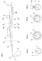
- FIG. 1 it is seen how a plane foil 1 with laminated welding layer is pulled by a supply roll 2 over a control roller 3, and how individual non-covered pipe sections in the form of shaped members 4 consisting of insulation material are positioned axially end-to-end on top of the foil web or optionally on a chute not shown in any detail, and are advanced by advancing means 5 comprising a chain with generatrices.
- the shaped members 4 being positioned axially end-to-end are hereby advanced in close succession so as to essentially appear as an endless string.
- the foil web is gradually shaped from linear cross-section (not shown) via the roll 3, over an open U-shape, as shown in Fig. 2, over the approximately tubular shape, as shown in Fig. 3, to tubular shape in immediate contact with the outer surface of the shaped member, as shown in Fig. 4.
- the shaping tool 6 (see Fig. 3) is provided with a slit through which the excess portion of the foil extends. From here the foil passes through a shaping tool with a heat source 7, (see Fig. 4), which brings the foil into immediate contact with the outer surface of the shaped member and activates the welding layer of the foil. From here the shaped member and the foil are passed through a cooling device 8, which ensures rapid curing of the welding layer so as to provide durable bonding of the foil to the outer surface of the shaped member.
- the foil is advanced while being stretched by a pull in the excess portion by using advancing means 9, (see fig. 5), comprising two movable, endless friction bands which squeeze around the excess portion of the foil, and by advancing the foremost end using the drive means 10 which comprises two movable endless friction bands which support the endless string of foil covered shaped members.
- the endless string may be divided into final lengths of pipe sections by using the cutting device 11.
- the tensioning of the foil may optionally be regulated by decelerating the roll 2, just as harmonization of the rate of the advancing means 5 and 9 and the drive means 10 can be controlled by means of not shown control units.
Landscapes
- Engineering & Computer Science (AREA)
- General Engineering & Computer Science (AREA)
- Mechanical Engineering (AREA)
- Manufacturing & Machinery (AREA)
- Laminated Bodies (AREA)
- Shaping Of Tube Ends By Bending Or Straightening (AREA)
- Lining Or Joining Of Plastics Or The Like (AREA)
- Treatment Of Fiber Materials (AREA)
Applications Claiming Priority (3)
| Application Number | Priority Date | Filing Date | Title |
|---|---|---|---|
| DK68696 | 1996-06-20 | ||
| DK68696 | 1996-06-20 | ||
| PCT/DK1997/000264 WO1997048942A1 (en) | 1996-06-20 | 1997-06-18 | A process for continuous preparation of pipe sections with foil |
Publications (2)
| Publication Number | Publication Date |
|---|---|
| EP0906538A1 EP0906538A1 (en) | 1999-04-07 |
| EP0906538B1 true EP0906538B1 (en) | 2000-05-17 |
Family
ID=8096391
Family Applications (1)
| Application Number | Title | Priority Date | Filing Date |
|---|---|---|---|
| EP97927015A Expired - Lifetime EP0906538B1 (en) | 1996-06-20 | 1997-06-18 | A process for continuous preparation of pipe sections with foil |
Country Status (7)
| Country | Link |
|---|---|
| EP (1) | EP0906538B1 (pl) |
| AT (1) | ATE193114T1 (pl) |
| AU (1) | AU3166297A (pl) |
| DE (1) | DE69702060T2 (pl) |
| ES (1) | ES2146099T3 (pl) |
| PL (1) | PL184940B1 (pl) |
| WO (1) | WO1997048942A1 (pl) |
Families Citing this family (3)
| Publication number | Priority date | Publication date | Assignee | Title |
|---|---|---|---|---|
| RU2730193C2 (ru) * | 2016-04-18 | 2020-08-19 | Роквул Интернешнл А/С | Способ изготовления изоляционной секции трубы для трубопроводов и секция трубы |
| WO2018035022A1 (en) * | 2016-08-15 | 2018-02-22 | Bradford Company | Single foil ribbed sheet, method and apparatus of making same and products produced therewith |
| CN112594446A (zh) * | 2020-12-04 | 2021-04-02 | 中国五冶集团有限公司 | 一种管道共用支架安装方法 |
Family Cites Families (10)
| Publication number | Priority date | Publication date | Assignee | Title |
|---|---|---|---|---|
| NO123688B (pl) * | 1969-11-20 | 1971-12-27 | Glassvatt A S | |
| US3813272A (en) * | 1971-05-12 | 1974-05-28 | Cfs Corp | Method and apparatus for simultaneously applying to an extended cylinmethod and apparatus for simultaneously applying to an extended cylindrical object a coating and a plastic film wrapping to retain the coating |
| SE358226B (pl) * | 1971-12-09 | 1973-07-23 | Rockwool Ab | |
| FR2225681B1 (pl) * | 1973-04-13 | 1976-05-21 | Pont A Mousson | |
| DE2724147C2 (de) * | 1977-05-27 | 1987-12-23 | Grünzweig + Hartmann und Glasfaser AG, 6700 Ludwigshafen | Eine aus einer Metallfolie bestehende Ummantelung aufweisende, an einem durchgehenden Längsschlitz aufweitbare Rohrdämmschale mit Dämmaterial, insbesondere aus Mineralfasern, sowie Verfahren zur Herstellung einer solchen Rohrdämmschale |
| US4584217A (en) * | 1977-09-29 | 1986-04-22 | Morgan Adhesives Company | Composite pressure sensitive adhesive construction |
| DE3208724A1 (de) * | 1982-03-11 | 1983-09-22 | kabelmetal electro GmbH, 3000 Hannover | Verfahren zur herstellung eines waermeisolierten leitungsrohres |
| SE452497B (sv) * | 1984-11-02 | 1987-11-30 | Akerlund & Rausing Ab | Forfarande och anordning for applicering av ett yttre holje pa en rorformig kropp av isolermaterial |
| DE3536086A1 (de) * | 1985-10-09 | 1987-04-09 | Eduard Steinbacher | Schlauch |
| US5069969A (en) * | 1990-02-28 | 1991-12-03 | Morgan Adhesives Co. | Pressure sensitive adhesive tape with central release liner |
-
1997
- 1997-06-18 WO PCT/DK1997/000264 patent/WO1997048942A1/en not_active Ceased
- 1997-06-18 PL PL97330922A patent/PL184940B1/pl not_active IP Right Cessation
- 1997-06-18 DE DE69702060T patent/DE69702060T2/de not_active Expired - Fee Related
- 1997-06-18 ES ES97927015T patent/ES2146099T3/es not_active Expired - Lifetime
- 1997-06-18 AT AT97927015T patent/ATE193114T1/de not_active IP Right Cessation
- 1997-06-18 EP EP97927015A patent/EP0906538B1/en not_active Expired - Lifetime
- 1997-06-18 AU AU31662/97A patent/AU3166297A/en not_active Abandoned
Also Published As
| Publication number | Publication date |
|---|---|
| DE69702060T2 (de) | 2001-01-18 |
| PL184940B1 (pl) | 2003-01-31 |
| DE69702060D1 (de) | 2000-06-21 |
| AU3166297A (en) | 1998-01-07 |
| EP0906538A1 (en) | 1999-04-07 |
| ATE193114T1 (de) | 2000-06-15 |
| ES2146099T3 (es) | 2000-07-16 |
| WO1997048942A1 (en) | 1997-12-24 |
| PL330922A1 (en) | 1999-06-07 |
Similar Documents
| Publication | Publication Date | Title |
|---|---|---|
| US4999903A (en) | Process of manufacturing composite tube by rolling and welding without elongating the same | |
| CA2168756C (en) | A method and apparatus of producing a tubular lining hose | |
| EP1016514B1 (en) | Method and device for anticorrosive protection in situ of welding joints of metal pipes | |
| CA2153139C (en) | Method of making a paint roller | |
| ES2362335T3 (es) | Rodillo de pintar con núcleo integrado y cubierta y método para la producción del mismo. | |
| CA2548267C (en) | Method and device for applying a reinforcement to a plastic pipe by way of a wrap welding process | |
| CZ20001379A3 (cs) | Spirálové výrobky a způsob jejich výroby | |
| US7662249B2 (en) | Semiautomatic jacketing method | |
| CA2685020A1 (en) | Conduits and method of forming | |
| JPS63503238A (ja) | 導管の内張り方法及び装置 | |
| EP0906538B1 (en) | A process for continuous preparation of pipe sections with foil | |
| EP1288558A1 (de) | Wärmeisoliertes Leitungsrohr | |
| ATE233165T1 (de) | Spiralförmig gewickeltes rohr und verfahren zu dessen herstellung | |
| US4130453A (en) | Pipe coating method and apparatus | |
| US4104097A (en) | Method for making flexible duct | |
| US4724027A (en) | Method of manufacturing a body wrapped by a metal foil | |
| FI65736C (fi) | Bandformigt boejligt beklaednadsmaterial foer ommantling av varme- kyl- och ljudisoleringar samt foerfarande foer dess afrstaellning | |
| US4562101A (en) | Shirred sausage casing and process for its production | |
| DE4323838A1 (de) | Verfahren zur Herstellung eines mehrschichtigen Leitungsrohres | |
| CA1045966A (en) | Method of making a hose construction | |
| JPH0419121A (ja) | 積層スパイラル管の製造方法 | |
| US4875960A (en) | Apparatus and method for manufacturing tubular member | |
| CA1200356A (en) | Process and apparatus for the production of a foam tube with closure | |
| US8568830B2 (en) | Method for manufacturing coated pipes | |
| CA2170722C (en) | Method and apparatus for making a paint roller |
Legal Events
| Date | Code | Title | Description |
|---|---|---|---|
| PUAI | Public reference made under article 153(3) epc to a published international application that has entered the european phase |
Free format text: ORIGINAL CODE: 0009012 |
|
| 17P | Request for examination filed |
Effective date: 19981222 |
|
| AK | Designated contracting states |
Kind code of ref document: A1 Designated state(s): AT DE DK ES FI FR GB SE |
|
| 17Q | First examination report despatched |
Effective date: 19990415 |
|
| GRAG | Despatch of communication of intention to grant |
Free format text: ORIGINAL CODE: EPIDOS AGRA |
|
| GRAG | Despatch of communication of intention to grant |
Free format text: ORIGINAL CODE: EPIDOS AGRA |
|
| GRAH | Despatch of communication of intention to grant a patent |
Free format text: ORIGINAL CODE: EPIDOS IGRA |
|
| GRAH | Despatch of communication of intention to grant a patent |
Free format text: ORIGINAL CODE: EPIDOS IGRA |
|
| GRAA | (expected) grant |
Free format text: ORIGINAL CODE: 0009210 |
|
| AK | Designated contracting states |
Kind code of ref document: B1 Designated state(s): AT DE DK ES FI FR GB SE |
|
| PG25 | Lapsed in a contracting state [announced via postgrant information from national office to epo] |
Ref country code: FI Free format text: LAPSE BECAUSE OF FAILURE TO SUBMIT A TRANSLATION OF THE DESCRIPTION OR TO PAY THE FEE WITHIN THE PRESCRIBED TIME-LIMIT Effective date: 20000517 |
|
| REF | Corresponds to: |
Ref document number: 193114 Country of ref document: AT Date of ref document: 20000615 Kind code of ref document: T |
|
| PG25 | Lapsed in a contracting state [announced via postgrant information from national office to epo] |
Ref country code: SE Free format text: LAPSE BECAUSE OF NON-PAYMENT OF DUE FEES Effective date: 20000619 |
|
| REF | Corresponds to: |
Ref document number: 69702060 Country of ref document: DE Date of ref document: 20000621 |
|
| REG | Reference to a national code |
Ref country code: ES Ref legal event code: FG2A Ref document number: 2146099 Country of ref document: ES Kind code of ref document: T3 |
|
| ET | Fr: translation filed | ||
| REG | Reference to a national code |
Ref country code: DK Ref legal event code: T3 |
|
| PG25 | Lapsed in a contracting state [announced via postgrant information from national office to epo] |
Ref country code: DK Free format text: LAPSE BECAUSE OF NON-PAYMENT OF DUE FEES Effective date: 20000831 |
|
| EUG | Se: european patent has lapsed |
Ref document number: 97927015.4 |
|
| PLBE | No opposition filed within time limit |
Free format text: ORIGINAL CODE: 0009261 |
|
| STAA | Information on the status of an ep patent application or granted ep patent |
Free format text: STATUS: NO OPPOSITION FILED WITHIN TIME LIMIT |
|
| 26N | No opposition filed | ||
| REG | Reference to a national code |
Ref country code: FR Ref legal event code: CL |
|
| REG | Reference to a national code |
Ref country code: GB Ref legal event code: IF02 |
|
| REG | Reference to a national code |
Ref country code: DK Ref legal event code: EBP |
|
| PGFP | Annual fee paid to national office [announced via postgrant information from national office to epo] |
Ref country code: AT Payment date: 20080612 Year of fee payment: 12 |
|
| PGFP | Annual fee paid to national office [announced via postgrant information from national office to epo] |
Ref country code: ES Payment date: 20080717 Year of fee payment: 12 Ref country code: DE Payment date: 20080626 Year of fee payment: 12 |
|
| PGFP | Annual fee paid to national office [announced via postgrant information from national office to epo] |
Ref country code: FR Payment date: 20080617 Year of fee payment: 12 |
|
| PGFP | Annual fee paid to national office [announced via postgrant information from national office to epo] |
Ref country code: GB Payment date: 20080618 Year of fee payment: 12 |
|
| GBPC | Gb: european patent ceased through non-payment of renewal fee |
Effective date: 20090618 |
|
| REG | Reference to a national code |
Ref country code: FR Ref legal event code: ST Effective date: 20100226 |
|
| PG25 | Lapsed in a contracting state [announced via postgrant information from national office to epo] |
Ref country code: FR Free format text: LAPSE BECAUSE OF NON-PAYMENT OF DUE FEES Effective date: 20090630 |
|
| PG25 | Lapsed in a contracting state [announced via postgrant information from national office to epo] |
Ref country code: GB Free format text: LAPSE BECAUSE OF NON-PAYMENT OF DUE FEES Effective date: 20090618 |
|
| PG25 | Lapsed in a contracting state [announced via postgrant information from national office to epo] |
Ref country code: DE Free format text: LAPSE BECAUSE OF NON-PAYMENT OF DUE FEES Effective date: 20100101 Ref country code: AT Free format text: LAPSE BECAUSE OF NON-PAYMENT OF DUE FEES Effective date: 20090618 |
|
| REG | Reference to a national code |
Ref country code: ES Ref legal event code: FD2A Effective date: 20090619 |
|
| PG25 | Lapsed in a contracting state [announced via postgrant information from national office to epo] |
Ref country code: ES Free format text: LAPSE BECAUSE OF NON-PAYMENT OF DUE FEES Effective date: 20090619 |