EP0906501B1 - Verfahren und vorrichtung zum erfassen von fehlzündungen in verbrennungsmotoren - Google Patents
Verfahren und vorrichtung zum erfassen von fehlzündungen in verbrennungsmotoren Download PDFInfo
- Publication number
- EP0906501B1 EP0906501B1 EP97930942A EP97930942A EP0906501B1 EP 0906501 B1 EP0906501 B1 EP 0906501B1 EP 97930942 A EP97930942 A EP 97930942A EP 97930942 A EP97930942 A EP 97930942A EP 0906501 B1 EP0906501 B1 EP 0906501B1
- Authority
- EP
- European Patent Office
- Prior art keywords
- internal combustion
- combustion engine
- speed
- torque
- digital filter
- Prior art date
- Legal status (The legal status is an assumption and is not a legal conclusion. Google has not performed a legal analysis and makes no representation as to the accuracy of the status listed.)
- Expired - Lifetime
Links
- 238000002485 combustion reaction Methods 0.000 title claims abstract description 55
- 238000000034 method Methods 0.000 title claims abstract description 49
- 238000001914 filtration Methods 0.000 claims abstract description 23
- 230000004044 response Effects 0.000 claims abstract description 22
- 238000001514 detection method Methods 0.000 claims abstract description 10
- 230000001419 dependent effect Effects 0.000 claims abstract 4
- 238000010304 firing Methods 0.000 claims description 16
- 238000005259 measurement Methods 0.000 claims description 8
- 238000009751 slip forming Methods 0.000 claims description 4
- 230000010355 oscillation Effects 0.000 description 18
- 238000012546 transfer Methods 0.000 description 14
- 238000004364 calculation method Methods 0.000 description 8
- 230000006399 behavior Effects 0.000 description 6
- 238000005070 sampling Methods 0.000 description 6
- 238000007792 addition Methods 0.000 description 4
- 230000015572 biosynthetic process Effects 0.000 description 4
- 238000013016 damping Methods 0.000 description 3
- 230000000694 effects Effects 0.000 description 3
- 239000000446 fuel Substances 0.000 description 3
- 230000001133 acceleration Effects 0.000 description 2
- 230000032683 aging Effects 0.000 description 2
- 238000007796 conventional method Methods 0.000 description 2
- 230000003197 catalytic effect Effects 0.000 description 1
- 230000006835 compression Effects 0.000 description 1
- 238000007906 compression Methods 0.000 description 1
- 125000004122 cyclic group Chemical group 0.000 description 1
- 238000009795 derivation Methods 0.000 description 1
- 238000013461 design Methods 0.000 description 1
- 238000006073 displacement reaction Methods 0.000 description 1
- 230000007613 environmental effect Effects 0.000 description 1
- 239000003344 environmental pollutant Substances 0.000 description 1
- 238000011156 evaluation Methods 0.000 description 1
- 230000005284 excitation Effects 0.000 description 1
- 150000002430 hydrocarbons Chemical class 0.000 description 1
- 238000002347 injection Methods 0.000 description 1
- 239000007924 injection Substances 0.000 description 1
- 239000000203 mixture Substances 0.000 description 1
- 238000005457 optimization Methods 0.000 description 1
- 230000000737 periodic effect Effects 0.000 description 1
- 231100000719 pollutant Toxicity 0.000 description 1
- 238000012545 processing Methods 0.000 description 1
- 238000001228 spectrum Methods 0.000 description 1
- 239000000126 substance Substances 0.000 description 1
- 238000012360 testing method Methods 0.000 description 1
Images


Classifications
-
- G—PHYSICS
- G01—MEASURING; TESTING
- G01M—TESTING STATIC OR DYNAMIC BALANCE OF MACHINES OR STRUCTURES; TESTING OF STRUCTURES OR APPARATUS, NOT OTHERWISE PROVIDED FOR
- G01M15/00—Testing of engines
- G01M15/04—Testing internal-combustion engines
- G01M15/11—Testing internal-combustion engines by detecting misfire
-
- F—MECHANICAL ENGINEERING; LIGHTING; HEATING; WEAPONS; BLASTING
- F02—COMBUSTION ENGINES; HOT-GAS OR COMBUSTION-PRODUCT ENGINE PLANTS
- F02D—CONTROLLING COMBUSTION ENGINES
- F02D41/00—Electrical control of supply of combustible mixture or its constituents
- F02D41/02—Circuit arrangements for generating control signals
- F02D41/14—Introducing closed-loop corrections
- F02D41/1497—With detection of the mechanical response of the engine
- F02D41/1498—With detection of the mechanical response of the engine measuring engine roughness
-
- F—MECHANICAL ENGINEERING; LIGHTING; HEATING; WEAPONS; BLASTING
- F02—COMBUSTION ENGINES; HOT-GAS OR COMBUSTION-PRODUCT ENGINE PLANTS
- F02D—CONTROLLING COMBUSTION ENGINES
- F02D41/00—Electrical control of supply of combustible mixture or its constituents
- F02D41/02—Circuit arrangements for generating control signals
- F02D41/14—Introducing closed-loop corrections
- F02D41/1401—Introducing closed-loop corrections characterised by the control or regulation method
- F02D2041/1413—Controller structures or design
- F02D2041/1432—Controller structures or design the system including a filter, e.g. a low pass or high pass filter
-
- F—MECHANICAL ENGINEERING; LIGHTING; HEATING; WEAPONS; BLASTING
- F02—COMBUSTION ENGINES; HOT-GAS OR COMBUSTION-PRODUCT ENGINE PLANTS
- F02D—CONTROLLING COMBUSTION ENGINES
- F02D2200/00—Input parameters for engine control
- F02D2200/02—Input parameters for engine control the parameters being related to the engine
- F02D2200/10—Parameters related to the engine output, e.g. engine torque or engine speed
- F02D2200/1015—Engines misfires
-
- F—MECHANICAL ENGINEERING; LIGHTING; HEATING; WEAPONS; BLASTING
- F02—COMBUSTION ENGINES; HOT-GAS OR COMBUSTION-PRODUCT ENGINE PLANTS
- F02D—CONTROLLING COMBUSTION ENGINES
- F02D41/00—Electrical control of supply of combustible mixture or its constituents
- F02D41/0097—Electrical control of supply of combustible mixture or its constituents using means for generating speed signals
Definitions
- the invention relates to a method and a device for detecting misfiring of an internal combustion engine wherein the torque of the internal combustion engine is measured with the aid of a torque sensor arranged on the crankshaft of the internal combustion engine and wherein a torque signal is sampled in a speed-synchronous manner.
- the input signal is sampled at discrete points of time.
- the output signal from the filter then consists of a weighted mean of a number of samples from the input signal to the filter.
- the weighting function constitutes the so-called impulse response of the filter.
- the mean value formation of the input signal is carried out displaced by one sample point. In this way, new values from the input signal will constantly give rise to the output signal.
- this method implies that the input signal is convoluted with the impulse response of the FIR filter. The impulse response completely determines the properties of the filter.
- the filter used has an impulse response with as short an extent as possible.
- a short impulse response reduces the required number of multiplications and additions during the filtering.
- Misfiring may occur both as intermittent and continuous misfiring.
- the determination of how great a deviation from the normal indicated mean effective pressure that is to be allowed in these cases, without being classified as misfiring, must in certain cases be made on the basis of the requirements of law, or depending on the specifications of the engine manufacturer when dimensioning the components included in the engine.
- the method according to the invention which is used for detecting occasional misfirings, comprises comparing the indicated mean effective torque for a cylinder with a weighted mean of the indicated mean effective torque of adjacent firings. If the deviation is sufficiently great, that firing is considered a misfiring.
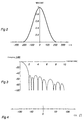
- Figure 2 shows an impulse response, obtained by convolution, for an FIR filter for the second, 2.5 th and third tones, suitable as weighting function for five-cylinder engines.
- Figure 3 shows the transfer function for an FIR filter according to Figure 2.
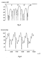
- Figure 6 shows the torque signal from a five-cylinder engine with four misfirings during 10 cycles, filtered by means of an FIR filter according to Figure 2.
- Figure 7 shows the torque signal from the same situation as in Figure 6, filtered by means of a simplified FIR filter according to Figure 4.
- Figure 10 shows the transfer function for a simplified FIR filter according to Figure 9.
- the FIR filtering may be carried out in conventional manner.
- the torque signal is sampled speed-synchronously in an angular interval around each firing pulse and the mean value thereof is formed using a weighting function which for a five-cylinder engine corresponds to the impulse response of a filter for the second, 2.5 th and third tones and their harmonics.
- a filter function is obtained by convoluting a second, 2.5 th and third tone filter with one another.
- the convolution integral is approximated by steps corresponding to the sampling step and requires as many multiplications and additions as the number of samples which corresponds to the length of the impulse response.
- the second-tone filter is rectangular with the value 1 for an interval of 180° and the value 0 for the remaining part of a work cycle (two turns, 720°).
- a 144° interval with the value 1 corresponds to the filter of the 2.5 th tone, a 120° interval with the value 1 the third-tone filter, etc.
- the phase position that is, the centring of these intervals around an angle measured from the upper dead centre at the beginning of the power stroke, may be chosen for optimization of the result.
- the weighting function of the filter is shown, which has been achieved with the already-described convoluting operation with the second, 2.5 th and third tones in Figure 2, where the weighting function is shown in arbitrary units as a function of the angle relative to the upper dead centre at the beginning of the power stroke.
- Figure 3 shows the transfer function, that is, the damping in decibels as a function of the frequency in speed units, for this filter.
- misfiring detector takes place in a microcomputer system operating in real time.
- the filtering is carried out digitally in the software.
- the misfiring detector may be combined with measurement of the voltage across the spark plug and its duration to be able to determine whether the misfiring is caused by a fault in the ignition system.
Landscapes
- Engineering & Computer Science (AREA)
- Chemical & Material Sciences (AREA)
- Combustion & Propulsion (AREA)
- Mechanical Engineering (AREA)
- General Engineering & Computer Science (AREA)
- Physics & Mathematics (AREA)
- General Physics & Mathematics (AREA)
- Combined Controls Of Internal Combustion Engines (AREA)
- Force Measurement Appropriate To Specific Purposes (AREA)
- Ignition Installations For Internal Combustion Engines (AREA)
Claims (29)
- Verfahren zur Erfassung von Fehlzündungen in einem Verbrennungsmotor (1), bei dem das Drehmoment des Verbrennungsmotors mit Hilfe eines, auf der Kurbelwelle (3) des Verbrennungsmotors angebrachten Drehmoment-Sensors (2) erfaßt wird und bei dem ein Drehmomentsignal Geschwindigkeits-synchron mit Hilfe eines Sensors (4) gewonnen wird, wobei das Verfahren dadurch gekennzeichnet ist, daß eine digitale Filterung des Drehmomentsignals mit einem Digitalfilter (5) mit einem begrenztem Ansprechen auf einen Impuls durchgeführt wird, welches eine Auswahl von ganzzahligen oder halb-ganzzahligen Vielfachen der Geschwindigkeit des Verbrennungsmotors blockiert oder dämpft, wobei die Auswahl von Geschwindigkeits-Vielfachen im wesentlichen von der Zylinderzahl des Verbrennungsmotors abhängig ist.
- Verfahren nach Anspruch 1, dadurch gekennzeichnet, daß Frequenzen, die gleich der zweifachen Geschwindigkeit des Verbrennungsmotors sind und deren Vielfache, durch das Digitalfilter blockiert werden.
- Verfahren nach Anspruch 1, dadurch gekennzeichnet, daß mindestens Frequenzen, die gleich der 2-, 2,5- und 3-fachen Geschwindigkeit des Verbrennungsmotors sind, durch das Digitalfilter blockiert werden.
- Verfahren nach Anspruch 1, dadurch gekennzeichnet, daß mindestens Frequenzen, die gleich der 3- und 4,5-fachen Geschwindigkeit des Verbrennungsmotors sind, durch das Digitalfilter blockiert werden.
- Verfahren nach Anspruch 1, dadurch gekennzeichnet, daß mindestens Frequenzen, die gleich der 4-, 5- und 6-fachen Geschwindigkeit des Verbrennungsmotors sind, durch das Digitalfilter blockiert werden.
- Verfahren nach einem der vorstehenden Ansprüche, dadurch gekennzeichnet, daß die digitale Filterung einmal während des Arbeitszyklus von jedem Zylinder durchgeführt wird.
- Verfahren nach einem der Ansprüche 1, 2 oder 6, dadurch gekennzeichnet, daß das Digitalfilter als ein Kammfilter angeordnet ist.
- Verfahren nach Anspruch 1, oder nach den Ansprüchen 3 bis 6, dadurch gekennzeichnet, daß das Digitalfilter durch Faltung von zwei oder mehr Kammfiltern erhalten wird.
- Verfahren nach einem der Ansprüche 1 bis 6, dadurch gekennzeichnet, daß die Filterung durch Addition einer Auswahl von Stichprobenpunkten des Drehmomentsignals erreicht wird, wobei diese Stichprobenpunkte derart auf Kurbelwellen-Winkel verteilt sind, daß das Filter dazu angepasst, eines oder mehrere der Geschwindigkeits-Vielfachen zu blockieren oder zu dämpfen.
- Verfahren nach einem der vorstehenden Ansprüche, dadurch gekennzeichnet, daß Fehlzündung angezeigt wird, wenn eine Abweichung eines angezeigten, mittleren wirksamen Drehmoments, erhalten durch eine Filterung, für einen Zylinder von einem gewichteten Mittelwert des angezeigten, mittleren wirksamen Drehmoments von benachbarten Zündungen einen Schwellenwert überschreitet, der von dem angezeigten, mittleren wirksamen Drehmoment abhängen kann.
- Verfahren nach Anspruch 1 und 10, dadurch gekennzeichnet, daß der Schwellenwert teilweise durch eine in fortgesetzter Weise gebildete Standardabweichung von mehreren vorhergehenden Zündungen bestimmt ist.
- Verfahren nach einem der vorstehenden Ansprüche, dadurch gekennzeichnet, daß ein Mittelwert des angezeigten, mittleren wirksamen Drehmoments während mehrerer Zündungen für jeden Zylinder gebildet wird und zur Erfassung von fortgesetzter Fehlzündung und/oder einem Ungleichgewicht zwischen den Zylindern verwendet wird.
- Verfahren nach einem der vorstehenden Ansprüche, dadurch gekennzeichnet, daß der Drehmoment-Sensor zwischen der Kurbelwelle und einem Schwungrad angeordnet ist.
- Verfahren nach einem der vorstehenden Ansprüche, dadurch gekennzeichnet, daß zusätzlich eine Spannung über die Zündkerze und die Dauer davon erfaßt wird.
- Verbrennungsmotor (1) - Fehlzündungs - erfassende Vorrichtung, welche umfaßt, einen auf der Kurbelwelle (3) des Verbrennungsmotors angebrachten Drehmoment-Sensor (2) zur Erfassung des Drehmoments des Verbrennungsmotors, wobei ein Drehmomentsignal von dem Drehmoment-Sensor Geschwindigkeits-synchron mit der Hilfe eines Sensors (4) gewonnen wird, dadurch gekennzeichnet, daß ein Digitalfilter (5) eine Digitalfilterung des Drehmomentsignals durchführt, wobei das Filter eine Auswahl von ganzzahligen oder halb-ganzzahligen Vielfachen der Geschwindigkeit des Verbrennungsmotors blockiert oder dämpft, wobei die Auswahl von Geschwindigkeitsvielfachen im wesentlichen von der Zylinderzahl des Verbrennungsmotors abhängig ist.
- Vorrichtung nach Anspruch 15, dadurch gekennzeichnet, daß das Digitalfilter die zweifache Geschwindigkeit des Verbrennungsmotors und deren Vielfache blockiert.
- Vorrichtung nach Anspruch 15, dadurch gekennzeichnet, daß das Digitalfilter mindestens Frequenzen, die gleich der 2-, 2,5- und 3-fachen Geschwindigkeit des Verbrennungsmotors sind, blockiert.
- Vorrichtung nach Anspruch 15, dadurch gekennzeichnet, daß das Digitalfilter mindestens Frequenzen, die gleich der 3- und 4,5-fachen Geschwindigkeit des Verbrennungsmotors sind, blockiert.
- Vorrichtung nach Anspruch 15, dadurch gekennzeichnet, daß das Digitalfilter mindestens Frequenzen, die gleich der 4-, 5- und 6-fachen Geschwindigkeit des Verbrennungsmotors sind, blockiert.
- Vorrichtung nach einem der Ansprüche 15 bis 19, dadurch gekennzeichnet, daß die Vorrichtung die digitale Filterung einmal während des Arbeitszyklus von jedem Zylinder durchführt.
- Vorrichtung nach einem der Ansprüche 15, 16 oder 20, dadurch gekennzeichnet, daß das Digitalfilter ein Kammfilter ist.
- Vorrichtung nach Anspruch 15, oder nach den Ansprüchen 17 bis 20, dadurch gekennzeichnet, daß das Digitalfilter durch Faltung von zwei oder mehr Kammfiltern erhalten wird.
- Vorrichtung nach einem der Ansprüche 15 bis 20, dadurch gekennzeichnet, daß die Vorrichtung die Digitalfilterung durch Addition von einer Auswahl von Stichprobenpunkten des Drehmomentsignals durchführt, wobei diese Stichprobenpunkte derart auf Kurbelwellen-Winkeln verteilt sind, daß das Filter bei einem oder mehreren Geschwindigkeitsvielfachen stark blockiert oder dämpft.
- Vorrichtung nach einem der Ansprüche 15 bis 23, dadurch gekennzeichnet, daß sie Fehlzündung anzeigt, wenn eine Abweichung eines angezeigten, mittleren wirksamen Drehmoments, erhalten durch eine Filterung, für einen Zylinder von einem gewichteten Mittelwert des angezeigten, mittleren wirksamen Drehmoments von benachbarten Zündungen einen Schwellenwert überschreitet, der von dem angezeigten, mittleren wirksamen Drehmoment abhängen kann.
- Vorrichtung nach Anspruch 15 bis 24, dadurch gekennzeichnet, daß der Schwellenwert teilweise von einer in fortgesetzter Weise gebildeten Standardabweichung von mehreren vorhergehenden Zündungen abhängig ist.
- Vorrichtung nach einem der Ansprüche 15 bis 25, dadurch gekennzeichnet, daß die Vorrichtung für jeden Zylinder einen Mittelwert des angezeigten, mittleren wirksamen Drehmoments während mehrerer Zündungen zur Erfassung von fortgesetzter Fehlzündung und/oder einem Ungleichgewicht zwischen den Zylindern bildet.
- Vorrichtung nach einem der Ansprüche 15 bis 26, dadurch gekennzeichnet, daß der Drehmoment-Sensor zwischen der Kurbelwelle und einem Schwungrad angeordnet ist.
- Vorrichtung nach einem der Ansprüche 15 bis 27, dadurch gekennzeichnet, daß der Drehmoment-Sensor ein magnetoelastischer Transducer ist.
- Vorrichtung nach einem der Ansprüche 15 bis 28, dadurch gekennzeichnet, daß die Vorrichtung ebenfalls Mittel zur Erfassung einer Spannung durch die Zündkerze und der Dauer davon umfaßt.
Applications Claiming Priority (3)
| Application Number | Priority Date | Filing Date | Title |
|---|---|---|---|
| SE9602437 | 1996-06-20 | ||
| SE9602437A SE506547C2 (sv) | 1996-06-20 | 1996-06-20 | Förfarande och anordning för att detektera feltändning hos en förbränningsmotor |
| PCT/SE1997/001120 WO1997048894A1 (en) | 1996-06-20 | 1997-06-19 | Method and device for detecting misfiring of internal combustion engines |
Publications (2)
| Publication Number | Publication Date |
|---|---|
| EP0906501A1 EP0906501A1 (de) | 1999-04-07 |
| EP0906501B1 true EP0906501B1 (de) | 2001-11-07 |
Family
ID=20403087
Family Applications (1)
| Application Number | Title | Priority Date | Filing Date |
|---|---|---|---|
| EP97930942A Expired - Lifetime EP0906501B1 (de) | 1996-06-20 | 1997-06-19 | Verfahren und vorrichtung zum erfassen von fehlzündungen in verbrennungsmotoren |
Country Status (8)
| Country | Link |
|---|---|
| US (1) | US6158273A (de) |
| EP (1) | EP0906501B1 (de) |
| JP (1) | JP4097703B2 (de) |
| AU (1) | AU3469897A (de) |
| DE (1) | DE69708089T2 (de) |
| ES (1) | ES2168649T3 (de) |
| SE (1) | SE506547C2 (de) |
| WO (1) | WO1997048894A1 (de) |
Families Citing this family (12)
| Publication number | Priority date | Publication date | Assignee | Title |
|---|---|---|---|---|
| SE511278C2 (sv) * | 1997-08-07 | 1999-09-06 | Abb Ab | Vinkelaccelerationsgivare |
| US6415656B1 (en) * | 2000-05-02 | 2002-07-09 | Ford Global Technologies, Inc. | Onboard diagnostic misfire detection monitor for internal combustion engines |
| DE10122517C1 (de) * | 2001-05-09 | 2002-06-20 | Mtu Friedrichshafen Gmbh | Drehzahl-Filter |
| FR2872905B1 (fr) * | 2004-07-06 | 2006-09-22 | Snr Roulements Sa | Procede de determination d'une condition de roulage par analyse harmonique spatiale de la vitesse |
| MX2007014782A (es) | 2005-05-23 | 2008-02-19 | Novartis Ag | Formas cristalinas y otras formas de las sales de acido lactico de 4-amino-5-fluoro-3-[6-(4-metilpiperazin-1-il)-1h-bencimidazol-2 -il]-1h quinolin-2-ona. |
| US7201044B1 (en) * | 2005-09-27 | 2007-04-10 | Honeywell International, Inc. | Torque sensor integrated with engine components |
| JP4702169B2 (ja) * | 2006-05-09 | 2011-06-15 | トヨタ自動車株式会社 | 内燃機関装置およびこれを搭載する車両並びに内燃機関の失火判定方法 |
| DE102009007365B4 (de) * | 2009-02-04 | 2010-12-02 | Continental Automotive Gmbh | Fehleranalyseverfahren und Fehleranalysevorrichtung für einen Verbrennungsmotor |
| DE102011083857A1 (de) * | 2011-09-30 | 2013-04-04 | Siemens Aktiengesellschaft | Verfahren und Anordnung zur Bestimmung der Rotationsgeschwindigkeit von ferromagnetischen Bauteilen |
| DE102015211593B4 (de) * | 2015-06-23 | 2018-10-04 | Schaeffler Technologies AG & Co. KG | Verfahren und Vorrichtung zur Erkennung von Zündaussetzern einer Brennkraftmaschine |
| JP7363714B2 (ja) * | 2020-08-07 | 2023-10-18 | トヨタ自動車株式会社 | 内燃機関の失火検出装置 |
| CN116867961B (zh) * | 2021-03-10 | 2026-03-27 | 日立安斯泰莫株式会社 | 电子控制装置及燃烧状态检测系统 |
Family Cites Families (11)
| Publication number | Priority date | Publication date | Assignee | Title |
|---|---|---|---|---|
| US5278760A (en) * | 1990-04-20 | 1994-01-11 | Hitachi America, Ltd. | Method and system for detecting the misfire of an internal combustion engine utilizing engine torque nonuniformity |
| JPH0436047A (ja) * | 1990-05-31 | 1992-02-06 | Fuji Heavy Ind Ltd | エンジンの失火診断装置 |
| US5902934A (en) * | 1990-12-10 | 1999-05-11 | Sensortech, L.P. | Phase magnitude signal detector |
| US5269178A (en) * | 1990-12-10 | 1993-12-14 | Sensortech, L.P. | Engine misfire, knock of roughness detection method and apparatus |
| US5869752A (en) * | 1990-12-10 | 1999-02-09 | Sensortech L.L.C. | Engine degradation detector |
| US5495774A (en) * | 1993-06-10 | 1996-03-05 | Sensortech L.P. | Magnetostrictive torque sensor air gap compensator |
| US5675094A (en) * | 1990-12-10 | 1997-10-07 | Sensortech Lp | Load variation detector |
| KR950013542B1 (ko) * | 1991-07-17 | 1995-11-08 | 미쓰비시 덴키 가부시키가이샤 | 내연기관 실화검출장치 |
| FR2681425B1 (fr) * | 1991-09-12 | 1993-11-26 | Renault Regie Nale Usines | Procede et dispositif de mesure du couple d'un moteur thermique a combustion interne. |
| JP3315724B2 (ja) * | 1992-08-07 | 2002-08-19 | トヨタ自動車株式会社 | 失火検出装置 |
| IT1260957B (it) * | 1993-08-04 | 1996-04-29 | Fiat Ricerche | Procedimento e sistema per la rilevazione di mancate combustioni in motori a combustione interna. |
-
1996
- 1996-06-20 SE SE9602437A patent/SE506547C2/sv not_active IP Right Cessation
-
1997
- 1997-06-19 EP EP97930942A patent/EP0906501B1/de not_active Expired - Lifetime
- 1997-06-19 ES ES97930942T patent/ES2168649T3/es not_active Expired - Lifetime
- 1997-06-19 WO PCT/SE1997/001120 patent/WO1997048894A1/en not_active Ceased
- 1997-06-19 JP JP50283398A patent/JP4097703B2/ja not_active Expired - Fee Related
- 1997-06-19 US US09/202,451 patent/US6158273A/en not_active Expired - Fee Related
- 1997-06-19 DE DE69708089T patent/DE69708089T2/de not_active Expired - Fee Related
- 1997-06-19 AU AU34698/97A patent/AU3469897A/en not_active Abandoned
Also Published As
| Publication number | Publication date |
|---|---|
| SE9602437D0 (sv) | 1996-06-20 |
| JP4097703B2 (ja) | 2008-06-11 |
| WO1997048894A1 (en) | 1997-12-24 |
| SE506547C2 (sv) | 1998-01-12 |
| EP0906501A1 (de) | 1999-04-07 |
| US6158273A (en) | 2000-12-12 |
| AU3469897A (en) | 1998-01-07 |
| ES2168649T3 (es) | 2002-06-16 |
| DE69708089T2 (de) | 2002-08-29 |
| JP2000513063A (ja) | 2000-10-03 |
| DE69708089D1 (de) | 2001-12-13 |
| SE9602437L (sv) | 1997-12-21 |
Similar Documents
| Publication | Publication Date | Title |
|---|---|---|
| Hickling et al. | Cavity resonances in engine combustion chambers and some applications | |
| US5392642A (en) | System for detection of low power in at least one cylinder of a multi-cylinder engine | |
| US4424709A (en) | Frequency domain engine defect signal analysis | |
| US5200899A (en) | Method and system for detecting the misfire of an internal combustion engine utilizing angular velocity fluctuations | |
| US5278760A (en) | Method and system for detecting the misfire of an internal combustion engine utilizing engine torque nonuniformity | |
| EP0906501B1 (de) | Verfahren und vorrichtung zum erfassen von fehlzündungen in verbrennungsmotoren | |
| US8078389B2 (en) | Method and apparatus for determining a normal combustion characteristic for an internal combustion engine from an accelerometer signal | |
| US5633456A (en) | Engine misfire detection with digital filtering | |
| JP3526870B2 (ja) | 往復エンジンにおける不点火状態を判定するためのパターン認識方法およびシステム | |
| KR970003681B1 (ko) | 내연기관의 엔진 성능 검사 장치용 토오크 제어 시스템 | |
| EP0720735B1 (de) | System zur erfassung von fehlzündungen und verfahren mit verbesserter signaltreue | |
| JP3463476B2 (ja) | 多気筒内燃機関の失火検出装置 | |
| US5390537A (en) | Combustion state-detecting system for internal combustion engines | |
| US5493901A (en) | Combustion state-detecting system for internal combustion engines | |
| KR100507205B1 (ko) | 노킹 센서 장착 위치 설정 방법 | |
| Shiao et al. | Misfire detection and cylinder pressure reconstruction for SI engines | |
| KR101307017B1 (ko) | 내연 피스톤 엔진 시스템내에서 실린더출력의 불균일공유상태를 확인하기 위한 장치 | |
| EP0423130A1 (de) | Verfahren und vorrichtung zur messung von verbrennungsvorgängen in einer brennkraftmaschine. | |
| JP2009541629A (ja) | ミスファイアを検出する方法および相応する装置 | |
| WO1984000417A1 (en) | Frequency domain engine defect signal analysis | |
| US5415035A (en) | Combustion state-detecting system for internal combustion engines | |
| Pischinger et al. | A new measuring method for the direct determination of Diesel engine combustion noise | |
| KR20210005823A (ko) | 비틀림진동 신호를 이용한 왕복동 내연기관의 착화실패 실린더 검출 방법 및 그 장치 | |
| Rath et al. | Analysis of autoregressive coefficients of knock sensor signals for misfire detection in internal combustion engines | |
| JP4316914B2 (ja) | 失火検出装置 |
Legal Events
| Date | Code | Title | Description |
|---|---|---|---|
| PUAI | Public reference made under article 153(3) epc to a published international application that has entered the european phase |
Free format text: ORIGINAL CODE: 0009012 |
|
| 17P | Request for examination filed |
Effective date: 19981214 |
|
| AK | Designated contracting states |
Kind code of ref document: A1 Designated state(s): DE ES FR GB IT NL |
|
| RAP1 | Party data changed (applicant data changed or rights of an application transferred) |
Owner name: ABB AB |
|
| GRAG | Despatch of communication of intention to grant |
Free format text: ORIGINAL CODE: EPIDOS AGRA |
|
| GRAG | Despatch of communication of intention to grant |
Free format text: ORIGINAL CODE: EPIDOS AGRA |
|
| GRAH | Despatch of communication of intention to grant a patent |
Free format text: ORIGINAL CODE: EPIDOS IGRA |
|
| 17Q | First examination report despatched |
Effective date: 20010411 |
|
| GRAH | Despatch of communication of intention to grant a patent |
Free format text: ORIGINAL CODE: EPIDOS IGRA |
|
| GRAA | (expected) grant |
Free format text: ORIGINAL CODE: 0009210 |
|
| AK | Designated contracting states |
Kind code of ref document: B1 Designated state(s): DE ES FR GB IT NL |
|
| REF | Corresponds to: |
Ref document number: 69708089 Country of ref document: DE Date of ref document: 20011213 |
|
| REG | Reference to a national code |
Ref country code: GB Ref legal event code: IF02 |
|
| REG | Reference to a national code |
Ref country code: ES Ref legal event code: FG2A Ref document number: 2168649 Country of ref document: ES Kind code of ref document: T3 |
|
| PLBE | No opposition filed within time limit |
Free format text: ORIGINAL CODE: 0009261 |
|
| STAA | Information on the status of an ep patent application or granted ep patent |
Free format text: STATUS: NO OPPOSITION FILED WITHIN TIME LIMIT |
|
| 26N | No opposition filed | ||
| PGFP | Annual fee paid to national office [announced via postgrant information from national office to epo] |
Ref country code: NL Payment date: 20090603 Year of fee payment: 13 |
|
| PGFP | Annual fee paid to national office [announced via postgrant information from national office to epo] |
Ref country code: IT Payment date: 20090618 Year of fee payment: 13 |
|
| PGFP | Annual fee paid to national office [announced via postgrant information from national office to epo] |
Ref country code: ES Payment date: 20090709 Year of fee payment: 13 |
|
| PGFP | Annual fee paid to national office [announced via postgrant information from national office to epo] |
Ref country code: GB Payment date: 20090617 Year of fee payment: 13 Ref country code: DE Payment date: 20090615 Year of fee payment: 13 |
|
| REG | Reference to a national code |
Ref country code: NL Ref legal event code: V1 Effective date: 20110101 |
|
| GBPC | Gb: european patent ceased through non-payment of renewal fee |
Effective date: 20100619 |
|
| REG | Reference to a national code |
Ref country code: FR Ref legal event code: ST Effective date: 20110228 |
|
| PG25 | Lapsed in a contracting state [announced via postgrant information from national office to epo] |
Ref country code: IT Free format text: LAPSE BECAUSE OF NON-PAYMENT OF DUE FEES Effective date: 20100619 |
|
| PG25 | Lapsed in a contracting state [announced via postgrant information from national office to epo] |
Ref country code: DE Free format text: LAPSE BECAUSE OF NON-PAYMENT OF DUE FEES Effective date: 20110101 |
|
| PG25 | Lapsed in a contracting state [announced via postgrant information from national office to epo] |
Ref country code: FR Free format text: LAPSE BECAUSE OF NON-PAYMENT OF DUE FEES Effective date: 20100630 Ref country code: NL Free format text: LAPSE BECAUSE OF NON-PAYMENT OF DUE FEES Effective date: 20110101 |
|
| REG | Reference to a national code |
Ref country code: ES Ref legal event code: FD2A Effective date: 20110715 |
|
| PG25 | Lapsed in a contracting state [announced via postgrant information from national office to epo] |
Ref country code: ES Free format text: LAPSE BECAUSE OF NON-PAYMENT OF DUE FEES Effective date: 20110705 Ref country code: GB Free format text: LAPSE BECAUSE OF NON-PAYMENT OF DUE FEES Effective date: 20100619 |
|
| PG25 | Lapsed in a contracting state [announced via postgrant information from national office to epo] |
Ref country code: ES Free format text: LAPSE BECAUSE OF NON-PAYMENT OF DUE FEES Effective date: 20100620 |
|
| PGFP | Annual fee paid to national office [announced via postgrant information from national office to epo] |
Ref country code: FR Payment date: 20090611 Year of fee payment: 13 |