EP0720735B1 - System zur erfassung von fehlzündungen und verfahren mit verbesserter signaltreue - Google Patents
System zur erfassung von fehlzündungen und verfahren mit verbesserter signaltreue Download PDFInfo
- Publication number
- EP0720735B1 EP0720735B1 EP95925497A EP95925497A EP0720735B1 EP 0720735 B1 EP0720735 B1 EP 0720735B1 EP 95925497 A EP95925497 A EP 95925497A EP 95925497 A EP95925497 A EP 95925497A EP 0720735 B1 EP0720735 B1 EP 0720735B1
- Authority
- EP
- European Patent Office
- Prior art keywords
- reciprocating engine
- filter
- acceleration signal
- determining
- operating condition
- Prior art date
- Legal status (The legal status is an assumption and is not a legal conclusion. Google has not performed a legal analysis and makes no representation as to the accuracy of the status listed.)
- Expired - Lifetime
Links
- 238000001514 detection method Methods 0.000 title claims description 33
- 238000000034 method Methods 0.000 title claims description 19
- 230000001133 acceleration Effects 0.000 claims description 122
- 230000005540 biological transmission Effects 0.000 claims description 37
- 230000001419 dependent effect Effects 0.000 claims description 31
- 238000005259 measurement Methods 0.000 claims description 20
- 230000008878 coupling Effects 0.000 claims description 12
- 238000010168 coupling process Methods 0.000 claims description 12
- 238000005859 coupling reaction Methods 0.000 claims description 12
- 230000007423 decrease Effects 0.000 claims description 6
- 230000006399 behavior Effects 0.000 description 33
- 230000000694 effects Effects 0.000 description 14
- 238000010304 firing Methods 0.000 description 11
- 238000002485 combustion reaction Methods 0.000 description 10
- 230000008859 change Effects 0.000 description 6
- 238000013459 approach Methods 0.000 description 5
- 230000003595 spectral effect Effects 0.000 description 5
- 238000013507 mapping Methods 0.000 description 4
- 230000001627 detrimental effect Effects 0.000 description 3
- 238000010586 diagram Methods 0.000 description 3
- 230000009286 beneficial effect Effects 0.000 description 2
- 230000008901 benefit Effects 0.000 description 2
- 230000007935 neutral effect Effects 0.000 description 2
- 230000010355 oscillation Effects 0.000 description 2
- 230000008569 process Effects 0.000 description 2
- 230000000638 stimulation Effects 0.000 description 2
- 238000012935 Averaging Methods 0.000 description 1
- 230000003542 behavioural effect Effects 0.000 description 1
- 230000003750 conditioning effect Effects 0.000 description 1
- 238000006073 displacement reaction Methods 0.000 description 1
- 238000001914 filtration Methods 0.000 description 1
- 230000006872 improvement Effects 0.000 description 1
- 238000004519 manufacturing process Methods 0.000 description 1
- 230000007246 mechanism Effects 0.000 description 1
- 238000012544 monitoring process Methods 0.000 description 1
- 230000003534 oscillatory effect Effects 0.000 description 1
- 230000001151 other effect Effects 0.000 description 1
- 238000012545 processing Methods 0.000 description 1
- 230000004044 response Effects 0.000 description 1
- 238000010183 spectrum analysis Methods 0.000 description 1
- 230000001052 transient effect Effects 0.000 description 1
Images


Classifications
-
- G—PHYSICS
- G01—MEASURING; TESTING
- G01M—TESTING STATIC OR DYNAMIC BALANCE OF MACHINES OR STRUCTURES; TESTING OF STRUCTURES OR APPARATUS, NOT OTHERWISE PROVIDED FOR
- G01M15/00—Testing of engines
- G01M15/04—Testing internal-combustion engines
- G01M15/11—Testing internal-combustion engines by detecting misfire
Definitions
- This invention is generally directed to the field of engine controls, and specifically to a signal processing system and method for detecting a misfiring condition in a reciprocating engine.
- crankshaft engine angular velocity and sometimes crankshaft or other forms of, engine acceleration, both dependent largely on engine torque produced during a combustion process to determine misfiring of a particular engine cylinder.
- misfires are predicted by various signature analysis, and/or spectral analysis, methods.
- the engine angular velocity and acceleration behavior is also affected by powertrain related behaviors other than firing torque. These other behaviors can significantly reduce fidelity or signal-noise ratio of the primarily firing torque related velocity or acceleration signal under analysis. Furthermore, under some engine operating conditions, the noise exceeds the primarily engine torque related velocity or acceleration signal under analysis. Moreover, the noise related behavior is not limited to engine operation only causes, but include behaviors related to the complete driveline. Some noise related behaviors that are detrimental include driveline resonance effects. or vibrations, excited at least partially by cylinder misfiring, torque converter lockup, low speed lugging behavior characteristic of a manual transmission, a change in transmission gears and rough road conditions. Each of these, and other sources of stimulus, excite the driveline to perturbate, or transiently oscillate, at its resonant frequency.
- FIG. 1 shows a 1st portion 101 of a waveform indicative of acceleration of an engine's crankshaft due to a properly firing cylinder, firing in a sequence of several cylinders, and a 2nd portion 103 waveform indicative of acceleration of an engine's crankshaft due to a misfiring cylinder later in the sequence of firing cylinders.
- the engine's crankshaft grossly decels because proper firing did not occur and therefore the cylinder did not add the expected torque to the crankshaft as it did at reference number 101.
- his is a theoretical representation of the acceleration effect. If the actual behavior produced by the engine crankshaft is that shown in FIG. 1 then a comparison process can monitor the behavior at a predetermined threshold 105 and indicate a misfiring condition if the waveform goes below the threshold.
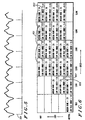
- FIG. 2 illustrates a behavior of an actual acceleration signal 201 derived from a running engine over about 150 cylinder combustion cycles.
- This acceleration signal 201 includes a repetitively induced misfire by periodically removing a spark signal from one cylinder. So, in a real-world application on the signal derived from a running engine is effected by other than combustion related torque as earlier mentioned.
- the tick lines 203 on the horizontal axis demarcate the deliberately induced occurrences of misfire.
- the waveform 201 is derived using an acceleration sensing device coupled to the engine's crankshaft.
- the waveform shown in FIG.2 has poor fidelity and therefore the acceleration signal related to the misfire cannot be clearly seen and thereby detected as discussed in FIG.1. Additionally, the above-mentioned driveline resonance effects are also represented in the subject waveform in FIG.2 and significantly reduce the fidelity of the signal making detection by a simple threshold detection scheme hopeless.
- One prior art scheme averages the engine acceleration waveform to improve the fidelity by eliminating cylinder-to-cylinder variability at least partially influenced by engine related vibrations.
- these fixed averaging schemes perform inadequately over all engine operating conditions - particularly at high engine speeds and light engine loads.
- US5044194 discloses a misfire detection in an internal combustion engine method and apparatus during actual driving conditions
- US5387253 discloses a system and corresponding method for detection the presence of a misfire condition by interpreting spectral activity of a running engine.
- Another prior art scheme applies a chassis mounted accelerometer to predict driveline vibrations characteristic of a subset of the above-mentioned behaviors. Accordingly, if one of these behaviors is sensed the misfire detection scheme is disabled. This prevents false detection of what appears to emulate a misfire but is in fact a driveline perturbation caused by, for instance, a rough road condition. Of course this scheme will also fail to detect misfires occurring during this disabling process. Abdication to predict meaningful misfires aside, this scheme is complex, unreliable, difficult to manufacture, and very costly because it adds another sensor and its associated supporting wiring, electrical interface, and signal conditioning circuitry.
- Another scheme employs a fixed rank median filter to determine gross, or average, acceleration of an engine which is then used to filter-out certain transient effects.
- This scheme lacks the ability to adapt to a wide variety of driveline vibrations caused by various sources of stimulation, not insignificantly misfire induced driveline vibrations, as described above.
- this scheme includes recognition of poor acceleration signal fidelity and disables the misfire detection mechanism when the fidelity is poor. Accordingly, the known prior art only detects a subset of misfiring conditions. This is unacceptable with the strict legislation proposed.
- an acceleration based misfire detection system as claimed in claim 1, and an acceleration based misfire detection method as claimed in claim 22.
- An acceleration based misfire detection system with improved signal fidelity comprises a measurement device for determining an operating condition of the powertrain.
- the operating condition can include engine speed, engine load, as well as other conditions.
- a misfire detector provides a misfire indication dependent on an improved fidelity acceleration signal.
- the improved fidelity acceleration signal is provided by either a median filter operating on an acceleration signal where the median filter's rank is programmable dependent on the determined operating condition of the powertrain, a highpass filter operating on an acceleration signal where the highpass filter's order is programmable dependent on the determined operating condition of the powertrain, or from an acceleration determination device acting on velocity information provided by a lowpass filter operating on a velocity signal where the lowpass filter's order is programmable dependent on the determined operating condition of the powertrain, or a combination of the above.
- a problem with prior art systems is poor signal fidelity.
- the invention described in the preferred embodiment significantly improves signal fidelity.
- the earlier-described engine and driveline vibrations will be filtered out under a wide variety of engine operating conditions thereby significantly improving the acceleration signal fidelity and making reliable and accurate misfire detection possible over those wide range of engine operating conditions.
- FIG. 1 and FIG. 2 are charts showing engine acceleration waveform illustrating respectively theoretical and actual behavioral effects of cylinder firing and misfiring as detailed in the Background section.
- acceleration behavior can be used to analyze misfire behavior.
- behaviors associated with mechanical structural relationships in the engine and associated driveline can add noise which significantly reduces fidelity or signal-noise ratio of the, primarily engine torque related, acceleration signal to be analyzed.
- the noise exceeds the primarily engine torque related acceleration signal under analysis.
- Some noise related behaviors that are detrimental include, engine related effects such as crankshaft torsional vibrations, inertial torque due to reciprocating masses, and other mechanically induced vibrations on the engine's crankshaft add noise to the acceleration measurement and thereby reduce the fidelity of the signal/waveform measured. Additionally, driveline resonance effects, or vibrations, excited at least partially by cylinder misfiring, torque converter lockup, low speed lugging behavior characteristic of a manual transmission, a change in transmission gears and rough road conditions. Each of these, and other sources of stimulus, excite the driveline to perturbate, or transiently oscillate, at its resonant frequency.
- the resonant frequency of the driveline is at least partially dependent on a compliancy of a coupling between the engine and a transmission. This compliancy often largely determines a magnitude and frequency of the driveline vibration behavior. Typically, the less compliant the coupling the greater the magnitude and the more proximate the frequency of oscillation is to the spectral behavior directly caused by misfire on an acceleration measurement. Because of the varied coupling compliancy between the engine and the transmission, and the various sources of driveline stimulation, the magnitude, duration, and frequency of driveline vibrations are variable over various engine operating conditions not least of which include engine speed, engine load, and transmission gear selection.
- FIG. 3 is a chart illustrating various spectral behavior characteristic of engine acceleration due to normal combustion torque, torque due to reciprocating masses, misfiring, torsional vibrations, high-order sub-partials, and driveline vibrations for a 6 cylinder 4-stroke reciprocating engine in terms of engine cycles/revolution.
- Normal combustion firing torque, and torque due to reciprocating masses 301 manifests itself at 3, 6, and 9 cycles/revolution.
- a torsional vibration 303 characteristic of the natural frequency of oscillation of the crankshaft occurs with a substantial magnitude above 3 cycles/revolution.
- the crankshaft torsional vibration moves in order, here measured in cycles/revolution, with engine speed.
- High-order sub-partial energy 305 occurring at 1 cycle/revolution to 3 cycles/revolution is indicative of vibrations due to encoder (the encoder that is used to measure crankshaft angular velocity) profile errors, and piston imbalance.
- Misfire induced energy 307 is indicative of a coil-pack failure at 1 cycle/revolution (since 3 of 6 cylinders normally fires/revolution), or a hard failure of one cylinder at 1/2 cycle/revolution (since each cylinder normally fires every 2 revolutions).
- Intermittent misfire frequencies 317 are below 1/2 cycle/revolution. Their specific position on the chart will be determined by their periodicity.
- Driveline vibrations 309 at least partially caused by cylinder misfiring, torque converter lockup, low speed lugging behavior characteristic of a manual transmission, a change in transmission gears and rough road conditions, occur at a characteristically low order, are relatively strong in magnitude, shift around in order, and are positioned precariously proximate the energy associated with misfire.
- FIG. 4 a system block diagram illustrates a misfire detection system 400 including system for filtering out the averse effects of, extraneous engine vibrations and driveline vibrations, in accordance with a preferred embodiment of the invention.
- This system 400 is used to detect a misfiring condition using engine acceleration as a metric of combustion performance. Furthermore, it has the capability of significantly improving acceleration signal fidelity through a structure including two programmable filters. Preferably, these are programmable digital filters that are programmed in response to powertrain operating conditions and are configured dynamically as the powertrain operating conditions change.
- a reciprocating engine and driveline 401 represents the aforementioned powertrain.
- the driveline includes an engine, an engine-transmission coupling, a transmission coupled to a driveshaft, coupled to an axle, coupled to vehicular drive wheels.
- the exact configuration of the driveline may be different.
- a crankshaft sensor 403 is coupled to the engine and is used to measure angular displacement and speed of the engine's crankshaft by sensing teeth on a toothed wheel mounted on the crankshaft.
- elements imbedded within an area demarked by reference number 402 are emulated in a digital hardwired circuit on an ASIC (Application Specific Integrated Circuit).
- This digital circuit 402 responsive to the crankshaft speed sensor 403 operates continuously on a discrete stream of data.
- these elements may be emulated in microcoded software executed on a digital signal processor or DSP.
- DSP digital signal processor
- a Motorola DSP56001 device may be used.
- those skilled in the art will recognize other equivalently useful hardwired, software emulated, and DSP approaches to perform the intended function of this area 402 of the system block diagram.
- a signal derived from the crankshaft sensor 403 is used to derive angular velocity of the engine's crankshaft dependent on a known angular spacing of the teeth on the toothed wheel, and a time measured between the teeth.
- a signal 406 provided by block 405 is a discrete time sampled representation of the derived velocity.
- an order programmable lowpass filter is used to attenuate the crankshaft torsional vibrations, inertial torque due to reciprocating masses, and other mechanically induced vibrations on the engine's crankshaft and normal combustion from the misfire energy which occurs at 1.0 cycle/revolution or less introduced in FIG. 3, and to provide a lowpass filtered velocity signal 408.
- the programmable lowpass filter is shown to filter a velocity signal before determination of acceleration, it may also act directly on an acceleration signal.
- the programmable lowpass filter 407 is configured to operate in the cycles/revolution domain because the misfire related energy 307 is stationary in the cycles/revolution domain over various engine speeds, making the control of the lowpass filter order simple.
- the programmable lowpass filter 407 can be configured to operate in another domain - such as the time domain.
- the programmable lowpass filter's 407 order selection is controlled by system block 429, which is described later.
- the programmable lowpass filter's 407 order can be made variable as a function of engine speed and load to improve signal fidelity so that misfire detection capability can be enhanced. Details of how this programmable lowpass filter 407 order is programmed will be detailed below.
- a continuous time sampled acceleration signal 411 is derived from the lowpass filtered velocity signal 408.
- the lowpass filtered acceleration signal 411 is provided to a programmable median filter 413.
- the programmable median filter 413 performs a nonlinear filter function, similar to that of a highpass filter, to remove low frequency driveline vibrations (see FIG. 3 reference number 309).
- the rank of the programmable median filter 413 is chosen to match a period of monotonicity in the acceleration signal.
- the median filter can mask or filter out the driveline oscillatory vibrations corresponding to this period of monotonicity. This in-effect will serve the function of a traditional highpass filter. Although a traditional highpass filter will work it is less desirable because of the complexity required to match the performance of the median filter.
- the programmable median filter 413 provides an improved fidelity median filtered signal 415 to be used to detect misfire. The programmable median filter 413 works as follows.
- the number of data samples "n" of the list is considered the rank of the programmable median filter 413.
- the acceleration data corresponding to the sample having the median magnitude is then subtracted from an acceleration data value at the center of the unsorted continuous list. For example:
- the rank, or length of the list is five.
- the programmable median filter's 413 order selection is controlled by system block 433, which is detailed later.
- the rank of the programmable median filter 413 can be made to be variable dependent on engine load, engine speed, transmission gear to improve misfire detection. Additionally, the rank of the programmable median filter 413 can be made to be variable dependent on engine-transmission coupling, to improve misfire detection capability during torque converter lockup, low speed lugging and rough road conditions. Note that at high engine speeds, it may be beneficial to completely disable the programmable median filter 413.
- An engine speed measurement system 421 derives engine speed. This is preferably accomplished by using the crankshaft sensor 403 described above.
- An engine load measurement system 423 derives engine load either by determining mass air flow of the engine, or alternatively by combining a measurement of manifold absolute pressure and engine speed.
- a transmission gear measurement system 425 derives transmission gear by monitoring a transmission provided signal indicative of transmission gear. Also, a lockup state of the transmission is determined by the engine to transmission coupling compliancy measurement system 427 from a similar signal provided from the transmission. The transmission coupling compliancy measurement system 427 also indicates the type, either manual or automatic, transmission coupled to the engine.
- the above-mentioned block 429 is an engine operating condition-order selection mapping device which stores filter coefficients 431 to be provided to the order programmable lowpass filter 407, as a function of engine speed and engine load provided by the engine speed measurement system 421 and the engine load measurement system 423 respectively. Details of the filter order associated with the coefficients and their dependency on engine speed and load will be detailed later in the discussion of FIG. 6.
- the above-mentioned block 433 is an engine operating condition-rank selection mapping device which stores filter rank 435 to be provided to the programmable median filter 413, as a function of engine speed, engine load, transmission gear, and engine-transmission coupling compliancy provided by the above described systems 421, 423, 425, and 427. Details of the filter rank selected will be detailed later in the discussion of FIG. 6.
- a misfire detection block 417 uses the improved fidelity median filtered signal 415 to determine a misfiring condition, indicated by signal 419, by comparing the improved fidelity median filtered signal 415 with a calibrated threshold.
- a first example of the improved system and method addresses a steady-state engine operating condition represented originally in FIG. 2 which shows an engine acceleration waveform from an actual engine running at 5,000 RPM under a light load.
- FIG. 2 shows an engine acceleration waveform from an actual engine running at 5,000 RPM under a light load.
- vibrations due to encoder profile error, and piston imbalance produce substantial interference at 1.0 cycle/revolution.
- the order programmable lowpass filter 407 shown in FIG. 4 is programmed to respond at 0.01 cycles/revolution. Referring back to FIG. 3 this result can be seen at reference number 313. It can be clearly seen that by reducing the order of the order programmable lowpass filter 407 that the torsional vibration 303, the normal combustion firing torque, and torque due to reciprocating masses 301 occurring at 3, 6, and, 9 cycles/revolution, and the high-order sub-partial energy 305 occurring at 1 cycle/revolution to 3 cycles/revolution are eliminated from the waveform shown in FIG. 2. The beneficial result is shown in the waveform of FIG. 5 in terms of acceleration. Note the clearly distinct occurrences of misfire behavior shown demarcated by the tick marks on the horizontal scale 501 which indicates the position of the periodically induced misfires. Using this improved waveform accurate misfire detection becomes possible.
- the order programmable lowpass filter approach can also address and improve fidelity of the acceleration signal over a wide range of engine operating conditions. Some of these are shown in FIG. 6. Specifically, the chart in FIG. 6 shows various lowpass filter order and also median filter rank calibrations over a range of engine operating conditions in terms of engine speed and engine load. In most cases it is desirable to use a 1st order lowpass filter shown at reference number 311 to avoid losing 2/n misfire detection capability. At high engine speeds, as shown previously in FIG. 5, 2/n misfire detection capability must be sacrificed to maintain intermittent and 1/n capability because of an increased amplitude of high-order sub-partial energy at 1.0 cycle/revolution.
- filter both lowpass and median filter programming
- FIG. 6 It is desirable to vary lowpass filter order and median filter rank as shown below to maintain adequate misfire detection capability over the engine speed/load map.
- reference number 601 shows that as engine speed increases, the median filter rank needs to increase to maintain good signal fidelity.
- Reference number 603 shows that as engine speed increases, the lowpass filter order needs to decrease to maintain good signal fidelity.
- reference number 605 shows that as engine load increases, the median filter rank needs to decrease to maintain good signal fidelity
- reference number 607 shows that as engine load increases, the lowpass filter order needs to increase to maintain good signal fidelity.
- the order and rank selection mapping can be optimized differently for different engine families.
- the programmable median filter may be disabled in some engine families.
- FIG. 7 illustrates the acceleration signal output for a vehicle with an automatic transmission shifting transmission gears from 3rd to 4th.
- a first portion 705 of the waveform 703 represents the reciprocating engine's crankshaft acceleration while the automatic transmission is operating in 3rd gear. Note that the tick marks on the horizontal scale shown at reference number 701 demarcate the position of the periodically induced misfires.
- a second portion 707 of the waveform 703 represents the reciprocating engine's crankshaft acceleration while the automatic transmission is operating in neutral, and a third portion 709 of the waveform 703 represents acceleration behavior of the reciprocating engine's crankshaft while the transmission is operating in 4th gear.
- the acceleration waveform 703 is compared to a threshold, here shown at reference number 711, to detect misfire. Once the acceleration waveform is lower than this threshold 711 a misfire is indicated. Because of the relatively poor fidelity, or signal to noise ratio, of this waveform 703, it can be seen that misfires may be incorrectly indicated when compared to the set threshold 711. In some cases, as illustrated by reference number 713 a magnitude of the noise exceeds a magnitude of the acceleration signal 715. So to reliably detect misfire the fidelity of the acceleration signal needs to be improved prior to the comparison operation.
- FIGS 8 and 9 illustrate results of various median filter rank calibrations that reduce unwanted noise at the lower frequencies characteristic of driveline vibration which vary with engine speed. and other effects described above.
- a portion 801 of the waveform 803, which represents a median filtered version of the waveform 703 over the portion 705 shows the improved fidelity resulting from the application of a rank 61 median filter.
- a portion 901 of the waveform 903, which represents a median filtered version of the waveform 703 over the portion 709 shows the improved fidelity resulting from the application of a rank 29 median filter. Note that the reason for selecting different ranks for the different transmission gears is to optimize the fidelity of the processed acceleration signal under the different engine operating conditions.
Landscapes
- Chemical & Material Sciences (AREA)
- Engineering & Computer Science (AREA)
- Combustion & Propulsion (AREA)
- Physics & Mathematics (AREA)
- General Physics & Mathematics (AREA)
- Combined Controls Of Internal Combustion Engines (AREA)
Claims (31)
- System zur Erfassung von Fehlzündungen für einen Kolbenmotor (401) mit Signaltreue, das umfasst:und das dadurch gekennzeichnet ist, dass die Filtermittel (407, 413) programmierbare Filtermittel sind, so dass eine Filterordnung und ein Rang der gemessenen Geschwindigkeitssignale oder der gemessenen Beschleunigungssignale in Abhängigkeit von der ermittelten Betriebsbedingung des Kolbenmotors verändert werden können, um das gefilterte Geschwindigkeitssignal oder das gefilterte Beschleunigungssignal zur Verfügung zu stellen.a) Mittel zum Messen der Geschwindigkeit oder Beschleunigung (421) zum Bereitstellen jeweils eines Geschwindigkeitssignals oder eines Beschleunigungssignals, welche jeweils das Geschwindigkeitsverhalten oder das Beschleunigungsverhalten des Kolbenmotors anzeigen;b) Mittel zum Ermitteln einer Betriebsbedingung des Kolbenmotors (423, 425, 427);c) Filtermittel (407, 413) zum Bereitstellen eines gefilterten Geschwindigkeitssignals oder eines gefilterten Beschleunigungssignals, die jeweils auf das Geschwindigkeitssignal oder das Beschleunigungssignal reagieren, die jeweils durch die Mittel zum Messen der Geschwindigkeit oder der Beschleunigung zur Verfügung gestellt werden;d) Mittel zum Erfassen von Fehlzündungen (417) zum Ermitteln einer Fehlzündungsbedingung, wobei die Mittel zum Erfassen von Fehlzündungen das gefilterte Geschwindigkeitssignal oder das gefilterte Beschleunigungssignal verwenden, um eine Fehlzündungsbedingung durch Vergleichen des gefilterten Geschwindigkeitssignals oder des gefilterten Beschleunigungssignals mit einem kalibrierten Schwellenwert zu ermitteln;
- System gemäß Anspruch 1, bei dem die Mittel zum Ermitteln einer Betriebsbedingung eines Kolbenmotors (423, 425, 427) eine Last des Kolbenmotors (401) ermitteln und bei dem die Filtermittel (407, 413) einen Tiefpassfilter mit programmierbarer Ordnung umfassen, dessen Ordnung in Abhängigkeit von der ermittelten Last des Kolbenmotors programmiert wird.
- System gemäß Anspruch 1, bei dem die Mittel zum Ermitteln einer Betriebsbedingung des Kolbenmotors (423, 425, 427) eine Geschwindigkeit des Kolbenmotors (401) ermitteln, wobei die Filtermittel (407, 413) einen Hochpassfilter mit programmierbarer Ordnung umfassen, dessen Ordnung in Abhängigkeit der ermittelten Geschwindigkeit des Kolbenmotors programmiert wird, und bei dem der Hochpassfilter ein gefiltertes Beschleunigungssignal zur Verfügung stellt, das auf das Beschleunigungssignal reagiert, welches durch die Mittel zum Messen der Beschleunigung bereitgestellt wird.
- System gemäß Anspruch 1, bei dem die Filtermittel (407, 413) einen programmierbaren Medianfilter umfassen, der einen in Abhängigkeit der ermittelten Betriebsbedingung des Kolbenmotors (423, 425, 427) programmierbaren Rang hat und bei dem der programmierbare Medianfilter ein gefiltertes Beschleunigungssignal zur Verfügung stellt, welches auf das Beschleunigungssignal reagiert, das durch die Mittel zum Messen der Beschleunigung zur Verfügung gestellt wird.
- System gemäß Anspruch 4, bei dem die Mittel zum Ermitteln einer Betriebsbedingung des Kolbenmotors (423, 425, 427) eine Last des Kolbenmotors (401) ermitteln und bei dem der Rang des Medianfilters von der ermittelten Last abhängt.
- System gemäß Anspruch 5, bei dem der Rang des Medianfilters abnimmt, wenn die ermittelte Last ansteigt.
- System gemäß Anspruch 4, bei dem die Mittel zum Ermitteln einer Betriebsbedingung des Kolbenmotors (423, 425, 427) eine Gangauswahl des Getriebes ermitteln, welches mit dem Kolbenmotor (401) gekoppelt ist, und bei dem der Rang des programmierbaren Medianfilters von der ermittelten Auswahl des Getriebeganges abhängt.
- System gemäß Anspruch 5, bei dem der Rang des Medianfilters ansteigt, wie die ermittelte Auswahl des Getriebegangs einem höheren Übersetzungsverhältnis entspricht.
- System gemäß Anspruch 4, bei dem die Mittel zum Ermitteln einer Betriebsbedingung des Kolbenmotors (423, 425, 427) eine Nachgiebigkeit der Kopplung zwischen dem Kolbenmotor (401) und einem Getriebe ermitteln und bei dem der Rang des Medianfilters von der ermittelten Nachgiebigkeit abhängt.
- System gemäß Anspruch 7, bei dem der Rang des Medianfilters ansteigt, wie die ermittelte Nachgiebigkeit der Kopplung zwischen dem Kolbenmotor (401) und dem Getriebe abnimmt.
- System gemäß Anspruch 4, bei dem die Mittel zum Ermitteln einer Betriebsbedingung des Kolbenmotors (423, 425, 427) eine Transmissionsresonanzfrequenz ermitteln und bei dem der Rang des Median-Filters von der ermittelten Transmissionsresonanzfrequenz abhängt.
- System gemäß Anspruch 9, bei dem der Rang des Medianfilters abnimmt, wie die ermittelte Antriebsanlagenresonanzfrequenz ansteigt.
- System gemäß Anspruch 4, bei dem die Mittel zum Ermitteln einer Betriebsbedingung des Kolbenmotors (423, 425, 427) eine Geschwindigkeit des Kolbenmotors ermitteln.
- System gemäß Anspruch 11, bei dem der Rang des Medianfilters ansteigt, wie die ermittelte Geschwindigkeit ansteigt.
- System gemäß Anspruch 4, bei dem der Medianfilter umfasst:Mittel zum Extrahieren eines Medianwertes innerhalb des Rangs des Beschleunigungssignals;
undMittel zum Subtrahieren des Medianwertes innerhalb des Rangs von dem Beschleunigungssignal, um das gefilterte Beschleunigungssignal zu Verfügung zu stellen. - System gemäß Anspruch 13, bei dem die Mittel zum Ermitteln einer Betriebsbedingung des Kolbenmotors (423, 425, 427) eine Last des Kolbenmotors (401) ermitteln und bei dem der Rang des Medianfilters in Abhängigkeit von der ermittelten Last programmiert wird.
- System gemäß Anspruch 14, bei dem der Rang des Medianfilters abnimmt, wie die ermittelte Last ansteigt.
- System gemäß Anspruch 1, bei dem die Mittel zum Ermitteln einer Betriebsbedingung des Kolbenmotors (423, 425, 427) eine Geschwindigkeit des Kolbenmotors (401) ermitteln und ein Motorsignal bereitstellen, das die ermittelte Geschwindigkeit anzeigt, und bei dem die Filtermittel umfassen:einen Tiefpassfilter mit programmierbarer Ordnung zum Empfangen des Beschleunigungssignals und zum Bereitstellen eines tiefpassgefilterten Beschleunigungssignals, wobei eine Ordnung des Tiefpassfilters in Abhängigkeit von der ermittelten Geschwindigkeit des Kolbenmotors programmiert wird;einen Hochpassfilter mit programmierbarer Ordnung zum Empfangen des tiefpassgefilterten Beschleunigungssignals und zum Bereitstellen eines hochpass/tiefpassgefilterten Beschleunigungssignals, wobei eine Ordnung des Hochpassfilters von der ermittelten Geschwindigkeit des Kolbenmotors abhängt undbei dem das Mittel zum Erfassen von Fehlzündungen (417) das Anzeigen einer Fehlzündung in Abhängigkeit von dem hochpass/tiefpassgefilterten Beschleunigungssignal zur Verfügung stellt.
- System gemäß Anspruch 1, bei dem die Mittel zum Ermitteln einer Betriebsbedingung des Kolbenmotors (423, 425, 427) eine Geschwindigkeit des Kolbenmotors (401) ermitteln, wobei die Mittel zum Messen der Beschleunigung (421) ein Beschleunigungssignal zur Verfügung stellen, das ein Drehmomentverhalten eines Kolbenmotors anzeigt, und bei dem die Filtermittel (407, 413) einen Medianfilter umfassen, der einen von der ermittelten Geschwindigkeit des Kolbenmotors abhängigen Rang hat und der ein gefiltertes Beschleunigungssignal bereitstellt, welches auf das Beschleunigungssignal reagiert.
- System gemäß Anspruch 19, bei dem die Mittel zum Ermitteln einer Betriebsbedingung des Kolbenmotors (423, 425, 427) weiterhin eine Last des Kolbenmotors ermitteln und bei dem der Rang des Medianfilters weiterhin von der ermittelten Last abhängt.
- System gemäß Anspruch 1, bei dem die Filtermittel (407, 413) umfassen:einen Tiefpassfilter mit programmierbarer Ordnung zum Empfangen des Beschleunigungssignals und zum Bereitstellen eines tiefpassgefilterten Beschleunigungssignals, wobei die Ordnung des Tiefpassfilters in Abhängigkeit von der ermittelten Betriebsbedingung des Kolbenmotors (401) programmiert wird;einen Medianfilter, der einen Rang hat, der von der ermittelten Betriebsbedingung des Kolbenmotors abhängt, wobei der Medianfilter ein mediangefiltertes Beschleunigungssignal zur Verfügung stellt, welches auf das tiefpassgefilterte Beschleunigungssignal reagiert, welches durch den Tiefpassfilter zur Verfügung gestellt wird; undbei dem die Mittel zum Erfassen von Fehlzündungen (417) das Anzeigen einer Fehlzündung zur Verfügung stellen, das von dem mediangefilterten Beschleunigungssignal abhängt.
- Verfahren zur Erfassung von Fehlzündungen für einen Kolbenmotor mit Signaltreue, das die folgenden Schritte umfasst:dadurch gekennzeichnet, dass eine Filterordnung und ein Rang von gemessenen Geschwindigkeitssignalen oder von gemessenen Beschleunigungssignalen in Abhängigkeit von der ermittelten Betriebsbedingung des Kolbenmotors verändert werden kann, um das gefilterte Geschwindigkeitssignal oder das gefilterte Beschleunigungssignal zur Verfügung zu stellen.a) Bereitstellen eines Geschwindigkeitssignals oder eines Beschleunigungssignals, welche jeweils das Geschwindigkeitsverhalten oder das Beschleunigungsverhalten des Kolbenmotors anzeigen;b) Ermitteln einer Betriebsbedingung des Kolbenmotors;c) Bereitstellen eines gefilterten Geschwindigkeitssignals oder eines gefilterten Beschleunigungssignals, die jeweils auf das Geschwindigkeitssignal oder auf das Beschleunigungssignal reagieren, welche jeweils durch die Mittel zum Messen der Geschwindigkeit oder durch die Mittel zum Messen der Beschleunigung bereitgestellt werden;d) Vergleichen des gefilterten Geschwindigkeitssignals oder des gefilterten Beschleunigungssignals mit einem kalibrierten Schwellenwert, um einen Vergleich herzustellen;e) Ermitteln einer auf dem Vergleich basierenden Fehlzündungsbedingung;
- Verfahren gemäß Anspruch 22, bei dem der Schritt des Ermittelns einer Betriebsbedingung für einen Kolbenmotor einen Schritt zum Ermitteln einer Geschwindigkeit des Kolbenmotors erfasst.
- Verfahren gemäß Anspruch 22, bei dem der Schritt des Ermittelns einer Betriebsbedingung des Kolbenmotors einen Schritt zum Ermitteln einer Last des Kolbenmotors umfasst.
- Verfahren gemäß Anspruch 22, bei dem der Schritt des Ermittelns einer Betriebsbedingung für einen Kolbenmotor einen Schritt zum Ermitteln einer Geschwindigkeit des Kolbenmotors umfasst und bei dem der Schritt des Bereitstellens eines gefilterten Beschleunigungssignals einen Schritt zum Bereitstellen eines gefilterten Beschleunigungssignals umfasst, das von der ermittelten Geschwindigkeit abhängt.
- Verfahren gemäß Anspruch 22, bei dem der Schritt des Bereitstellens eines gefilterten Beschleunigungssignals einen Schritt zum Bereitstellen eines mediangefilterten Beschleunigungssignals umfasst, welches auf das Beschleunigungssignal reagiert, das durch die Mittel zum Messen der Beschleunigung zur Verfügung gestellt wird, und das einen Rang hat, der von der ermittelten Betriebsbedingung des Kolbenmotors abhängt.
- Verfahren gemäß Anspruch 26, bei dem der Schritt des Bereitstellens eines mediangefilterten Beschleunigungssignals die folgenden Schritte umfasst:das Extrahieren eines Medianwertes innerhalb des Rangs des Beschleunigungssignals; unddas Subtrahieren des Medianwertes innerhalb des Rangs von dem Beschleunigungssignal, um das gefilterte Beschleunigungssignal zur Verfügung zu stellen.
- Verfahren gemäß Anspruch 22, bei dem der Schritt des Ermittelns einer Betriebsbedingung des Kolbenmotors einen Schritt zum Ermitteln einer ersten Betriebsbedingung des Kolbenmotors und das Bereitstellen einer Ordnungsauswahl umfasst, wobei der Schritt des Bereitstellens eines gefilterten Geschwindigkeitssignals einen Schritt zum Bereitstellen eines tiefpassgefilterten Geschwindigkeitssignals, durch einen Tiefpassfilter, umfasst, das von dem Geschwindigkeitssignal abhängt, und bei dem eine Ordnung des Tiefpassfilters von der Ordnungsauswahl abhängt.
- Verfahren gemäß Anspruch 28, bei dem der Schritt des Ermittelns einer Betriebsbedingung des Kolbenmotors weiterhin einen Schritt zum Ermitteln einer zweiten Betriebsbedingung des Kolbenmotors und Bereitstellen einer Rangauswahl umfasst und bei dem das Verfahren weiterhin den Schritt des Bereitstellens eines mediangefilterten Beschleunigungssignals, durch ein Medianfilter, umfasst, das von dem Beschleunigungssignal abhängt, wobei ein Rang des Medianfilters von der Rangauswahl abhängt.
- Verfahren gemäß Anspruch 28, bei dem sowohl die erste als auch die zweite Kolbenmotorbetriebsbedingung einen Schritt zum Ermitteln der Motorlast des Kolbenmotors umfasst.
- Verfahren gemäß Anspruch 28, bei dem sowohl die erste als auch die zweite Kolbenmotorbetriebsbedingung eine Last des Kolbenmotors umfasst.
Applications Claiming Priority (3)
| Application Number | Priority Date | Filing Date | Title |
|---|---|---|---|
| US279966 | 1994-07-25 | ||
| US08/279,966 US5515720A (en) | 1994-07-25 | 1994-07-25 | Acceleration based misfire detection system and method with improved signal fidelity |
| PCT/US1995/008431 WO1996003630A1 (en) | 1994-07-25 | 1995-06-05 | An acceleration based misfire detection system and method with improved signal fidelity |
Publications (3)
| Publication Number | Publication Date |
|---|---|
| EP0720735A1 EP0720735A1 (de) | 1996-07-10 |
| EP0720735A4 EP0720735A4 (de) | 1997-10-22 |
| EP0720735B1 true EP0720735B1 (de) | 2002-12-04 |
Family
ID=23071101
Family Applications (1)
| Application Number | Title | Priority Date | Filing Date |
|---|---|---|---|
| EP95925497A Expired - Lifetime EP0720735B1 (de) | 1994-07-25 | 1995-06-05 | System zur erfassung von fehlzündungen und verfahren mit verbesserter signaltreue |
Country Status (5)
| Country | Link |
|---|---|
| US (1) | US5515720A (de) |
| EP (1) | EP0720735B1 (de) |
| JP (1) | JPH09503270A (de) |
| DE (1) | DE69529052T2 (de) |
| WO (1) | WO1996003630A1 (de) |
Families Citing this family (26)
| Publication number | Priority date | Publication date | Assignee | Title |
|---|---|---|---|---|
| US5841025A (en) * | 1995-03-31 | 1998-11-24 | Motorola Inc. | Misfire detection method and apparatus |
| US5806014A (en) * | 1995-05-01 | 1998-09-08 | Motorola Inc. | Combustion control of an internal combustion engine proximate an extinction limit |
| JP3412350B2 (ja) * | 1995-07-24 | 2003-06-03 | 株式会社デンソー | 内燃機関のノック判定装置 |
| DE19535094B4 (de) * | 1995-09-21 | 2005-06-02 | Robert Bosch Gmbh | Verfahren zur Verbrennungsaussetzererkennung an einem oder mehreren dauernd aussetzenden Zylindern |
| US5862506A (en) * | 1996-07-29 | 1999-01-19 | Motorola Inc. | Modified trimmed mean filtering for misfire detection |
| US5824890A (en) * | 1996-08-01 | 1998-10-20 | Chrysler Corporation | Real time misfire detection for automobile engines |
| US5862507A (en) * | 1997-04-07 | 1999-01-19 | Chrysler Corporation | Real-time misfire detection for automobile engines with medium data rate crankshaft sampling |
| US6021370A (en) * | 1997-08-05 | 2000-02-01 | Cummins Engine Company, Inc. | Vehicle/engine acceleration rate management system |
| US6115727A (en) * | 1997-10-31 | 2000-09-05 | Motorola, Inc. | Time-weighted trimmed-mean filtering apparatus and method |
| US6002980A (en) * | 1997-11-14 | 1999-12-14 | Cummins Engine Company, Inc. | System and method for engine cylinder power diagnosis by cylinder(s) cut-off snap throttle engine acceleration tests |
| US6112149A (en) * | 1999-06-28 | 2000-08-29 | Ford Global Technologies, Inc. | Misfire detection system and method using recursive median filtering for high data rate engine control system |
| US6314802B1 (en) | 1999-07-27 | 2001-11-13 | Daimlerchrysler Corporation | Optimal engine speed compensation method used in misfire detection |
| JP4519257B2 (ja) * | 2000-04-17 | 2010-08-04 | 富士通コンポーネント株式会社 | 加速度検出装置、加速度検出方法及び入力装置並びに記録媒体 |
| US6314359B1 (en) | 2000-05-30 | 2001-11-06 | Cummins Engine Company, Inc. | System for modifying a load bias function based on transient engine operation |
| US6668220B2 (en) | 2002-04-17 | 2003-12-23 | Motorola, Inc. | Synchronous sampling of rotating elements in a fault detection system having audio analysis and method of using the same |
| US6775642B2 (en) | 2002-04-17 | 2004-08-10 | Motorola, Inc. | Fault detection system having audio analysis and method of using the same |
| US6789029B2 (en) * | 2002-10-18 | 2004-09-07 | Motorola, Inc. | Method and apparatus for signal extraction in an electronic sensor |
| US6847882B2 (en) * | 2003-05-15 | 2005-01-25 | Visteon Global Technologies, Inc. | Misfire detection system and method of median filtering |
| US6885932B2 (en) * | 2003-08-08 | 2005-04-26 | Motorola, Inc. | Misfire detection in an internal combustion engine |
| US6934665B2 (en) * | 2003-10-22 | 2005-08-23 | Motorola, Inc. | Electronic sensor with signal conditioning |
| US7299687B2 (en) * | 2005-06-24 | 2007-11-27 | Gm Global Technology Operations, Inc. | Rough road detection system |
| JP4174061B2 (ja) * | 2006-03-23 | 2008-10-29 | 本田技研工業株式会社 | ハイブリッド車両の能動型制振制御装置 |
| FR2902829B1 (fr) | 2006-06-21 | 2013-01-04 | Siemens Vdo Automotive | Procede de detection de rate d'allumage et dispositif correspondant |
| US7712357B2 (en) * | 2007-04-04 | 2010-05-11 | Continental Automotive Systems, Inc. | Method and system for rough road indications for misfire detection |
| SE0701121L (sv) * | 2007-05-09 | 2008-11-10 | Scania Cv Abp | Förfarande och datorprogramprodukt för att identifiera en illa fungerade cylinder hos en flercylindrig förbränningsmotor |
| US9759116B2 (en) * | 2013-10-29 | 2017-09-12 | Continental Automotive Systems, Inc. | Method and apparatus for detecting selective catalytic reduction injector opening time |
Family Cites Families (14)
| Publication number | Priority date | Publication date | Assignee | Title |
|---|---|---|---|---|
| GB2211965B (en) * | 1987-10-31 | 1992-05-06 | Rolls Royce Plc | Data processing systems |
| GB9002935D0 (en) * | 1990-02-09 | 1990-04-04 | Lucas Ind Plc | Misfire detection |
| JPH07122418B2 (ja) * | 1990-04-02 | 1995-12-25 | トヨタ自動車株式会社 | 内燃機関の異常気筒検出装置 |
| US5239473A (en) * | 1990-04-20 | 1993-08-24 | Regents Of The University Of Michigan | Method and system for detecting the misfire of an internal combustion engine utilizing angular velocity fluctuations |
| US5278760A (en) * | 1990-04-20 | 1994-01-11 | Hitachi America, Ltd. | Method and system for detecting the misfire of an internal combustion engine utilizing engine torque nonuniformity |
| JP2843871B2 (ja) * | 1990-05-14 | 1999-01-06 | 本田技研工業株式会社 | 内燃エンジンの燃焼異常検出装置 |
| US5044194A (en) * | 1990-08-24 | 1991-09-03 | Ford Motor Company | Misfire detection in an internal combustion engine |
| US5109695A (en) * | 1990-08-24 | 1992-05-05 | Ford Motor Company | Misfire detection in an internal combustion engine |
| US5307670A (en) * | 1990-11-01 | 1994-05-03 | Fuji Jukogyo Kabushiki Kaisha | Misfire discriminating method for an engine |
| US5263453A (en) * | 1990-11-01 | 1993-11-23 | Nippondenso Co., Ltd. | Apparatus for detecting misfire in internal combustion engines for vehicles |
| DE4206118C2 (de) * | 1991-02-27 | 1996-11-14 | Mitsubishi Electric Corp | Fehlzündungsdetektorvorrichtung für einen Verbrennungsmotor |
| US5379634A (en) * | 1991-07-12 | 1995-01-10 | Honda Giken Kogyo Kabushiki Kaisha | Misfire-detecting system for internal combustion engines |
| JPH06146998A (ja) * | 1992-11-11 | 1994-05-27 | Honda Motor Co Ltd | 内燃エンジンの燃焼状態検出装置 |
| US5387253A (en) * | 1992-12-28 | 1995-02-07 | Motorola, Inc. | Spectral misfire detection system and method therefor |
-
1994
- 1994-07-25 US US08/279,966 patent/US5515720A/en not_active Expired - Lifetime
-
1995
- 1995-06-05 EP EP95925497A patent/EP0720735B1/de not_active Expired - Lifetime
- 1995-06-05 JP JP8505747A patent/JPH09503270A/ja active Pending
- 1995-06-05 DE DE69529052T patent/DE69529052T2/de not_active Expired - Lifetime
- 1995-06-05 WO PCT/US1995/008431 patent/WO1996003630A1/en active IP Right Grant
Also Published As
| Publication number | Publication date |
|---|---|
| EP0720735A4 (de) | 1997-10-22 |
| EP0720735A1 (de) | 1996-07-10 |
| US5515720A (en) | 1996-05-14 |
| WO1996003630A1 (en) | 1996-02-08 |
| JPH09503270A (ja) | 1997-03-31 |
| DE69529052D1 (de) | 2003-01-16 |
| DE69529052T2 (de) | 2003-04-17 |
Similar Documents
| Publication | Publication Date | Title |
|---|---|---|
| EP0720735B1 (de) | System zur erfassung von fehlzündungen und verfahren mit verbesserter signaltreue | |
| US6885932B2 (en) | Misfire detection in an internal combustion engine | |
| US5485374A (en) | Combustion-conditon diagnostic system and method for a multicylinder engine | |
| US5804711A (en) | Pattern recognition method and system for determining a misfire condition in a reciprocating engine | |
| US5841025A (en) | Misfire detection method and apparatus | |
| JP3203463B2 (ja) | 車両の悪路走行検出装置及び車両用エンジンの失火検出装置 | |
| JP2807738B2 (ja) | 内燃エンジンの燃焼状態検出装置 | |
| US5862506A (en) | Modified trimmed mean filtering for misfire detection | |
| US5493901A (en) | Combustion state-detecting system for internal combustion engines | |
| US6725709B2 (en) | Combustion state diagnosing system and combustion state diagnosing method for diagnosing engine and recording medium | |
| US5819197A (en) | Method of misfire detection for an internal combustion engine | |
| US6023964A (en) | Misfire diagnosis method and apparatus of internal combustion engine | |
| EP1101091B1 (de) | Verfahren und system zum erfassen von verbrennungsaussetzern unter verwendung einer synchronen korrektur | |
| US5471869A (en) | Combustion state-detecting system for internal combustion engines | |
| US5415035A (en) | Combustion state-detecting system for internal combustion engines | |
| US6305352B1 (en) | Method for detecting an abnormal disturbance of an internal combustion engine torque | |
| JPH08312445A (ja) | 燃焼中の失火識別方法 | |
| JPH09329055A (ja) | 内燃機関における回転速度変動に基づいて作動する燃焼ミスファイヤ検出の遮断方法 | |
| KR100222874B1 (ko) | 엔진 실화 검출 보정 변수 산출 장치 및 그 방법 | |
| KR100302803B1 (ko) | 엔진실화검출방법 | |
| JPH1089139A (ja) | エンジンの回転変動検出装置及び制御装置 | |
| KR19990059911A (ko) | 엔진 실화 검출장치 및 그 방법 | |
| JPH05263709A (ja) | 内燃機関の燃焼状態検出装置 |
Legal Events
| Date | Code | Title | Description |
|---|---|---|---|
| PUAI | Public reference made under article 153(3) epc to a published international application that has entered the european phase |
Free format text: ORIGINAL CODE: 0009012 |
|
| AK | Designated contracting states |
Kind code of ref document: A1 Designated state(s): DE FR GB IT |
|
| 17P | Request for examination filed |
Effective date: 19960808 |
|
| A4 | Supplementary search report drawn up and despatched |
Effective date: 19970902 |
|
| AK | Designated contracting states |
Kind code of ref document: A4 Designated state(s): DE FR GB IT |
|
| 17Q | First examination report despatched |
Effective date: 20000427 |
|
| RTI1 | Title (correction) |
Free format text: A MISFIRE DETECTION SYSTEM AND METHOD WITH IMPROVED SIGNAL FIDELITY |
|
| GRAG | Despatch of communication of intention to grant |
Free format text: ORIGINAL CODE: EPIDOS AGRA |
|
| GRAG | Despatch of communication of intention to grant |
Free format text: ORIGINAL CODE: EPIDOS AGRA |
|
| GRAH | Despatch of communication of intention to grant a patent |
Free format text: ORIGINAL CODE: EPIDOS IGRA |
|
| GRAH | Despatch of communication of intention to grant a patent |
Free format text: ORIGINAL CODE: EPIDOS IGRA |
|
| GRAA | (expected) grant |
Free format text: ORIGINAL CODE: 0009210 |
|
| AK | Designated contracting states |
Kind code of ref document: B1 Designated state(s): DE FR GB IT |
|
| REG | Reference to a national code |
Ref country code: GB Ref legal event code: FG4D |
|
| REF | Corresponds to: |
Ref document number: 69529052 Country of ref document: DE Date of ref document: 20030116 |
|
| ET | Fr: translation filed | ||
| PLBE | No opposition filed within time limit |
Free format text: ORIGINAL CODE: 0009261 |
|
| STAA | Information on the status of an ep patent application or granted ep patent |
Free format text: STATUS: NO OPPOSITION FILED WITHIN TIME LIMIT |
|
| 26N | No opposition filed |
Effective date: 20030905 |
|
| PGFP | Annual fee paid to national office [announced via postgrant information from national office to epo] |
Ref country code: IT Payment date: 20090620 Year of fee payment: 15 |
|
| PGFP | Annual fee paid to national office [announced via postgrant information from national office to epo] |
Ref country code: GB Payment date: 20090507 Year of fee payment: 15 |
|
| GBPC | Gb: european patent ceased through non-payment of renewal fee |
Effective date: 20100605 |
|
| PG25 | Lapsed in a contracting state [announced via postgrant information from national office to epo] |
Ref country code: IT Free format text: LAPSE BECAUSE OF NON-PAYMENT OF DUE FEES Effective date: 20100605 |
|
| PG25 | Lapsed in a contracting state [announced via postgrant information from national office to epo] |
Ref country code: GB Free format text: LAPSE BECAUSE OF NON-PAYMENT OF DUE FEES Effective date: 20100605 |
|
| PGFP | Annual fee paid to national office [announced via postgrant information from national office to epo] |
Ref country code: DE Payment date: 20130630 Year of fee payment: 19 |
|
| PGFP | Annual fee paid to national office [announced via postgrant information from national office to epo] |
Ref country code: FR Payment date: 20130703 Year of fee payment: 19 |
|
| REG | Reference to a national code |
Ref country code: DE Ref legal event code: R119 Ref document number: 69529052 Country of ref document: DE |
|
| REG | Reference to a national code |
Ref country code: FR Ref legal event code: ST Effective date: 20150227 |
|
| REG | Reference to a national code |
Ref country code: DE Ref legal event code: R119 Ref document number: 69529052 Country of ref document: DE Effective date: 20150101 |
|
| PG25 | Lapsed in a contracting state [announced via postgrant information from national office to epo] |
Ref country code: DE Free format text: LAPSE BECAUSE OF NON-PAYMENT OF DUE FEES Effective date: 20150101 |
|
| PG25 | Lapsed in a contracting state [announced via postgrant information from national office to epo] |
Ref country code: FR Free format text: LAPSE BECAUSE OF NON-PAYMENT OF DUE FEES Effective date: 20140630 |