EP0906496B1 - Free-standing internally insulating liner - Google Patents
Free-standing internally insulating liner Download PDFInfo
- Publication number
- EP0906496B1 EP0906496B1 EP96936388A EP96936388A EP0906496B1 EP 0906496 B1 EP0906496 B1 EP 0906496B1 EP 96936388 A EP96936388 A EP 96936388A EP 96936388 A EP96936388 A EP 96936388A EP 0906496 B1 EP0906496 B1 EP 0906496B1
- Authority
- EP
- European Patent Office
- Prior art keywords
- cone
- pollution control
- insulating
- control device
- mold
- Prior art date
- Legal status (The legal status is an assumption and is not a legal conclusion. Google has not performed a legal analysis and makes no representation as to the accuracy of the status listed.)
- Expired - Lifetime
Links
Images

Classifications
-
- F—MECHANICAL ENGINEERING; LIGHTING; HEATING; WEAPONS; BLASTING
- F01—MACHINES OR ENGINES IN GENERAL; ENGINE PLANTS IN GENERAL; STEAM ENGINES
- F01N—GAS-FLOW SILENCERS OR EXHAUST APPARATUS FOR MACHINES OR ENGINES IN GENERAL; GAS-FLOW SILENCERS OR EXHAUST APPARATUS FOR INTERNAL-COMBUSTION ENGINES
- F01N13/00—Exhaust or silencing apparatus characterised by constructional features
- F01N13/14—Exhaust or silencing apparatus characterised by constructional features having thermal insulation
-
- F—MECHANICAL ENGINEERING; LIGHTING; HEATING; WEAPONS; BLASTING
- F01—MACHINES OR ENGINES IN GENERAL; ENGINE PLANTS IN GENERAL; STEAM ENGINES
- F01N—GAS-FLOW SILENCERS OR EXHAUST APPARATUS FOR MACHINES OR ENGINES IN GENERAL; GAS-FLOW SILENCERS OR EXHAUST APPARATUS FOR INTERNAL-COMBUSTION ENGINES
- F01N3/00—Exhaust or silencing apparatus having means for purifying, rendering innocuous, or otherwise treating exhaust
- F01N3/02—Exhaust or silencing apparatus having means for purifying, rendering innocuous, or otherwise treating exhaust for cooling, or for removing solid constituents of, exhaust
- F01N3/021—Exhaust or silencing apparatus having means for purifying, rendering innocuous, or otherwise treating exhaust for cooling, or for removing solid constituents of, exhaust by means of filters
- F01N3/0211—Arrangements for mounting filtering elements in housing, e.g. with means for compensating thermal expansion or vibration
-
- F—MECHANICAL ENGINEERING; LIGHTING; HEATING; WEAPONS; BLASTING
- F01—MACHINES OR ENGINES IN GENERAL; ENGINE PLANTS IN GENERAL; STEAM ENGINES
- F01N—GAS-FLOW SILENCERS OR EXHAUST APPARATUS FOR MACHINES OR ENGINES IN GENERAL; GAS-FLOW SILENCERS OR EXHAUST APPARATUS FOR INTERNAL-COMBUSTION ENGINES
- F01N3/00—Exhaust or silencing apparatus having means for purifying, rendering innocuous, or otherwise treating exhaust
- F01N3/08—Exhaust or silencing apparatus having means for purifying, rendering innocuous, or otherwise treating exhaust for rendering innocuous
- F01N3/10—Exhaust or silencing apparatus having means for purifying, rendering innocuous, or otherwise treating exhaust for rendering innocuous by thermal or catalytic conversion of noxious components of exhaust
- F01N3/24—Exhaust or silencing apparatus having means for purifying, rendering innocuous, or otherwise treating exhaust for rendering innocuous by thermal or catalytic conversion of noxious components of exhaust characterised by constructional aspects of converting apparatus
- F01N3/28—Construction of catalytic reactors
- F01N3/2839—Arrangements for mounting catalyst support in housing, e.g. with means for compensating thermal expansion or vibration
- F01N3/2853—Arrangements for mounting catalyst support in housing, e.g. with means for compensating thermal expansion or vibration using mats or gaskets between catalyst body and housing
-
- Y—GENERAL TAGGING OF NEW TECHNOLOGICAL DEVELOPMENTS; GENERAL TAGGING OF CROSS-SECTIONAL TECHNOLOGIES SPANNING OVER SEVERAL SECTIONS OF THE IPC; TECHNICAL SUBJECTS COVERED BY FORMER USPC CROSS-REFERENCE ART COLLECTIONS [XRACs] AND DIGESTS
- Y02—TECHNOLOGIES OR APPLICATIONS FOR MITIGATION OR ADAPTATION AGAINST CLIMATE CHANGE
- Y02T—CLIMATE CHANGE MITIGATION TECHNOLOGIES RELATED TO TRANSPORTATION
- Y02T10/00—Road transport of goods or passengers
- Y02T10/10—Internal combustion engine [ICE] based vehicles
- Y02T10/12—Improving ICE efficiencies
-
- Y—GENERAL TAGGING OF NEW TECHNOLOGICAL DEVELOPMENTS; GENERAL TAGGING OF CROSS-SECTIONAL TECHNOLOGIES SPANNING OVER SEVERAL SECTIONS OF THE IPC; TECHNICAL SUBJECTS COVERED BY FORMER USPC CROSS-REFERENCE ART COLLECTIONS [XRACs] AND DIGESTS
- Y10—TECHNICAL SUBJECTS COVERED BY FORMER USPC
- Y10T—TECHNICAL SUBJECTS COVERED BY FORMER US CLASSIFICATION
- Y10T428/00—Stock material or miscellaneous articles
- Y10T428/13—Hollow or container type article [e.g., tube, vase, etc.]
- Y10T428/131—Glass, ceramic, or sintered, fused, fired, or calcined metal oxide or metal carbide containing [e.g., porcelain, brick, cement, etc.]
Definitions
- the present invention relates to exhaust system and pollution control devices, such as catalytic converters, diesel particulate filters or traps, exhaust pipes and the like.
- the invention relates to an internal insulating liner used in high temperature applications.
- the application describes the invention as it relates to an internally insulating end cone used to provide a transition from an exhaust pipe to the pollution control device.
- the end cone comprises a metal inlet or outlet cone housing with a free-standing fiber-based composite cone positioned within the metal cone housing.
- the internal fiber based cone does not require a protective metal internal cone housing.
- Pollution control devices such as catalytic converters and diesel particulate filters or traps are well known, and are most typically used to purify the exhaust gasses produced by internal combustion engines. These types of pollution control devices typically comprise a metal housing with a monolithic element securely mounted within the casing by a resilient and flexible mounting mat.
- Catalytic converters contain a catalyst, which is typically coated on a monolithic structure mounted in the converter.
- Monolithic structures are typically ceramic, although metal monoliths have been used.
- the catalyst oxidizes carbon monoxide and hydrocarbons, and reduces the oxides of nitrogen in automobile exhaust gases to control atmospheric pollution.
- Diesel particulate filters or traps are wall-flow filters which have honeycombed monolithic structures typically made from porous crystalline ceramic materials. Alternate cells of the honeycombed structure are typically plugged such that exhaust gas enters one cell and is forced through the porous wall of one cell and exits the structure through another cell.
- Insulation is typically provided by securely mounting the monolithic element within the casing using an insulating mounting mat comprised of a suitable material.
- inlet and outlet cones which provide a transition from the exhaust pipe to the pollution control device are also insulated.
- the inlet and outlet end cones have previously been insulated by providing a double-walled end cone comprising an outer metal housing and an inner metal housing, with a gap defined between the inner and outer cone housings.
- a suitable insulating material fills the gap between the inner and outer cone housings. Examples of dual-wall end cones can be seen, for example, in U.S.-A-5,408,828.
- This document shows the catalytic converter having a two-walled defuser leading from an exhaust pipe to the catalytic converter.
- a thermal insulating air barrier is provided between the inner wall and outer wall.
- Another example of double-walled end cones is seen in DE-A-3,700,070 which shows an insulating mat placed between an outer and inner end cone.
- double-walled end cones has been required due to the nature of the insulating material used in pollution control devices.
- the use of low-density fibrous insulating materials requires an inner cone, because exposure to exhaust gases causes rapid erosion and destruction of the low-density fibrous insulating material.
- the fibrous insulating material tends to clog the monolithic structure of the pollution control device and degrade its performance.
- the protective inner end cone was required to maintain the position and structural integrity of the insulating material.
- a protective metal inner cone Although required for maintaining the position and structural integrity of the insulating layer of the inlet and outlet cones, the use of a protective metal inner cone has several disadvantages. In particular, use of an inner metal cone significantly increases the weight of the device, as well as the cost to manufacture the device.
- the present invention provides a self-supporting insulating liner for use with exhaust systems and pollution control devices.
- the application describes the invention as it relates to an insulating end cone for use with pollution control devices such as catalytic converters and diesel particulate filters or traps.
- the end cone comprises an outer metallic end cone for connection to an exhaust system and a pollution control device.
- Within the outer end cone is a insulating cone positioned such that a substantial portion of the inner surface of the insulating cone is exposed to hot exhaust gases from the internal combustion engine, and the outer surface of the insulating cone is positioned adjacent the outer metallic end cone.
- the insulating cone comprises inorganic materials including at least one of inorganic fibers and inorganic particulate, at least partially fused together and sufficiently fused together to withstand erosion from exposure to such exhaust gas flow.
- the self supporting insulating liner thus eliminates the need for an inner metallic liner to protect the insulation.
- the insulating liner is formed of a composite material which utilizes glass or ceramic fibers mixed with a binder to create a rigid, yet shock resistant insulating end cone.
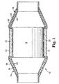
- FIG. 1 shows a catalytic converter 10 typical of the prior art.
- Catalytic converter 10 comprises metal housing 12 with generally conical inlet 14 and outlet 16.
- the housing which is also referred to as a can or a casing, can be made from suitable materials known in the art, and is typically made of metal.
- the housing is made of stainless steel.
- Disposed within housing 12 is a monolithic catalytic element 18 formed of a honeycombed monolithic body either of ceramic or metal.
- the surrounding monolith 18 is a mounting and insulating mat 22.
- inlet 14 and outlet 16 comprise an outer end cone housing 26 and an inner end cone housing 28.
- An insulating material 30 is positioned between outer cone housing 28 and inner cone housing 26.
- inner cone housing 28 is provided in prior art pollution control devices to retain insulating material 30 in position and to prevent insulating material 30 from being damaged by hot exhaust gases passing through the pollution control device.
- the use of inner cone housing 28 adds additional weight, complexity and cost to the pollution control device. It is therefore desired to make the use of inner cone housing 28 unnecessary.
- the present invention provides a free-standing internally insulating liner, and in particular an insulating end cone that does not require use of inner cone housing 28.
- the present invention utilizes a refractory material to provide an inner insulating cone which is resistant to damage caused by exhaust gases as well as resistant to damage caused by mechanical and thermal shock.
- the useful refractory materials are capable of withstanding large gradients in temperature over short periods of time without shattering. Temperature gradients can vary from sub-zero temperatures to over 300°C over the short period of time when a vehicle is started until it reaches cruising speed.
- the present invention uses a composite material having sufficient rigidity to withstand erosion from exhaust gases, and which also provides mechanical and thermal shock resistance.
- the composite material comprises inorganic fibers and/or inorganic particles.
- the composite may optionally include one or more additional binders.
- Fibers useful in the practice of the invention include fibers made from alumina-boria-silica, alumina-silica, alumina-phosphorus pentoxide, zirconia-silica, zirconia-alumina, and alumina.
- the fibers can be formed by processes known in the industry such as by blowing or spinning.
- a useful process is spinning of a sol gel solution.
- Useful fibers are commercially available under the tradenames SAFFIL from ICI Chemicals & Polymers, FIBERMAX from Unifrax Co., ALCEN from Denka, and MAFTECH from Mitsubishi.
- the fibers can be used as fibers or they may be used as a fibrous mat.
- a mat of fibers can be formed by blowing the fibrous material onto a collection screen as is practiced in the nonwoven industry.
- a useful commercially available fiber mat is SAFFIL LD alumina fiber mat from ICI Chemicals & Polymers.
- the cone can also be formed from inorganic particulate materials such as clays, ceramic or glass powders, ceramic or glass beads, and hollow ceramic or glass spheres. Additionally, combinations of fibers and particulates can be used.
- the fibers and particles can act as binders. When the fibers and/or particles are heated to elevated temperatures, e.g., over 500°C, they can melt or be softened sufficiently to bond to other fibers and particles in the cone.
- the fibers and particles can also be sintered. By selecting fibers or particles having different melting points, it is possible to get the achieve various modes of bonding them together. For example, a combination of glass fibers and ceramic fibers can bond because the glass fibers soften and can melt at temperatures lower than the melting temperatures of the ceramic fibers. Additionally, the ceramic fibers can be sintered to other ceramic fibers without substantial melting of the fibers.
- Organic binders can be used to hold the inorganic materials together at room temperature to form the cone. When the cone is heated above about 300°C, the organic binder bums off leaving the cone which can then be fired at elevated temperatures to sinter the inorganic materials together.
- Organic binders are articularly useful for molding and injection molding processes. Useful organic binders include low melting temperatures waxes and polyethylene glycol.
- Inorganic binders can also be used. These binders include sol and sol-gel materials such as alumina sols, colloidal silica suspensions, refractory coatings such as silicon carbide suspensions, and solutions such as a monoaluminum phosphate solution. Colloidal silica suspensions are commercially available from Nalco Co. under the NALCO tradename.
- the inorganic binders can be incorporated into the cone by adding the binders to the composition for forming the cone, infiltrating a formed cone with the sol or suspension, or by brushing a refractory coating or solution onto a surface of the cone.
- Inorganic binders help to stiffen the cones.
- a binder solution or coating is applied only to one surface of the cone, e.g. the inside surface, the inside surface becomes more rigid while the outer surface can remain compressible.
- the binders on the surface can help prevent erosion of the cone from hot exhaust gases.
- adjuvants may also be included to aid in processing such as dispersing aids, wetting agents, thickness, and the like.
- the free-standing fibrous end cone may be formed in a variety of manners such as with a flexible mold, slush molding, press molding, or injection molding.
- Mats of fibers can also be formed in a manner similar to papier-mache in which strips of the fibrous mat are saturated in a binder solution and laid in overlapping fashion on a conical surface.
- each of these methods of forming a free-standing fibrous end cone results in a cone which is resistent to damage from exposure to hot exhaust gases, thermal shock, and road shock.
- the end cone is typically secured within an outer metal end cone.
- the metal end cone is made of high temperature resistant metals such as stainless steel and Inconel.
- the end cone may be secured within the outer metal end cone 26 of a pollution control device in a variety of manners.
- fibrous end cone 40 is compressed against monolith 18 and mounting mat 22 such that the fibrous end cone 40 is restrained from movement.
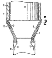
- tabs 42 could be used to restrain fibrous cone 40 within an outer end cone 26, as illustrated in Figure 3.
- Tabs 42 are shown extending from exhaust pipe 44, but could also extend from outer cone 26 or casing 12, for example. Instead of individual tabs 42 as seen in Figure 3, a solid retaining ring (not shown) could also be used.
- fibrous end cone 40 could be restrained within outer end cone 26 in a variety of other manners, depending upon the particular application desired by the user.
- the Hot Shake Test is used to evaluate an end cone for use with a catalytic converter by subjecting a catalytic converter with the end cone to vibration and hot gas from either a gasoline engine (Mode 1) or hot air (Mode 2).
- the two test modes are discussed more fully below.
- MODE 1 - A catalytic converter, with the end cone mounted securely within it, is attached to a solid fixture atop a shaker table (Model TC 208 Electrodynamic Shaker Table from Unholtz-Dickie Corp., Wallingford, CT). The catalytic converter is then attached through a flexible coupling to the exhaust system of a Ford Motor Co. 7.5 liter displacement V-8 gasoline powered internal combustion engine coupled to an Eaton 8121 Eddy-current dynamometer. The converter is tested using an inlet exhaust gas temperature of 900°C at an engine speed of 2200 rpm with a 30.4 kg-meter load, while shaking the converter at 100 Hz and 30 g's acceleration on the shaker table. The converter is tested under these conditions for 25 hours. The converter is then disassembled and the end cone examined visually for signs of disintegration, erosion, and cracking. For a successful test, the end cone should be intact and exhibit no visible damage.
- MODE 2 This test mode is conducted in a manner similar to test Mode 1.
- a catalytic converter and end cone are mounted to a shaker table (available from Unholtz-Dickie) which shakes the converter with an acceleration of 30 g's at a frequency of 100 Hz.
- the heat source is a natural gas burner which supplies an inlet gas temperature of 900°C.
- the converter is subjected to three cycles of heating and cooling (during vibration), where a cycle includes a heating period to attain a gas inlet temperature of 900°C, maintaining the inlet gas temperature at 900°C for an 8-hour period, and cooling to ambient temperature (about 21°C).
- the end cone should not exhibit any visible signs of damage.
- Example 1 illustrates how a ceramic fiber end cone was prepared using a flexible mold and a fiber mixture having an organic binder. (The same composite mixture could also be injection molded).
- a rubber mold was prepared by mixing 10 parts of a room temperature curing rubber (SD-ASTIC K RTV Silicone Rubber Base available from Dow Corning Co.) and 1 part curing agent (SILASTIC K RTV Curing Agent available from Dow Corning Co.). The rubber mixture was molded around a steel cone master having the desired finished dimensions of the fiber cone. The mold was cured for 24 hours at room temperature (approximately 21°C).
- SD-ASTIC K RTV Silicone Rubber Base available from Dow Corning Co.
- SILASTIC K RTV Curing Agent available from Dow Corning Co.
- Glass fibers (6.35 mm long S-2 Glass Fibers available from Owens-Corning Fiberglas Corp.) were heat cleaned and crushed to a fiber length of about 0.5 mm. Ceramic fibers (SAFFIL ceramic fibers from ICI Chemicals & Polymers Ltd.) were milled to a length of about 0.25 mm. A mixture of fibers was prepared by mixing 37.8 grams each of the crushed glass and ceramic fibers. The fiber mixture was then poured into a planetary mixer (Model LDM-1 gallon Ross mixer available from Charles Ross & Son Co.) containing 150 grams of binder (polyethylene glycol 1000 m.w. available from Aldrich Chemical Inc.) and 0.75 gram of a dispersing aid (KD-5 dispersant available from ICI Americas).
- a planetary mixer Model LDM-1 gallon Ross mixer available from Charles Ross & Son Co.
- binder polyethylene glycol 1000 m.w. available from Aldrich Chemical Inc.
- KD-5 dispersant available from ICI Americas
- the mixture was heated to 100°C in the mixer to melt the binder, and then mixed under a vacuum of 25 mm Hg for about 30 minutes.
- the resulting fiber-binder mixture was poured into the rubber mold which had been heated to 40°C.
- the filled mold was then placed in a vacuum chamber affixed to a vibrating table (SYTRON vibration table from FMC Corp.)
- the vacuum chamber was evacuated to 30 mm Hg, and the table was vibrated for 5 minutes to de-aerate the mixture and to enhance the flow of the mixture into the mold.
- the mold was then removed from the vacuum chamber and cooled to room temperature.
- the hardened fiber cone was removed from the mold, packed in a bed of hollow alumina beads (1.5 mm diameter beads available from Microcel Technologies, Inc.), and heated to 250°C for about 3 hours. The beads were used to prevent the cone from slumping and becoming deformed while a substantial portion of the binder baked out. The cone was then removed from the bed and fired in a kiln at 1100°C for 4 hours to bond the fibers in the cone. The cone was cooled to room temperature, inserted into a metal cone housing for a catalytic converter, and subject to the Hot Shake Test - Mode 2 described above. After testing, the cone was found to be intact and exhibited no cracking or other visible signs of erosion or disintegration.
- hollow alumina beads 1.5 mm diameter beads available from Microcel Technologies, Inc.
- Examples 2-4 illustrate how a ceramic end cone was prepared using a slurry of water and ceramic fibers.
- a conical mold was prepared by cutting and fabricating a sheet of perforated sheet metal to the shape of a catalytic converter end cone. The mold was then covered with a wire screen (25 mesh). The large diameter end of the cone was sealed by taping the end shut with filament tape, and the small diameter end of the mold was attached to a 3.8 mm diameter vacuum hose of a vacuum cleaner (Shopvac available from Sears).
- Example 2 a slurry was prepared by mixing 14 liters of tap water, 200 grams of ceramic fibers (7000M ceramic fibers available from Unifrax Co., Niagara Falls, N.Y.) with an air mixer for about 10 minutes. With continued mixing, 2 liters of a colloidal silica suspension (NALCO 2327 available from Nalco Chemical Co.) were added and dispersed.
- ceramic fibers 7000M ceramic fibers available from Unifrax Co., Niagara Falls, N.Y.
- NALCO 2327 available from Nalco Chemical Co.
- the mold was then placed in the slurry and the vacuum was turned on for approximately 5 seconds.
- the mold was immediately removed after the vacuum was turned off, and a 6.3 mm thick layer of fibers had been deposited on the cone.
- the fiber cone was removed from the mold and dried at 100°C for about 2 hours.
- Fiber cones for Examples 3-4 were prepared as for Example 2, except that a coating was applied with a brush to the inside surface of each cone.
- the coatings of Examples 3-4 made the inner surfaces of the cones more rigid while the outer surfaces of the cones remained compressible.
- other coatings such as a Silicon Carbide suspension (available from ZYP Coatings, Inc.) could also be used.
- the coatings for each example were as follows:
- Example 5 illustrates how a ceramic end cone was prepared using a ceramic fiber mat material.
- a ceramic fiber mat (SAFFIL Type LD Mat available from ICI Chemicals and Polymers) was cut into strips measuring approximately 5.1 cm by 10.2 cm. The strips were dipped into a colloidal silica suspension (NALCO 2327), and applied on the inside surface of an outer metal cone portion of a catalytic converter. (The outer end cone acted as a forming mold). The strips were overlapped and layered to form cone having a thickness of about 6.35 mm. An inner cone of the catalytic converter (acting as an interior mold for the strips) was then forced over the layers to sandwich the layers of mat material between the exterior and interior metal end cones.
- SAFFIL Type LD Mat available from ICI Chemicals and Polymers
- the assembly was dried at 100°C for approximately 5 hours in an air oven.
- the inner metal cone was then removed, and the outer metal cone with the layered mat was heated to 900°C for about 1 hour to form a rigid fiber cone.
- the fiber cone was then removed and subjected to the Hot Shake Test - Mode 1.
- the cone did not exhibit any cracking, disintegration, or erosion.
- Example 1-5 demonstrate that the free standing fiber composite end cone can withstand the exhaust gas flows and the vibrational shaking of an exhaust after-treatment environment.
- the free-standing fiber end cone may also be formed by additional methods, such as injection molding.
Landscapes
- Engineering & Computer Science (AREA)
- Chemical & Material Sciences (AREA)
- Mechanical Engineering (AREA)
- Chemical Kinetics & Catalysis (AREA)
- General Engineering & Computer Science (AREA)
- Combustion & Propulsion (AREA)
- Toxicology (AREA)
- Health & Medical Sciences (AREA)
- Exhaust Gas After Treatment (AREA)
- Exhaust Silencers (AREA)
- Catalysts (AREA)
- Filtering Materials (AREA)
- Processes For Solid Components From Exhaust (AREA)
- Physical Or Chemical Processes And Apparatus (AREA)
Applications Claiming Priority (3)
| Application Number | Priority Date | Filing Date | Title |
|---|---|---|---|
| US08/665,606 US6726884B1 (en) | 1996-06-18 | 1996-06-18 | Free-standing internally insulating liner |
| US665606 | 1996-06-18 | ||
| PCT/US1996/016323 WO1997048890A1 (en) | 1996-06-18 | 1996-10-15 | Free-standing internally insulating liner |
Publications (2)
| Publication Number | Publication Date |
|---|---|
| EP0906496A1 EP0906496A1 (en) | 1999-04-07 |
| EP0906496B1 true EP0906496B1 (en) | 2002-03-27 |
Family
ID=24670803
Family Applications (1)
| Application Number | Title | Priority Date | Filing Date |
|---|---|---|---|
| EP96936388A Expired - Lifetime EP0906496B1 (en) | 1996-06-18 | 1996-10-15 | Free-standing internally insulating liner |
Country Status (8)
| Country | Link |
|---|---|
| US (2) | US6726884B1 (enExample) |
| EP (1) | EP0906496B1 (enExample) |
| JP (1) | JP2002514280A (enExample) |
| AU (1) | AU7440296A (enExample) |
| CA (1) | CA2256769C (enExample) |
| DE (1) | DE69620260T2 (enExample) |
| ES (1) | ES2170882T3 (enExample) |
| WO (1) | WO1997048890A1 (enExample) |
Cited By (9)
| Publication number | Priority date | Publication date | Assignee | Title |
|---|---|---|---|---|
| US6946013B2 (en) | 2002-10-28 | 2005-09-20 | Geo2 Technologies, Inc. | Ceramic exhaust filter |
| US7211232B1 (en) | 2005-11-07 | 2007-05-01 | Geo2 Technologies, Inc. | Refractory exhaust filtering method and apparatus |
| US7444805B2 (en) | 2005-12-30 | 2008-11-04 | Geo2 Technologies, Inc. | Substantially fibrous refractory device for cleaning a fluid |
| US7563415B2 (en) | 2006-03-03 | 2009-07-21 | Geo2 Technologies, Inc | Catalytic exhaust filter device |
| US7574796B2 (en) | 2002-10-28 | 2009-08-18 | Geo2 Technologies, Inc. | Nonwoven composites and related products and methods |
| US7582270B2 (en) | 2002-10-28 | 2009-09-01 | Geo2 Technologies, Inc. | Multi-functional substantially fibrous mullite filtration substrates and devices |
| US7682578B2 (en) | 2005-11-07 | 2010-03-23 | Geo2 Technologies, Inc. | Device for catalytically reducing exhaust |
| US7682577B2 (en) | 2005-11-07 | 2010-03-23 | Geo2 Technologies, Inc. | Catalytic exhaust device for simplified installation or replacement |
| US7722828B2 (en) | 2005-12-30 | 2010-05-25 | Geo2 Technologies, Inc. | Catalytic fibrous exhaust system and method for catalyzing an exhaust gas |
Families Citing this family (67)
| Publication number | Priority date | Publication date | Assignee | Title |
|---|---|---|---|---|
| GB9915939D0 (en) | 1999-07-08 | 1999-09-08 | Johnson Matthey Plc | Improvements in pollution control |
| US7524546B2 (en) * | 2000-12-28 | 2009-04-28 | 3M Innovative Properties Company | Thermal insulating material and pollution control device using the same |
| US20030086832A1 (en) * | 2001-11-02 | 2003-05-08 | Turek Alan G. | End cones for exhaust emission control devices and methods of making |
| US7572311B2 (en) | 2002-10-28 | 2009-08-11 | Geo2 Technologies, Inc. | Highly porous mullite particulate filter substrate |
| KR101148724B1 (ko) | 2003-01-22 | 2012-05-29 | 쓰리엠 이노베이티브 프로퍼티즈 컴파니 | 성형 3차원 절연체 |
| US20040197242A1 (en) * | 2003-04-04 | 2004-10-07 | Ian Holden | Mid-bed catalyst sensor with silica insulation |
| US20050036923A1 (en) * | 2003-07-31 | 2005-02-17 | Brisbin Ronald S. | End cone construction for catalytic converters and method for making same |
| KR101058770B1 (ko) * | 2004-06-29 | 2011-08-24 | 유니프랙스 아이 엘엘씨 | 배기 가스 처리 장치 및 배기 가스 처리 장치의 제조 방법 |
| US7441334B2 (en) * | 2005-05-02 | 2008-10-28 | Fleetguard, Inc. | Exhaust system with spin-capture retention of aftertreatment element |
| US7503956B2 (en) * | 2005-10-25 | 2009-03-17 | Caterpillar Inc. | Exhaust treatment device with adjustable retention collar |
| US7451849B1 (en) | 2005-11-07 | 2008-11-18 | Geo2 Technologies, Inc. | Substantially fibrous exhaust screening system for motor vehicles |
| AU2006313594B2 (en) * | 2005-11-10 | 2011-06-09 | Morgan Advanced Materials Plc | High temperature resistant fibres |
| US20070113547A1 (en) * | 2005-11-21 | 2007-05-24 | Thaler David M | Exhaust treatment device with condensate gate |
| CN101473118B (zh) * | 2006-06-15 | 2013-05-29 | 3M创新有限公司 | 绝缘双壁排气系统部件及其制造方法 |
| EP2035666A4 (en) * | 2006-06-15 | 2010-05-19 | 3M Innovative Properties Co | ISOLATED DOUBLE-WALL EXHAUST SYSTEM COMPONENT AND METHOD FOR MANUFACTURING THE SAME |
| WO2008073113A1 (en) * | 2006-12-15 | 2008-06-19 | Doben Limited | Multi-passage heater assembly |
| JP5014113B2 (ja) * | 2007-01-26 | 2012-08-29 | イビデン株式会社 | シート材、その製造方法、排気ガス処理装置および消音装置 |
| US8256060B2 (en) * | 2007-01-30 | 2012-09-04 | Donaldson Company, Inc. | Apparatus for cleaning exhaust aftertreatment devices and methods |
| CN102154915B (zh) * | 2007-02-19 | 2014-04-23 | 3M创新有限公司 | 柔性纤维质材料、污染控制装置及其制造方法 |
| US7582141B2 (en) * | 2007-05-31 | 2009-09-01 | International Truck Intellectual Property Company, Llc | Diesel particulate filter pulse cleaner flow director system and method |
| DE102007026712A1 (de) * | 2007-06-06 | 2008-12-11 | Uhde Gmbh | Vorrichtung und Verfahren für katalytische Gasphasenreaktionen sowie deren Verwendung |
| PL2173981T3 (pl) * | 2007-06-13 | 2019-06-28 | 3M Innovative Properties Company | Odporny materiał montażowy oraz sposób jego wytwarzania i stosowania |
| EP2487342B1 (en) * | 2007-06-13 | 2018-04-18 | 3M Innovative Properties Company | Erosion resistant mounting material and method of making and using the same |
| US20100037423A1 (en) * | 2008-07-10 | 2010-02-18 | Herman John T | Apparatus for Cleaning Exhaust Aftertreatment Devices and Methods |
| EP2328674B1 (en) * | 2008-08-29 | 2014-04-23 | Unifrax I LLC | Mounting mat with flexible edge protection and exhaust gas treatment device incorporating the mounting mat |
| DE102008059930A1 (de) * | 2008-12-02 | 2010-06-10 | Uhde Gmbh | Vorrichtung und Verfahren für katalytische Gasphasenreaktionen sowie deren Verwendung |
| US8066792B2 (en) * | 2008-12-03 | 2011-11-29 | Cummins Filtration Ip, Inc. | Apparatus, system, and method for insulating an exhaust aftertreatment component |
| KR101784013B1 (ko) | 2008-12-15 | 2017-10-10 | 유니프랙스 아이 엘엘씨 | 세라믹 허니콤 구조체의 스킨 코팅 |
| AU2009333811B2 (en) * | 2009-01-05 | 2013-08-22 | Unifrax I Llc | High strength biosoluble inorganic fiber insulation mat |
| EP2406073B1 (en) * | 2009-03-13 | 2020-04-22 | 3M Innovative Properties Company | Mat and devices with the same |
| CN102459834B (zh) * | 2009-04-17 | 2017-02-08 | 尤尼弗瑞克斯 I 有限责任公司 | 排气处理装置 |
| GB0906837D0 (en) | 2009-04-21 | 2009-06-03 | Saffil Automotive Ltd | Mats |
| US9358749B2 (en) | 2009-07-09 | 2016-06-07 | 3M Innovative Properties Company | Tubular, continuous, seamless, compressible, resilient mounting articles and pollution control devices comprising the same |
| WO2011019377A2 (en) * | 2009-08-10 | 2011-02-17 | Unifrax I Llc | Variable basis weight mounting mat or pre-form and exhaust gas treatment device |
| US9174169B2 (en) | 2009-08-14 | 2015-11-03 | Unifrax I Llc | Mounting mat for exhaust gas treatment device |
| CN102686843B (zh) * | 2009-08-14 | 2015-04-01 | 尤尼弗瑞克斯I有限责任公司 | 多层基底支承体和排气处理装置 |
| US8071040B2 (en) * | 2009-09-23 | 2011-12-06 | Unifax I LLC | Low shear mounting mat for pollution control devices |
| CN102575552B (zh) * | 2009-09-24 | 2016-03-16 | 尤尼弗瑞克斯I有限责任公司 | 多层垫和废气处理装置 |
| ES2615496T3 (es) | 2009-12-01 | 2017-06-07 | Unifrax Emission Control Europe Ltd. | Esterilla de montaje |
| CA2782413C (en) * | 2009-12-17 | 2017-12-05 | Unifrax I Llc | Multilayer mounting mat for pollution control devices |
| CN102753795B (zh) * | 2009-12-17 | 2016-02-17 | 尤尼弗瑞克斯I有限责任公司 | 微球体在废气处理装置安装垫中的用途 |
| US20110150717A1 (en) * | 2009-12-17 | 2011-06-23 | Unifrax I Llc | Mounting mat for exhaust gas treatment device |
| US8956432B2 (en) | 2010-06-18 | 2015-02-17 | Retro Filters LLC | Reusable aftermarket particulate collection member for otherwise conventional consumer floor vacuum cleaners |
| US8336673B2 (en) * | 2010-07-07 | 2012-12-25 | Bay Industries Inc. | Muffler, muffler insert, and methods and apparatus for making |
| US8765069B2 (en) | 2010-08-12 | 2014-07-01 | Unifrax I Llc | Exhaust gas treatment device |
| EP2603676B1 (en) | 2010-08-13 | 2016-03-23 | Unifrax I LLC | Mounting mat with flexible edge protection and exhaust gas treatment device incorporating the mounting mat |
| EP2638261A4 (en) | 2010-11-11 | 2014-08-06 | Unifrax I Llc | SUPPORT MAT AND DEVICE FOR TREATING EXHAUST GASES |
| US9924564B2 (en) | 2010-11-11 | 2018-03-20 | Unifrax I Llc | Heated mat and exhaust gas treatment device |
| DE102011005155A1 (de) * | 2011-03-04 | 2012-09-06 | J. Eberspächer GmbH & Co. KG | Abgasanlagenkomponente |
| JP5780515B2 (ja) * | 2011-06-03 | 2015-09-16 | 国立研究開発法人産業技術総合研究所 | 排気ガス浄化フィルタの粒子状物質蓄積量計測方法 |
| EA025292B1 (ru) * | 2011-08-02 | 2016-12-30 | Басф Се | Реактор для проведения автотермического газофазного дегидрирования |
| EP2764222B1 (en) | 2011-09-22 | 2018-09-05 | 3M Innovative Properties Company | Thermal insulating wrap for exhaust systems and method of manufacturing the same |
| DE102012208449C5 (de) | 2012-05-21 | 2016-03-03 | Eberspächer Exhaust Technology GmbH & Co. KG | Abgasnachbehandlungseinrichtung und zugehöriges Herstellungsverfahren |
| US10508583B2 (en) | 2012-08-30 | 2019-12-17 | Bosal Emission Control Systems Nv | Composite exhaust element |
| WO2014160665A1 (en) | 2013-03-27 | 2014-10-02 | 3M Innovative Properties Company | Thermally insulated components |
| JP2013155750A (ja) * | 2013-05-20 | 2013-08-15 | Ibiden Co Ltd | 触媒コンバータ用保持シール材 |
| MX378454B (es) | 2013-07-22 | 2025-03-10 | Morgan Advanced Mat Plc | Composiciones de fibras inorgànicas. |
| EP3084074B1 (en) | 2013-12-19 | 2018-07-04 | 3M Innovative Properties Company | Using recycled waste water to make nonwoven fibrous materials suitable for use in a pollution control device or in a firestop |
| JP6294068B2 (ja) * | 2013-12-19 | 2018-03-14 | 株式会社ユタカ技研 | 排気系部品の遮熱カバー及びその製造方法 |
| KR20170118679A (ko) | 2015-02-24 | 2017-10-25 | 유니프랙스 아이 엘엘씨 | 내고온성 절연 매트 |
| US9938872B2 (en) | 2015-06-09 | 2018-04-10 | Bay Fabrication, Inc. | Muffler insert, and systems, methods and apparatus for making |
| US10894737B2 (en) | 2016-01-15 | 2021-01-19 | Thermal Ceramics Uk Limited | Apparatus and method for forming melt-formed inorganic fibres |
| GB201616662D0 (en) | 2016-09-30 | 2016-11-16 | Morgan Advanced Materials Plc | Inorganic Fibre compositions |
| US10450937B2 (en) | 2016-12-21 | 2019-10-22 | Tenneco Automotive Operating Company Inc. | Apparatus and method of producing insulation preform with graded porosity |
| CN112955268B (zh) | 2018-10-29 | 2022-07-01 | 卡特里奇有限公司 | 热增强的排气端口衬套 |
| JP7616978B2 (ja) | 2021-10-29 | 2025-01-17 | フタバ産業株式会社 | 排気ガス浄化装置 |
| USD1051081S1 (en) * | 2022-11-25 | 2024-11-12 | Ap Systems Inc. | Exhaust wall liner for semiconductor manufacturing apparatus |
Family Cites Families (55)
| Publication number | Priority date | Publication date | Assignee | Title |
|---|---|---|---|---|
| US3250833A (en) * | 1959-05-29 | 1966-05-10 | Avco Corp | Process of making an impregnated ceramic |
| US3166467A (en) * | 1962-10-18 | 1965-01-19 | Diamond National Corp | Method for producing molded pulp articles |
| US3458329A (en) * | 1963-02-13 | 1969-07-29 | Minnesota Mining & Mfg | Ceramic greensheets |
| US3456914A (en) * | 1965-10-23 | 1969-07-22 | Johns Manville | Inorganic fiber riser sleeves |
| US3488723A (en) | 1966-07-05 | 1970-01-06 | Owens Corning Fiberglass Corp | Acoustical material for high temperature application |
| US3655863A (en) * | 1970-01-09 | 1972-04-11 | Monsanto Co | Method of making a contoured composite product |
| NL7302006A (enExample) * | 1972-02-29 | 1973-08-31 | ||
| US3801289A (en) | 1972-05-19 | 1974-04-02 | Corning Glass Works | Catalytic converter |
| GB1455563A (en) | 1972-11-29 | 1976-11-17 | Ici Ltd | Fibrous mater-als |
| DE2300982A1 (de) | 1973-01-10 | 1974-07-11 | Volkswagenwerk Ag | Vorrichtung zur halterung eines keramischen koerpers |
| US4011651A (en) | 1973-03-01 | 1977-03-15 | Imperial Chemical Industries Limited | Fibre masses |
| DE2314465C3 (de) * | 1973-03-23 | 1978-12-07 | Volkswagenwerk Ag, 3180 Wolfsburg | Einrichtung zur katalytischen Abgasreinigung |
| US3916057A (en) * | 1973-08-31 | 1975-10-28 | Minnesota Mining & Mfg | Intumescent sheet material |
| GB1474904A (en) * | 1973-09-05 | 1977-05-25 | Rubery Owen & Co Ltd | Method of forming a casing or housing for a catalytic block for use in an exhaust system for an internal combustion engine |
| GB1488649A (en) | 1973-10-30 | 1977-10-12 | Ici Ltd | Needled fibrous structure |
| US4431449A (en) | 1977-09-26 | 1984-02-14 | Minnesota Mining And Manufacturing Company | Infiltrated molded articles of spherical non-refractory metal powders |
| US4181514A (en) | 1978-02-14 | 1980-01-01 | Huyck Corporation | Stitch knitted filters for high temperature fluids and method of making them |
| DE2907767C2 (de) * | 1979-02-28 | 1986-07-03 | Knorr-Bremse AG, 8000 München | Schutzvorrichtung, insbesondere für Abgasrohre von Verbrennungsmotoren |
| US4376675A (en) | 1979-05-24 | 1983-03-15 | Whatman Reeve Angel Limited | Method of manufacturing an inorganic fiber filter tube and product |
| US4305992A (en) * | 1979-11-28 | 1981-12-15 | Minnesota Mining And Manufacturing Company | Intumescent sheet material |
| US4385135A (en) * | 1982-05-26 | 1983-05-24 | Minnesota Mining And Manufacturing Company | Intumescent sheet material containing low density fillers |
| GB2143902B (en) | 1983-01-20 | 1987-04-15 | Honda Motor Co Ltd | Heat and sound insulating apparatus |
| GB2160467B (en) * | 1984-06-22 | 1987-09-23 | Rolls Royce | Moulding of composite materials |
| DE3432283A1 (de) | 1984-09-01 | 1986-03-13 | LEISTRITZ Maschinenfabrik GmbH, 8500 Nürnberg | Katalytische abgasentgiftungseinrichtung |
| FR2572332B1 (fr) * | 1984-10-25 | 1986-12-26 | Prod Cellulosiques Isolants | Piece isolante de formes variees, formee par un empilement de nappes en fibres resistant a haute temperature et procede de fabrication |
| GB8504239D0 (en) | 1985-02-19 | 1985-03-20 | W F J Refractories Ltd | Use of fibrous materials |
| FR2585071B1 (fr) | 1985-07-16 | 1987-11-27 | Peugeot Cycles | Pot d'echappement pour vehicule automobile ou analogue |
| DE3626728A1 (de) | 1986-08-07 | 1988-02-18 | Leistritz Ag | Abgasreinigungsvorrichtung fuer kraftfahrzeuge |
| DE3700070A1 (de) * | 1987-01-02 | 1988-07-14 | Eberspaecher J | Vorrichtung fuer die katalytische reinigung von fahrzeugmotor-abgasen |
| CA1317978C (en) * | 1987-06-05 | 1993-05-18 | Thomas E. Wood | Microcrystalline alumina-based ceramic articles |
| US4865818A (en) * | 1987-08-17 | 1989-09-12 | Minnesota Mining And Manufacturing Co. | Catalytic converter for automotive exhaust system |
| US4929429A (en) | 1988-02-11 | 1990-05-29 | Minnesota Mining And Manufacturing Company | Catalytic converter |
| US5028397A (en) | 1988-02-11 | 1991-07-02 | Minnesota Mining And Manufacturing Company | Catalytic converter |
| US5242871A (en) * | 1988-02-29 | 1993-09-07 | Nippon Pillar Packing Co., Ltd. | Heat-resistant expansion member |
| SE463513B (sv) * | 1988-07-21 | 1990-12-03 | Eka Nobel Ab | Komposition foer beredning av en vaermeisolerande keramisk belaeggning paa en metall, foerfarande foer dess framstaellning, anvaendning av densamma samt avgasroer foersett med en belaeggning av en saadan komposition |
| US5008086A (en) * | 1988-10-28 | 1991-04-16 | Minnesota Mining And Manufacturing Company | Erosion resistant mounting composite for catalytic converter |
| US4999168A (en) * | 1989-05-01 | 1991-03-12 | The Carborundum Company | Crack resistant intumescent sheet material |
| US5024289A (en) * | 1989-09-14 | 1991-06-18 | Minnesota Mining And Manufacturing Company | Insulated double-walled exhaust pipe |
| US5190610A (en) * | 1989-11-08 | 1993-03-02 | Ek Roger B | Method for producing a ceramic fiber-metal laminate |
| US5078822A (en) * | 1989-11-14 | 1992-01-07 | Hodges Michael F | Method for making refractory lined duct and duct formed thereby |
| GB9011849D0 (en) | 1990-05-26 | 1990-07-18 | Fibre Tech Ltd | Catalytic converters |
| US5151253A (en) * | 1991-04-18 | 1992-09-29 | Minnesota Mining And Manufacturing Company | Catalytic converter having a monolith mounting of which is comprised of partially dehydrated vermiculite flakes |
| US5254410A (en) * | 1991-04-18 | 1993-10-19 | Minnesota Mining & Manufacturing Company | Partially dehydrated vermiculite flakes and method of making same |
| US5250269A (en) * | 1992-05-21 | 1993-10-05 | Minnesota Mining And Manufacturing Company | Catalytic converter having a metallic monolith mounted by a heat-insulating mat of refractory ceramic fibers |
| EP0678128B1 (en) * | 1993-01-07 | 1996-09-25 | Minnesota Mining And Manufacturing Company | Flexible nonwoven mat |
| US5290522A (en) * | 1993-01-07 | 1994-03-01 | Minnesota Mining And Manufacturing Company | Catalytic converter mounting mat |
| US5332609A (en) * | 1993-03-25 | 1994-07-26 | Minnesota Mining And Manufacturing Company | Intumescent mounting mat |
| FR2703105B1 (fr) | 1993-03-26 | 1995-06-16 | Ecia Equip Composants Ind Auto | Dispositif de purification catalytique des gaz d'echappement d'un moteur, notamment de vehicule automobile. |
| US5866079A (en) | 1993-09-03 | 1999-02-02 | Ngk Insulators, Ltd. | Ceramic honeycomb catalytic converter |
| US5419127A (en) | 1993-11-22 | 1995-05-30 | Soundwich Inc | Insulated damped exhaust manifold |
| US5408828A (en) | 1993-12-10 | 1995-04-25 | General Motors Corporation | Integral cast diffuser for a catalytic converter |
| US5404716A (en) | 1994-02-24 | 1995-04-11 | Caterpillar Inc. | Internally insulated gas manifold |
| US5523059A (en) * | 1995-06-30 | 1996-06-04 | Minnesota Mining And Manufacturing Company | Intumescent sheet material with glass fibers |
| US6010668A (en) * | 1998-02-17 | 2000-01-04 | General Motors Corporation | End cone assembly and method for catalytic converter |
| US6613296B1 (en) * | 2000-01-31 | 2003-09-02 | Delphi Technologies, Inc. | Relieved support material for catalytic converter and the process of making the same |
-
1996
- 1996-06-18 US US08/665,606 patent/US6726884B1/en not_active Expired - Fee Related
- 1996-10-15 EP EP96936388A patent/EP0906496B1/en not_active Expired - Lifetime
- 1996-10-15 CA CA002256769A patent/CA2256769C/en not_active Expired - Fee Related
- 1996-10-15 ES ES96936388T patent/ES2170882T3/es not_active Expired - Lifetime
- 1996-10-15 AU AU74402/96A patent/AU7440296A/en not_active Abandoned
- 1996-10-15 JP JP50288998A patent/JP2002514280A/ja not_active Ceased
- 1996-10-15 DE DE69620260T patent/DE69620260T2/de not_active Expired - Fee Related
- 1996-10-15 WO PCT/US1996/016323 patent/WO1997048890A1/en not_active Ceased
-
2003
- 2003-12-22 US US10/744,263 patent/US20040137175A1/en not_active Abandoned
Cited By (9)
| Publication number | Priority date | Publication date | Assignee | Title |
|---|---|---|---|---|
| US6946013B2 (en) | 2002-10-28 | 2005-09-20 | Geo2 Technologies, Inc. | Ceramic exhaust filter |
| US7574796B2 (en) | 2002-10-28 | 2009-08-18 | Geo2 Technologies, Inc. | Nonwoven composites and related products and methods |
| US7582270B2 (en) | 2002-10-28 | 2009-09-01 | Geo2 Technologies, Inc. | Multi-functional substantially fibrous mullite filtration substrates and devices |
| US7211232B1 (en) | 2005-11-07 | 2007-05-01 | Geo2 Technologies, Inc. | Refractory exhaust filtering method and apparatus |
| US7682578B2 (en) | 2005-11-07 | 2010-03-23 | Geo2 Technologies, Inc. | Device for catalytically reducing exhaust |
| US7682577B2 (en) | 2005-11-07 | 2010-03-23 | Geo2 Technologies, Inc. | Catalytic exhaust device for simplified installation or replacement |
| US7444805B2 (en) | 2005-12-30 | 2008-11-04 | Geo2 Technologies, Inc. | Substantially fibrous refractory device for cleaning a fluid |
| US7722828B2 (en) | 2005-12-30 | 2010-05-25 | Geo2 Technologies, Inc. | Catalytic fibrous exhaust system and method for catalyzing an exhaust gas |
| US7563415B2 (en) | 2006-03-03 | 2009-07-21 | Geo2 Technologies, Inc | Catalytic exhaust filter device |
Also Published As
| Publication number | Publication date |
|---|---|
| DE69620260D1 (de) | 2002-05-02 |
| EP0906496A1 (en) | 1999-04-07 |
| CA2256769C (en) | 2004-07-27 |
| US6726884B1 (en) | 2004-04-27 |
| AU7440296A (en) | 1998-01-07 |
| CA2256769A1 (en) | 1997-12-24 |
| WO1997048890A1 (en) | 1997-12-24 |
| US20040137175A1 (en) | 2004-07-15 |
| DE69620260T2 (de) | 2002-11-07 |
| ES2170882T3 (es) | 2002-08-16 |
| JP2002514280A (ja) | 2002-05-14 |
Similar Documents
| Publication | Publication Date | Title |
|---|---|---|
| EP0906496B1 (en) | Free-standing internally insulating liner | |
| CA2353566C (en) | Amorphous non-intumescent inorganic fiber mat for low temperature exhaust gas treatment devices | |
| AU743264C (en) | Support element for fragile structures such as catalytic converters | |
| JP5484292B2 (ja) | 排気ガス処理装置及びその製造方法 | |
| EP1371406B1 (en) | Honeycomb structural body | |
| CA2500380C (en) | Exhaust gas treatment device and method for making the same | |
| JP4511070B2 (ja) | ハニカム構造体及びそのアッセンブリ | |
| JP2013501892A (ja) | 可変基本質量取付けマットまたはプレフォームおよび排気ガス処理装置 | |
| CN102753795B (zh) | 微球体在废气处理装置安装垫中的用途 | |
| KR100540028B1 (ko) | 자립형내부단열라이너 | |
| Gulati | New developments in catalytic converter durability | |
| MXPA98010512A (en) | Internal insulating coating self-treatment | |
| US8404187B1 (en) | Support element for fragile structures such as catalytic converters | |
| US9358749B2 (en) | Tubular, continuous, seamless, compressible, resilient mounting articles and pollution control devices comprising the same |
Legal Events
| Date | Code | Title | Description |
|---|---|---|---|
| PUAI | Public reference made under article 153(3) epc to a published international application that has entered the european phase |
Free format text: ORIGINAL CODE: 0009012 |
|
| 17P | Request for examination filed |
Effective date: 19981215 |
|
| AK | Designated contracting states |
Kind code of ref document: A1 Designated state(s): DE ES FR GB IT |
|
| 17Q | First examination report despatched |
Effective date: 20000824 |
|
| GRAG | Despatch of communication of intention to grant |
Free format text: ORIGINAL CODE: EPIDOS AGRA |
|
| RBV | Designated contracting states (corrected) |
Designated state(s): DE ES FR GB IT |
|
| GRAG | Despatch of communication of intention to grant |
Free format text: ORIGINAL CODE: EPIDOS AGRA |
|
| GRAH | Despatch of communication of intention to grant a patent |
Free format text: ORIGINAL CODE: EPIDOS IGRA |
|
| GRAH | Despatch of communication of intention to grant a patent |
Free format text: ORIGINAL CODE: EPIDOS IGRA |
|
| REG | Reference to a national code |
Ref country code: GB Ref legal event code: IF02 |
|
| GRAA | (expected) grant |
Free format text: ORIGINAL CODE: 0009210 |
|
| AK | Designated contracting states |
Kind code of ref document: B1 Designated state(s): DE ES FR GB IT |
|
| REF | Corresponds to: |
Ref document number: 69620260 Country of ref document: DE Date of ref document: 20020502 |
|
| ET | Fr: translation filed | ||
| REG | Reference to a national code |
Ref country code: ES Ref legal event code: FG2A Ref document number: 2170882 Country of ref document: ES Kind code of ref document: T3 |
|
| PLBE | No opposition filed within time limit |
Free format text: ORIGINAL CODE: 0009261 |
|
| STAA | Information on the status of an ep patent application or granted ep patent |
Free format text: STATUS: NO OPPOSITION FILED WITHIN TIME LIMIT |
|
| 26N | No opposition filed |
Effective date: 20021230 |
|
| PGFP | Annual fee paid to national office [announced via postgrant information from national office to epo] |
Ref country code: ES Payment date: 20061026 Year of fee payment: 11 |
|
| PGFP | Annual fee paid to national office [announced via postgrant information from national office to epo] |
Ref country code: DE Payment date: 20071130 Year of fee payment: 12 |
|
| PGFP | Annual fee paid to national office [announced via postgrant information from national office to epo] |
Ref country code: IT Payment date: 20071029 Year of fee payment: 12 |
|
| PGFP | Annual fee paid to national office [announced via postgrant information from national office to epo] |
Ref country code: GB Payment date: 20071029 Year of fee payment: 12 Ref country code: FR Payment date: 20071017 Year of fee payment: 12 |
|
| REG | Reference to a national code |
Ref country code: ES Ref legal event code: FD2A Effective date: 20071016 |
|
| PG25 | Lapsed in a contracting state [announced via postgrant information from national office to epo] |
Ref country code: ES Free format text: LAPSE BECAUSE OF NON-PAYMENT OF DUE FEES Effective date: 20071016 |
|
| GBPC | Gb: european patent ceased through non-payment of renewal fee |
Effective date: 20081015 |
|
| REG | Reference to a national code |
Ref country code: FR Ref legal event code: ST Effective date: 20090630 |
|
| PG25 | Lapsed in a contracting state [announced via postgrant information from national office to epo] |
Ref country code: IT Free format text: LAPSE BECAUSE OF NON-PAYMENT OF DUE FEES Effective date: 20081015 Ref country code: DE Free format text: LAPSE BECAUSE OF NON-PAYMENT OF DUE FEES Effective date: 20090501 |
|
| PG25 | Lapsed in a contracting state [announced via postgrant information from national office to epo] |
Ref country code: FR Free format text: LAPSE BECAUSE OF NON-PAYMENT OF DUE FEES Effective date: 20081031 |
|
| PG25 | Lapsed in a contracting state [announced via postgrant information from national office to epo] |
Ref country code: GB Free format text: LAPSE BECAUSE OF NON-PAYMENT OF DUE FEES Effective date: 20081015 |