EP0906234B1 - Transportation system for rider propelled vehicles - Google Patents
Transportation system for rider propelled vehicles Download PDFInfo
- Publication number
- EP0906234B1 EP0906234B1 EP95938875A EP95938875A EP0906234B1 EP 0906234 B1 EP0906234 B1 EP 0906234B1 EP 95938875 A EP95938875 A EP 95938875A EP 95938875 A EP95938875 A EP 95938875A EP 0906234 B1 EP0906234 B1 EP 0906234B1
- Authority
- EP
- European Patent Office
- Prior art keywords
- air
- passage structure
- transportation
- passageways
- transportation system
- Prior art date
- Legal status (The legal status is an assumption and is not a legal conclusion. Google has not performed a legal analysis and makes no representation as to the accuracy of the status listed.)
- Expired - Lifetime
Links
- 238000009434 installation Methods 0.000 claims description 8
- 239000000463 material Substances 0.000 claims description 5
- 238000001816 cooling Methods 0.000 claims description 4
- 238000010438 heat treatment Methods 0.000 claims description 4
- 239000004033 plastic Substances 0.000 claims description 4
- 229920003023 plastic Polymers 0.000 claims description 4
- 238000001914 filtration Methods 0.000 claims description 3
- 230000003750 conditioning effect Effects 0.000 claims 2
- 230000003028 elevating effect Effects 0.000 claims 2
- 238000013461 design Methods 0.000 description 7
- 238000010276 construction Methods 0.000 description 4
- 238000012423 maintenance Methods 0.000 description 4
- 239000004567 concrete Substances 0.000 description 3
- 238000010586 diagram Methods 0.000 description 3
- 230000006872 improvement Effects 0.000 description 3
- 238000000034 method Methods 0.000 description 3
- 230000037361 pathway Effects 0.000 description 3
- 230000003068 static effect Effects 0.000 description 3
- 230000002411 adverse Effects 0.000 description 2
- 230000009286 beneficial effect Effects 0.000 description 2
- 239000004566 building material Substances 0.000 description 2
- 238000004513 sizing Methods 0.000 description 2
- TWDJIKFUVRYBJF-UHFFFAOYSA-N Cyanthoate Chemical compound CCOP(=O)(OCC)SCC(=O)NC(C)(C)C#N TWDJIKFUVRYBJF-UHFFFAOYSA-N 0.000 description 1
- 229920004142 LEXAN™ Polymers 0.000 description 1
- 239000004418 Lexan Substances 0.000 description 1
- VVQNEPGJFQJSBK-UHFFFAOYSA-N Methyl methacrylate Chemical compound COC(=O)C(C)=C VVQNEPGJFQJSBK-UHFFFAOYSA-N 0.000 description 1
- 229920005372 Plexiglas® Polymers 0.000 description 1
- 229910000831 Steel Inorganic materials 0.000 description 1
- 229910000746 Structural steel Inorganic materials 0.000 description 1
- 239000010426 asphalt Substances 0.000 description 1
- 239000002131 composite material Substances 0.000 description 1
- 238000012937 correction Methods 0.000 description 1
- 230000001788 irregular Effects 0.000 description 1
- 238000002955 isolation Methods 0.000 description 1
- 239000002184 metal Substances 0.000 description 1
- NJPPVKZQTLUDBO-UHFFFAOYSA-N novaluron Chemical compound C1=C(Cl)C(OC(F)(F)C(OC(F)(F)F)F)=CC=C1NC(=O)NC(=O)C1=C(F)C=CC=C1F NJPPVKZQTLUDBO-UHFFFAOYSA-N 0.000 description 1
- 238000001556 precipitation Methods 0.000 description 1
- 230000008439 repair process Effects 0.000 description 1
- 239000004576 sand Substances 0.000 description 1
- 238000000926 separation method Methods 0.000 description 1
- 239000010959 steel Substances 0.000 description 1
- 238000013519 translation Methods 0.000 description 1
- XLYOFNOQVPJJNP-UHFFFAOYSA-N water Substances O XLYOFNOQVPJJNP-UHFFFAOYSA-N 0.000 description 1
- 239000002023 wood Substances 0.000 description 1
Images


Definitions
- This invention relates to transportation modes, and, more particularly, relates to transportation systems and methods for rider propelled vehicles such as bicycles.
- multi-modal transportation system planning including private motor vehicular, self-propelled (such as bicycles), pedestrian, and mass transit modes and corridors, has gained momentum in recent years.
- multi-nodal systems that is, transportation systems that provide links between the various modes of movement in the system (for example, the provision of central mass transit stations linked to both major thoroughfares and at the hubs of an urban bus system).
- US 3 859 682 discloses a tubular transportation element comprising a tube having at least one wall of plastic in one continuous piece, at least one deck member for vehicle traffic or other transportation. This document does not disclose any means for assisting vehicles especially self-propelled vehicles through the transportation element.
- US 4 078 498 discloses a low pressure air propelled transportation system for moving a vehicle or object through a conduit.
- the system only provides for the transportation of objects or vehicles which are limited in size and weight.
- the system does not provide for the propulsion of vehicles for carrying people especially rider propelled vehicles.
- the invention is defined in the appended claims 1 to 16.
- This invention provides an improved transportation system for rider propelled vehicles, the system being especially well adapted for urban use and for urban systems, though use can as well be made of the herein disclosed system for non-urban travel.
- the transportation system requires less easement area to install, is adapted for use in congested urban areas, can be sited independently from streets and highways, is protected from adverse weather conditions, and is provided with multiple means calculated to lessen the physical exertion necessary for movement of a vehicle therealong. It is projected, that with increased use of the system, the overall cost of this system, relative to acquisition, installation, and maintenance costs of existing types of bike-way systems and other transportation modes in an urban transportation system, will have a beneficial impact on the overall transportation budget in an urban area where it is utilized.
- the system includes a passage structure for movement therethrough of user propelled vehicles.
- Air movers are mounted on the structure to provide air flow at a velocity and in a direction to aid movement of a vehicle while yet retaining a substantially constant overall air pressure in the passage structure.
- the surface, or pathway, over which the vehicles move is covered to keep out naturally occurring precipitation and or winds, and the structure is preferably elevated to provide selected grade characteristics independent of the grade at the site of installation.
- each passageway having a different, substantially opposite, air flow direction thereby accommodating two way traffic.
- the structure is preferably modular in design.
- It is yet another object of this invention to provide a transportation system for aiding movement of rider propelled vehicles including a covered structure having first and second passageways and a surface for movement thereover of the vehicles.
- It is still another object of this invention to provide a transportation system for aiding movement of rider propelled vehicles which includes a vehicle passage structure which is comprised of a plurality of modular passage, or tunnel, segments.
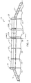
- FIGURE 1 is an illustration of the transportation system 15 of this invention erected on a site having varied terrain (the system of this invention as illustrated in FIGURE 1 is, like any bike-way system, intended to cover substantial distances, certainly in excess of 1000 meters in any given segment, and is elevated for grade control and for siting considerations, as more fully discussed hereinafter, and not merely an overpass structure for example). While the system of FIGURE 1 is shown to be elevated, elevation is but one of the improvements discussed herein and need not be utilized in every application.
- System 15 includes passage structure, or tunnel, 17 providing a pathway for rider propelled vehicles, such as bicycles. Access ways 19 and 21 provide rider entry into and egress from structure 17. Air movers, or fan units (preferably vane axial blower fans), 23 are beneficially provided to create air flow in the direction of vehicle movement (one or two way movement) through structure 17, the air flow being of a velocity sufficient to aid movement of the vehicle. While top-mounting of the fan units is shown, the fan units could be mounted at grade with appropriate ducting and allowance for duct system losses.
- Risers 25 (made of concrete, steel, wood or composite material supporting piers) support structure 17 and are of lengths selected so that the grade of the structure can be controlled without changing grade of the terrain at the site of installation. While a multi-legged riser unit 25 is shown, a pedestal type riser could also be utilized where right-of-way acquisition is even more severely limited.
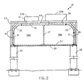
- structure 17 includes vehicle support surface 27 (poured tartan, concrete, asphalt, or the like) maintained in foundation element 29 attached to side walls 31.
- Light transmitting wall panels 33 transparent or translucent
- cover structure 35 It should be appreciated that a single unitary (for example, molded or extruded) wall could be provided in place of the multi-unit structure formed by walls 31, 33 and 35.
- Tunnel divider wall 37 (preferably selectively positionable, from left to right in the FIGURE) is maintained between cover structure 35 and surface 27 in the structure to divide structure 17 into discrete passageways 38A and 38B (though any number of passageways and/or lanes could be provided).
- the overall width of support surface 27 is selected depending on desired lane capacity as well as siting of the structure (for example, the overall structure could be wide enough to allow erection of the system over existing street right-or-ways thereby implicating no land acquisition to site the structure).
- Fan units 23A and 23B are provided with ducting 39 and 41, respectively, for supply and return air functions within each passageway to provide air flow in a direction corresponding to the intended direction of travel of vehicles through each passageway (i.e., in opposite directions).
- the fan units are appropriately supported on support structure 42 (for example, an ironwork frame support) which in turn are mounted on risers 25.
- Walls 31, 33, 37 and cover structure 35 may be constructed from common building materials such as structural steel shapes, concrete, and plastic such as Plexiglass, Lexan, or various types of recycled rigid plastic building materials (molded, blown, or heat deformation techniques may be utilized), with structure 17 preferably being assembled of discrete, transportable tunnel modules (43 in FIGURE 1) fabricated off-site.
- each of wall segments 31 and 33 and cover structure 35 include flanges 44 at their opposite ends (both ends) to facilitate interconnection of the modules, with the interconnections being appropriately sealed to preserve air flow.
- the interior of structure 17 should be aerodynamically smooth and, for purposes of the following disclosure, the smoothness of the surface is assumed to be approximately the same as commercial metal ductwork.
- proper fan capacity for fan units 23 must be determined. This is done by first determining the equivalent diameter of a circular duct by calculating the actual cross sectional area of half of structure 17 (i.e., of passageway 38A or 38B). The resulting area is then used in the formula for the area of a circle. The formula is then solved for radius and the equivalent diameter of a circular duct is thus twice the radius (the equivalent diameter referred to is for one half of the area of the interior of structure 17).
- Fan capacity calculations must be corrected for the actual density of air at the installation site. For example, standard density of air at sea level is 1.2Kg/m 3 (0.075 lbm./ft). while the density of air at 1.609km(one mile) above sea level is about 0.99Kg/m 3 (0.062 lbm./ft). Also necessary for the air calculations is velocity pressure (VP), the pressure exerted by flowing air due to the velocity. The units for velocity pressure is the Pascal (Pa) (inches of water gauge (in.w.g.).
- This empirical formula is based on standard air of 1.2kg/m 3 (0.075 lb./ft. 3 ) density flowing through clean, round, galvanized ducts with an equivalent sand grain roughness of 0.1524mm(0. 0005 ft.) (2) .
- All smooth surfaces have peaks and valleys. The mean distance between these high and low points is the absolute roughness ⁇ .
- the relative roughness ⁇ /D of the surface in a conduit is the absolute roughness divided by the effective diameter. Because of the small value for ⁇ (0.1524mm (.000005 ft). for very smooth surfaces to 3.04mm(0.01 ft.) for very rough surfaces) and the very large value for D, the relative roughness of the tunnel will be low. smoother materials are preferred and will lower the aerodynamic resistance resulting in lower energy usage and operating cost.
- the interior of structure 17 should employ as many curved walls as possible since round ducts are more effective for flowing air as compared to irregular cross sections.
- the design pressure drop through filter 45 (FIGURE 5) would be about 124.4475Pa(0.50 in. w.g.)
- the pressure drop through the filter will increase.
- automatic filters are available that advance new media into the air stream when the pressure drop exceeds a set point, resulting in a reasonably constant pressure drop.
- the design pressure drop through the heating and cooling equipment 47 would be about 497.79Pa(2.00 in. w.g.) This is a reasonable value and is obtained by using equipment with large cross sectional areas to minimize the pressure drop. Equipment with smaller cross sectional areas would cost less initially but would have higher pressure drops resulting in higher pressures required from the fans and thus higher operating cost.
- Optional fan inlet and fan discharge silencers 49 and 51 are provided to offset noise created by high horsepower vane axial fans. Specific selection of industrial grade silencers can be made after noise data for the selected fans are obtained. All major fan manufacturers provide the necessary noise data for selection of appropriate silencers.
- Total pressure is required for sizing the fan units 23.
- each fan unit 23 has two duct connections to a passageway of passage structure 17, one for supply air to the fan and one for return air to the passageway.
- FIGURE 4 shows a typical branch connection for a duct returning air from a fan to the passageway.
- the connection for a duct supplying air to a fan from the passageway would appear the same except for the directions of the air flow. Both supply and return connections should be covered with heavy wire mesh to protect riders.
- Branch connections from the fan to the passageway could be made into the vertical side walls 31 of the structure 17 or cover structure 35.
- the section of structure 17 where the connection is made would need to be constructed from a more durable material and/or reinforced or supported.
- Branch connections should preferably have a minimum angle between the passageway and branch duct (about 0.524 radians(30° )is practical). This will help to minimize pressure drop and to maintain air flow inside the passageway in the desired direction.
- the performance characteristics for a single fan unit 23 (the maximum air pressure that the fan can develop) is determined.
- fan power (bhp) density correction x quantity x static pressure/(efficiency x 6,356)
- fan units 23 dedicated to additional lanes of a passageway should be spaced equally over the distance to be covered by the lane and between the fan units of an adjacent lane (i.e., so that fan units of adjacent lanes are staggered over the distance to be covered by structure 17). This will provide even distribution of air velocity along the entire length of the multi-lane passageway, avoiding "dead spots" of reduced air velocity in areas between fan inlets and discharges. Even spacing of fans along the entire length of structure 17 helps to maintain a substantially constant overall air pressure along the entire length of the passageway.
- an intermediate access way 57 (an intermediate entryway is shown, though ways of intermediate egress may also be provided) to structure 17 enters at the smallest safe angle possible (to minimize pressure drop at the opening) into a passageway of structure 17.
- a high pressure wind curtain system could be utilized to minimize loss of system air. Since some loss of air at the site of such intermediate access ways is to be expected, an additional fan unit 23 may be required immediately adjacent to the entry or exit point.
- a special intermediate module 59 is provided having access way angle entry portion 61, and tunnel portions 63 and 65 (a y-branch type of structure). Module segments 43 and ramp modules 67 are connected to provide the desired structure at the site of installation.
- an improved transportation system, structures and methods are provided for rider propelled vehicles, the system being configured to encourage use of such vehicles as a primary mode of transportation.
Landscapes
- Ventilation (AREA)
Applications Claiming Priority (1)
| Application Number | Priority Date | Filing Date | Title |
|---|---|---|---|
| PCT/US1995/013727 WO1997015515A1 (en) | 1995-06-05 | 1995-10-23 | Transportation system for rider propelled vehicles |
Publications (3)
| Publication Number | Publication Date |
|---|---|
| EP0906234A4 EP0906234A4 (enExample) | 1999-04-07 |
| EP0906234A1 EP0906234A1 (en) | 1999-04-07 |
| EP0906234B1 true EP0906234B1 (en) | 2001-03-28 |
Family
ID=22250032
Family Applications (1)
| Application Number | Title | Priority Date | Filing Date |
|---|---|---|---|
| EP95938875A Expired - Lifetime EP0906234B1 (en) | 1995-10-23 | 1995-10-23 | Transportation system for rider propelled vehicles |
Country Status (3)
| Country | Link |
|---|---|
| EP (1) | EP0906234B1 (enExample) |
| AT (1) | ATE200065T1 (enExample) |
| DE (1) | DE69520510D1 (enExample) |
Family Cites Families (1)
| Publication number | Priority date | Publication date | Assignee | Title |
|---|---|---|---|---|
| US4078498A (en) * | 1976-08-27 | 1978-03-14 | Futer Rudolph E | Single power unit air propelled system |
-
1995
- 1995-10-23 DE DE69520510T patent/DE69520510D1/de not_active Expired - Lifetime
- 1995-10-23 EP EP95938875A patent/EP0906234B1/en not_active Expired - Lifetime
- 1995-10-23 AT AT95938875T patent/ATE200065T1/de not_active IP Right Cessation
Also Published As
| Publication number | Publication date |
|---|---|
| EP0906234A4 (enExample) | 1999-04-07 |
| EP0906234A1 (en) | 1999-04-07 |
| DE69520510D1 (de) | 2001-05-03 |
| ATE200065T1 (de) | 2001-04-15 |
Similar Documents
| Publication | Publication Date | Title |
|---|---|---|
| US7857543B2 (en) | Traffic installation | |
| US12060795B2 (en) | Roadway conduit systems and methods | |
| CN111971455B (zh) | 道路管道系统和方法 | |
| US7127999B2 (en) | Tritrack system of mass transit | |
| US20090214291A1 (en) | Set of components used to fabricate enclosed and elevated roadways that are intended for use by bicycles, other small vehicles and pedestrians; and a process, utilizing said components, for planning and designing such a roadway | |
| US11325619B2 (en) | Universal public transport and utilities distribution system | |
| US5671681A (en) | Transportation method for rider propelled vehicles | |
| CN106758579A (zh) | 立体城市的建筑与交通一体化系统 | |
| JP7323963B2 (ja) | 自律車両のための車道インフラストラクチャ | |
| US5558023A (en) | Enclosed transportation system for rider propelled vehicles with pneumatic propulsion assistance | |
| MX2008006718A (es) | Interseccion de control de trafico. | |
| EP0906234B1 (en) | Transportation system for rider propelled vehicles | |
| CA2235589C (en) | Transportation system for rider propelled vehicles | |
| KR20140014422A (ko) | 도로 및 철로에 따라 설치하는 2층 구조물을 이용한 네트워크 기반의 물류 및 교통 및 통신시스템 | |
| JP2019534965A (ja) | 都市輸送および物流システム | |
| CN219795266U (zh) | 隧道结构 | |
| CN111058365B (zh) | 一种人非在箱梁内部通行的跨江连续刚构桥梁结构 | |
| CN110497924B (zh) | 一种用于隧道的空铁轨道交通系统 | |
| MXPA98003190A (es) | Sistema de transporte para vehiculos propulsadospor el conductor | |
| Clark | General guidelines for the design of light rail transit facilities in Edmonton | |
| Brown | Electric bicycle transportation system | |
| CN202705834U (zh) | 在不同水平高度的用于车辆交通的立交桥 | |
| GB2591437A (en) | Light transport transit pack | |
| RU105628U1 (ru) | Эстакада для перемещения транспортных средств на разных уровнях | |
| NL9001234A (nl) | Personenvervoersysteem. |
Legal Events
| Date | Code | Title | Description |
|---|---|---|---|
| PUAI | Public reference made under article 153(3) epc to a published international application that has entered the european phase |
Free format text: ORIGINAL CODE: 0009012 |
|
| 17P | Request for examination filed |
Effective date: 19980515 |
|
| A4 | Supplementary search report drawn up and despatched |
Effective date: 19981126 |
|
| AK | Designated contracting states |
Kind code of ref document: A4 Designated state(s): AT BE DE DK FR GB GR IT NL SE Kind code of ref document: A1 Designated state(s): AT BE DE DK FR GB GR IT NL SE |
|
| 17Q | First examination report despatched |
Effective date: 19990422 |
|
| GRAG | Despatch of communication of intention to grant |
Free format text: ORIGINAL CODE: EPIDOS AGRA |
|
| GRAG | Despatch of communication of intention to grant |
Free format text: ORIGINAL CODE: EPIDOS AGRA |
|
| GRAG | Despatch of communication of intention to grant |
Free format text: ORIGINAL CODE: EPIDOS AGRA |
|
| GRAH | Despatch of communication of intention to grant a patent |
Free format text: ORIGINAL CODE: EPIDOS IGRA |
|
| GRAH | Despatch of communication of intention to grant a patent |
Free format text: ORIGINAL CODE: EPIDOS IGRA |
|
| GRAA | (expected) grant |
Free format text: ORIGINAL CODE: 0009210 |
|
| AK | Designated contracting states |
Kind code of ref document: B1 Designated state(s): AT BE DE DK FR GB GR IT NL SE |
|
| PG25 | Lapsed in a contracting state [announced via postgrant information from national office to epo] |
Ref country code: IT Free format text: LAPSE BECAUSE OF FAILURE TO SUBMIT A TRANSLATION OF THE DESCRIPTION OR TO PAY THE FEE WITHIN THE PRE;WARNING: LAPSES OF ITALIAN PATENTS WITH EFFECTIVE DATE BEFORE 2007 MAY HAVE OCCURRED AT ANY TIME BEFORE 2007. THE CORRECT EFFECTIVE DATE MAY BE DIFFERENT FROM THE ONE RECORDED.SCRIBED TIME-LIMIT Effective date: 20010328 Ref country code: FR Free format text: LAPSE BECAUSE OF FAILURE TO SUBMIT A TRANSLATION OF THE DESCRIPTION OR TO PAY THE FEE WITHIN THE PRESCRIBED TIME-LIMIT Effective date: 20010328 Ref country code: BE Free format text: LAPSE BECAUSE OF FAILURE TO SUBMIT A TRANSLATION OF THE DESCRIPTION OR TO PAY THE FEE WITHIN THE PRESCRIBED TIME-LIMIT Effective date: 20010328 Ref country code: AT Free format text: LAPSE BECAUSE OF FAILURE TO SUBMIT A TRANSLATION OF THE DESCRIPTION OR TO PAY THE FEE WITHIN THE PRESCRIBED TIME-LIMIT Effective date: 20010328 |
|
| REF | Corresponds to: |
Ref document number: 200065 Country of ref document: AT Date of ref document: 20010415 Kind code of ref document: T |
|
| REF | Corresponds to: |
Ref document number: 69520510 Country of ref document: DE Date of ref document: 20010503 |
|
| PG25 | Lapsed in a contracting state [announced via postgrant information from national office to epo] |
Ref country code: SE Free format text: LAPSE BECAUSE OF FAILURE TO SUBMIT A TRANSLATION OF THE DESCRIPTION OR TO PAY THE FEE WITHIN THE PRESCRIBED TIME-LIMIT Effective date: 20010628 Ref country code: DK Free format text: LAPSE BECAUSE OF FAILURE TO SUBMIT A TRANSLATION OF THE DESCRIPTION OR TO PAY THE FEE WITHIN THE PRESCRIBED TIME-LIMIT Effective date: 20010628 |
|
| PG25 | Lapsed in a contracting state [announced via postgrant information from national office to epo] |
Ref country code: GR Free format text: LAPSE BECAUSE OF FAILURE TO SUBMIT A TRANSLATION OF THE DESCRIPTION OR TO PAY THE FEE WITHIN THE PRESCRIBED TIME-LIMIT Effective date: 20010629 Ref country code: DE Free format text: LAPSE BECAUSE OF FAILURE TO SUBMIT A TRANSLATION OF THE DESCRIPTION OR TO PAY THE FEE WITHIN THE PRESCRIBED TIME-LIMIT Effective date: 20010629 |
|
| EN | Fr: translation not filed | ||
| REG | Reference to a national code |
Ref country code: GB Ref legal event code: IF02 |
|
| PLBE | No opposition filed within time limit |
Free format text: ORIGINAL CODE: 0009261 |
|
| STAA | Information on the status of an ep patent application or granted ep patent |
Free format text: STATUS: NO OPPOSITION FILED WITHIN TIME LIMIT |
|
| 26N | No opposition filed | ||
| PGFP | Annual fee paid to national office [announced via postgrant information from national office to epo] |
Ref country code: GB Payment date: 20121029 Year of fee payment: 18 |
|
| PGFP | Annual fee paid to national office [announced via postgrant information from national office to epo] |
Ref country code: NL Payment date: 20121010 Year of fee payment: 18 |
|
| REG | Reference to a national code |
Ref country code: NL Ref legal event code: V1 Effective date: 20140501 |
|
| GBPC | Gb: european patent ceased through non-payment of renewal fee |
Effective date: 20131023 |
|
| PG25 | Lapsed in a contracting state [announced via postgrant information from national office to epo] |
Ref country code: GB Free format text: LAPSE BECAUSE OF NON-PAYMENT OF DUE FEES Effective date: 20131023 |
|
| PG25 | Lapsed in a contracting state [announced via postgrant information from national office to epo] |
Ref country code: NL Free format text: LAPSE BECAUSE OF NON-PAYMENT OF DUE FEES Effective date: 20140501 |