EP0905933A2 - Method and system for mixing audio signals - Google Patents
Method and system for mixing audio signals Download PDFInfo
- Publication number
- EP0905933A2 EP0905933A2 EP97119295A EP97119295A EP0905933A2 EP 0905933 A2 EP0905933 A2 EP 0905933A2 EP 97119295 A EP97119295 A EP 97119295A EP 97119295 A EP97119295 A EP 97119295A EP 0905933 A2 EP0905933 A2 EP 0905933A2
- Authority
- EP
- European Patent Office
- Prior art keywords
- channels
- signals
- filter
- channel
- signal
- Prior art date
- Legal status (The legal status is an assumption and is not a legal conclusion. Google has not performed a legal analysis and makes no representation as to the accuracy of the status listed.)
- Withdrawn
Links
- 230000005236 sound signal Effects 0.000 title claims abstract description 15
- 238000000034 method Methods 0.000 title claims abstract description 11
- 230000003111 delayed effect Effects 0.000 claims description 7
- 238000001914 filtration Methods 0.000 claims description 5
- 238000000926 separation method Methods 0.000 abstract description 3
- 230000006870 function Effects 0.000 description 17
- 230000004044 response Effects 0.000 description 11
- 238000012546 transfer Methods 0.000 description 9
- 230000000875 corresponding effect Effects 0.000 description 6
- 238000002592 echocardiography Methods 0.000 description 6
- 238000013461 design Methods 0.000 description 4
- 230000004807 localization Effects 0.000 description 4
- 238000004091 panning Methods 0.000 description 4
- 238000010586 diagram Methods 0.000 description 3
- 239000011159 matrix material Substances 0.000 description 3
- 239000007787 solid Substances 0.000 description 3
- 241001136792 Alle Species 0.000 description 2
- 230000008901 benefit Effects 0.000 description 2
- 230000002596 correlated effect Effects 0.000 description 2
- 230000001934 delay Effects 0.000 description 2
- 230000001419 dependent effect Effects 0.000 description 2
- 230000000694 effects Effects 0.000 description 2
- 238000005516 engineering process Methods 0.000 description 2
- 238000005259 measurement Methods 0.000 description 2
- 230000007935 neutral effect Effects 0.000 description 2
- 230000008569 process Effects 0.000 description 2
- 238000012360 testing method Methods 0.000 description 2
- 238000011144 upstream manufacturing Methods 0.000 description 2
- 229930091051 Arenine Natural products 0.000 description 1
- 230000006978 adaptation Effects 0.000 description 1
- 230000002238 attenuated effect Effects 0.000 description 1
- 230000008033 biological extinction Effects 0.000 description 1
- 238000004364 calculation method Methods 0.000 description 1
- 238000006243 chemical reaction Methods 0.000 description 1
- 238000010276 construction Methods 0.000 description 1
- 230000001276 controlling effect Effects 0.000 description 1
- 238000013016 damping Methods 0.000 description 1
- 230000002349 favourable effect Effects 0.000 description 1
- 238000003384 imaging method Methods 0.000 description 1
- 238000009434 installation Methods 0.000 description 1
- 238000013507 mapping Methods 0.000 description 1
- 239000000463 material Substances 0.000 description 1
- 230000007246 mechanism Effects 0.000 description 1
- 238000010606 normalization Methods 0.000 description 1
- 238000005457 optimization Methods 0.000 description 1
- 230000008447 perception Effects 0.000 description 1
- 238000012545 processing Methods 0.000 description 1
- 230000005855 radiation Effects 0.000 description 1
- 238000011160 research Methods 0.000 description 1
- 230000000717 retained effect Effects 0.000 description 1
- 238000004088 simulation Methods 0.000 description 1
- 230000007306 turnover Effects 0.000 description 1
Images

Classifications
-
- H—ELECTRICITY
- H04—ELECTRIC COMMUNICATION TECHNIQUE
- H04S—STEREOPHONIC SYSTEMS
- H04S7/00—Indicating arrangements; Control arrangements, e.g. balance control
- H04S7/30—Control circuits for electronic adaptation of the sound field
- H04S7/302—Electronic adaptation of stereophonic sound system to listener position or orientation
-
- G—PHYSICS
- G10—MUSICAL INSTRUMENTS; ACOUSTICS
- G10L—SPEECH ANALYSIS TECHNIQUES OR SPEECH SYNTHESIS; SPEECH RECOGNITION; SPEECH OR VOICE PROCESSING TECHNIQUES; SPEECH OR AUDIO CODING OR DECODING
- G10L19/00—Speech or audio signals analysis-synthesis techniques for redundancy reduction, e.g. in vocoders; Coding or decoding of speech or audio signals, using source filter models or psychoacoustic analysis
- G10L19/008—Multichannel audio signal coding or decoding using interchannel correlation to reduce redundancy, e.g. joint-stereo, intensity-coding or matrixing
-
- H—ELECTRICITY
- H04—ELECTRIC COMMUNICATION TECHNIQUE
- H04S—STEREOPHONIC SYSTEMS
- H04S3/00—Systems employing more than two channels, e.g. quadraphonic
- H04S3/02—Systems employing more than two channels, e.g. quadraphonic of the matrix type, i.e. in which input signals are combined algebraically, e.g. after having been phase shifted with respect to each other
Definitions
- the invention relates to a method and an apparatus for mixing Sound signals.
- Devices of this type are commonly referred to as mixing consoles and are used for the parallel processing of several audio signals.
- the stereo technology will be Surround "playback processes are being replaced.
- surround sound consoles only contain an extension matrix extended to several output channels.
- Panpots (panorama potentiometers) in such a way that the sound source is positioned acoustically in the room. If the listener experiences the illusion that the sound is created in the room outside the loudspeakers, this is known as Phantom Sound Sources ".
- the B-format decoder has the task of controlling the loudspeakers in such a way that the sound field is optimally reconstructed at one point in the room, that of the listener.
- the following disadvantages related to the problem given here are: It turns out that the localization sharpness that can be achieved is too low. Adjacent and opposite speakers emit the same signal except for a small difference in level. To achieve discrete effects ", however, a high channel separation is required. For example, when mixing a film, a noise should come exactly from a certain direction.
- the invention as set out in the claims thus solves the Task to create a method and an apparatus with which possible the most natural reproduction of the Sound signals through a plurality of speakers are made possible if one is used there is a different number of sound sources.
- the device for mixing sound signals from input channels E1 to EN on output channels A1 to AM has intermediate channels Z1 to ZK that on the one hand via a totalizer S and a multiplier M with 1 to n Subchannels of each input channel and on the other hand with a decoder D are connected, which has A1 to AM output channels.
- a decoder D One is in decoder D.
- Intermediate channel into a number corresponding to the number of output channels Filter channels divided with filters and each filter channel is with a totalizer connected to a filter channel of every other intermediate channel.
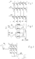
- Fig. 1 shows a known device already mentioned in the introduction Channels K1, K2 to KN for input signals, for example from a microphone and channels A1, A2, A3, A4, A5 etc. for output signals for example for one corresponding number of speakers.
- the channels K1 to KN are not over here shown multipliers for factors a11 to aN5 and totalizer S with the channels or sum rails A1, A2, A3, A4, A5, etc. connected.
- this device represents a so-called.
- Sum matrix circuit in which Input signals weighted directly by the multipliers and the summing rails A1, A2, A3, A4, A5 can be fed. So there is a signal for each speaker available, which is composed of several input signals, whereby the Share of an input signal in the output signal of the summing rail A1, A2 etc. is measured by a multiplication factor a11 to aN5.
- FIG. 2 shows a further known device which has already been mentioned in the introduction where only one of many possible input channels E1 is shown here. This is divided into further channels e11, e12 etc. into which a delay circuit V1, V2 etc. is used. Outputs of each of these delay circuits V1, V2 each lead to a circuit HRTF1 - 4 for realizing a Head transfer function. Outputs of these HRTF circuits are in turn over Totalizer S on two sum buses B1, B2 for two-channel stereo playback connected. This corresponds to the binaural mixer mentioned at the beginning according to Richter and Persterer.
- Fig. 3 shows a third known device according to D. McGrath in the, as well mentioned at the beginning, an input signal from a channel E is divided several times and into Delay circuits Ve are delayed, as is known with factors w1 to y2 multiplied or weakened and with summers S on three channels Kw, Kx and Ky arrive and there form the already mentioned signals w, x and y.
- a decoder BD converts these signals w, x and y into input signals for e.g. five speakers around.
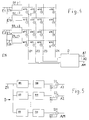
- Fig. 4 shows schematically the device according to the invention with two Input channels E1, E2, which can be expanded up to EN input channels.
- Each input channel E1, E2 etc. is again divided into several channels E1a, E1b, E2a, E2b, etc., whereby the division into n channels can also take place here.
- a delay circuit D1, D2, D3, D4, etc. is used, which can be controlled via control inputs 1, 2, 3, 4.
- Intermediate channels Z1 to ZK are via summer S with each input channel E1a, E1b, E2a, E2b to ENn connected, with each summer still a multiplier, not shown here is connected upstream (see also Fig. 6). All intermediate channels Z1 to ZK open a decoder D, the outputs of which form output channels A1, A2 to AM.
- FIG. 5 shows a diagram for the structure of the decoder D according to FIG. 4.
- This has the same number of inputs as intermediate channels Z1 to ZK.
- Every intermediate channel is again divided into as many filter channels as there should be outputs. Therefore are these filter channels with the same reference numerals A1, A2, AM as that Output channels in Fig. 4 provided.
- A1, A2, AM as that Output channels in Fig. 4 provided.
- each filter channel or output channel A1 to AM has an IIR filter and a FIR filter in the decoder D and is in series switched.
- a summer S1, S2, SM provided in each filter or output channel A1 to AM is before the output of the Decoder D a summer S1, S2, SM provided.
- the summers S point as many inputs as there are intermediate channels Z1 to ZK.
- FIG. 6 shows a summer S, which here is connected to the intermediate channel Z1, for example is connected, with an upstream multiplier M, which has an input for Factors a11, a12, etc., as known from FIG. 4, and that to one Input channel, here E1a, is connected.
- FIG. 7 shows the most important standardized surround format at the moment. It consists of a receiver 15 arranged directly in front of a circle 15 Center speaker "20 (installation angle 0 °), two stereo speakers 21, 22 at the same distance from the listener at an angle of +/- 30 °, as well as two rear surround speakers 23, 24 at an angle of +/- (110..130)
- the front loudspeakers 20, 21, 22 serve to transmit the sound events so that a stage is created, while the rear systems 23, 24 predominantly emit diffuse room echoes.
- Fig. 8 shows a head of a receiver 25, shown here as a circle and one out a beam 26 incident at an angle ⁇ .
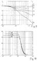
- Fig. 10 shows a frequency response for the transit time for a signal from three fixed Spatial directions with 15 °, 22.5 ° and 30 ° angle of incidence, along the abscissa Values for frequencies from 10 - 100000 Hertz and along the ordinate values for Time delays are plotted.
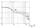
- 11 shows resulting amplitude frequency responses of the indirect component for a Signal from three spatial directions, with values for frequencies along the abscissa and values for the damping of the amplitudes in dB are plotted along the ordinate are. This for signals from the spatial directions 15 °, 22.5 ° and 30 °.
- the mode of operation of the invention is as follows:
- a decoder D converts the resulting sum signal Z1 to ZK into the desired speaker format.
- the front resolution is 15 °.
- the weighting factors a11 .... b2K are determined as follows: According to the assignment to a certain spatial direction, a maximum of two of the K factors differ from zero. If the signal should come from an angle ⁇ (Fig.
- the filters are designed as head-related filters, the shading of the head being simulated relative to a reference direction (eg 0 ° or 30 °). This takes into account the rule explained at the outset that the loudspeakers should emit correlated signals corresponding to nature. Normalized head transfer functions are therefore implemented in relation to this direction. The typical frequency responses shown in FIG. 9 are obtained.
- the side facing the head is shown ( direct ") and the opposite side ( indirectly "). With increasing shading, the attenuation of high frequencies increases.
- the filters are based on a simple head model (sphere). The advantage of this choice is that the perceived tone color remains largely neutral regardless of the individual listener and the exact listening position.
- a recursive filter models the interaural Runtime differences up to a certain upper limit frequency (see Fig. 10).
- a linear-phase FIR filter models the Differences in intensity, such as. B. shown in Fig. 9.
Landscapes
- Physics & Mathematics (AREA)
- Engineering & Computer Science (AREA)
- Acoustics & Sound (AREA)
- Signal Processing (AREA)
- Stereophonic System (AREA)
- Circuit For Audible Band Transducer (AREA)
Abstract
Description
Die Erfindung betrifft ein Verfahren und eine Vorrichtung zum Mischen von Tonsignalen.The invention relates to a method and an apparatus for mixing Sound signals.
Vorrichtungen dieser Art werden gemeinhin als Mischpulte bezeichnet und dienen
der parallelen Verarbeitung von mehreren Tonsignalen. Im Zuge der Einführung
neuer Medien (HDTV, Heimkino, DVD) wird die Stereotechnik in Zukunft durch
mehrkanalige, sog. ![]()
![]()
Psychoakustische Forschungen und Erfahrungen der letzten Jahre haben gezeigt,
dass mit den oben beschriebenen, hier kurz als
Eine der ersten digitalen Realisierungen wurde von F. Richter und A. Persterer unter
dem Titel
D. S. McGrath und A. Reilly haben unter dem Titel
Es zeigt sich, dass die erzielbare Lokalisationsschärfe zu gering ist. Benachbarte
und gegenüberliegende Lautsprecher strahlen bis auf einen kleinen
Pegelunterschied das gleiche Signal ab. Zur Erzielung
It turns out that the localization sharpness that can be achieved is too low. Adjacent and opposite speakers emit the same signal except for a small difference in level. To achieve
Die Erfindung, wie sie in den Patentansprüchen wiedergegeben ist, löst somit die Aufgabe, ein Verfahren und eine Vorrichtung zu schaffen, mit denen bei möglichst geringem technischem Aufwand eine möglichst natürliche Wiedergabe von Tonsignalen über eine Mehrzahl Lautsprecher ermöglicht wird, wenn eine dazu abweichende Zahl Schallquellen vorliegt.The invention as set out in the claims thus solves the Task to create a method and an apparatus with which possible the most natural reproduction of the Sound signals through a plurality of speakers are made possible if one is used there is a different number of sound sources.
Dies wird dadurch erreicht, dass zum Mischen von 1 bis N Tonsignalen zu 1 bis M Ausgangssignalen, das Tonsignal aus jedem Eingangskanal aufgeteilt und wahlweise verzögert wird, dass jedes aufgeteilte und wahlweise verzögerte Ton- oder Eingangssignal wahlweise gewichtet und mit entsprechenden weiteren Eingangssignalen aus anderen Eingangskanälen zu je einem Zwischensignal 1 bis K addiert wird und dass jedes Zwischensignal in Ausgangskanäle 1 bis M aufgeteilt, gefiltert und anschliessend mit den anderen Zwischensignalen summiert wird. Summierte Zwischensignale ergeben zusammen ein Ausgangssignal für einen Lautsprecher.This is achieved by mixing 1 to N audio signals to 1 to M Output signals, the sound signal split from each input channel and optionally delayed that each split and optionally delayed sound or Input signal optionally weighted and with corresponding others Input signals from other input channels, each with an intermediate signal 1 to K is added and that each intermediate signal is divided into output channels 1 to M, filtered and then summed with the other intermediate signals. Summed intermediate signals together result in an output signal for one Speaker.
Die Vorrichtung zum Mischen von Tonsignalen aus Eingangskanälen E1 bis EN auf Ausgangskanäle A1 bis AM weist Zwischenkanäle Z1 bis ZK auf, die einerseits über je einen Summierer S und je einen Multiplizierer M mit 1 bis n Teilkanälen jedes Eingangskanales und andererseits mit einem Dekodierer D verbunden sind, der A1 bis AM Ausgangskanäle aufweist. Im Dekodierer D ist jeder Zwischenkanal in eine, der Zahl der Ausgangskanäle entsprechende Anzahl Filterkanäle mit Filtern aufgeteilt und jeder Filterkanal ist über einen Summierer mit einem Filterkanal jedes anderen Zwischenkanales verbunden. The device for mixing sound signals from input channels E1 to EN on output channels A1 to AM has intermediate channels Z1 to ZK that on the one hand via a totalizer S and a multiplier M with 1 to n Subchannels of each input channel and on the other hand with a decoder D are connected, which has A1 to AM output channels. Everyone is in decoder D. Intermediate channel into a number corresponding to the number of output channels Filter channels divided with filters and each filter channel is with a totalizer connected to a filter channel of every other intermediate channel.
Die dadurch erreichten Vorteile sind insbesondere darin zu sehen, dass die eingangs definierte Aufgabenstellung in allen Punkten gelöst ist. Insbesondere ist der Aufwand minimal, weil die rechenintensiven Filter nur einmal im System, am Ausgang, benötigt werden.Das vorgeschlagene Schallfeldformat eignet sich hervorragend für die Archivierung von Musikmaterial, da alle gängigen Mehrkanalformate durch Wahl des passenden Dekoders erzeugt werden können. Ebenso können bewegte Quellen in einfacher Weise simuliert werden, da keine Umschaltung von Filtern erforderlich ist.The advantages achieved by this can be seen in particular in that the task defined in the beginning has been solved in all points. In particular is the effort is minimal, because the computationally intensive filters only once in the system Output, the proposed sound field format is suitable excellent for archiving music material, since all common Multi-channel formats can be generated by choosing the appropriate decoder. Moving sources can also be simulated in a simple manner, since none Switching filters is required.
Im folgenden wird die Erfindung anhand von einen Ausführungsweg darstellenden
Figuren näher erläutert. Es zeigen:
Fig. 1 zeigt eine bekannte und in der Einleitung bereits erwähnte Vorrichtung mit Kanälen K1, K2 bis KN für Eingangssignale beispielsweise aus einem Mikrophon und Kanälen A1, A2, A3, A4, A5 usw. für Ausgangssignale beispielsweise für eine entsprechende Anzahl Lautsprecher. Die Kanäle K1 bis KN sind über hier nicht gezeigte Multiplikatoren für Faktoren a11 bis aN5 und Summierer S mit den Kanälen oder Summenschienen A1, A2, A3, A4, A5, usw. verbunden. Wie bereits eingangs beschrieben stellt diese Vorrichtung eine sog. Summenmatrix-Schaltung dar, bei der Eingangssignale direkt durch die Multiplizierer gewichtet und den Summenschienen A1, A2, A3, A4, A5 zugeleitet werden. Damit ist für jeden Lautsprecher ein Signal verfügbar, das aus mehreren Eingangssignalen zusammengesetzt ist, wobei der Anteil eines Eingangssignales im Ausgangssignal der Summenschiene A1, A2 usw. durch einen Multiplikationsfaktor a11 bis aN5 bemessen wird.Fig. 1 shows a known device already mentioned in the introduction Channels K1, K2 to KN for input signals, for example from a microphone and channels A1, A2, A3, A4, A5 etc. for output signals for example for one corresponding number of speakers. The channels K1 to KN are not over here shown multipliers for factors a11 to aN5 and totalizer S with the channels or sum rails A1, A2, A3, A4, A5, etc. connected. As already mentioned described this device represents a so-called. Sum matrix circuit in which Input signals weighted directly by the multipliers and the summing rails A1, A2, A3, A4, A5 can be fed. So there is a signal for each speaker available, which is composed of several input signals, whereby the Share of an input signal in the output signal of the summing rail A1, A2 etc. is measured by a multiplication factor a11 to aN5.
Fig. 2 zeigt eine weitere bekannte und in der Einleitung bereits erwähnte Vorrichtung bei der hier nur einer von vielen möglichen Eingangskanälen E1 gezeigt ist. Dieser ist aufgeteilt in weitere Kanäle e11, e12 usw. in die eine Verzögerungsschaltung V1, V2 usw. eingesetzt ist. Ausgänge jeder dieser Verzögerungsschaltungen V1, V2 münden in je eine Schaltung HRTF1 - 4 zur Realisierung einer Kopfübertragungsfunktion. Ausgänge dieser HRTF-Schaltungen wiederum sind über Summierer S an zwei Summenbusse B1, B2 für zweikanal Stereowiedergabe angeschlossen. Dies entspricht dem eingangs erwähnten binauralen Mischpult gemäss Richter und Persterer.2 shows a further known device which has already been mentioned in the introduction where only one of many possible input channels E1 is shown here. This is divided into further channels e11, e12 etc. into which a delay circuit V1, V2 etc. is used. Outputs of each of these delay circuits V1, V2 each lead to a circuit HRTF1 - 4 for realizing a Head transfer function. Outputs of these HRTF circuits are in turn over Totalizer S on two sum buses B1, B2 for two-channel stereo playback connected. This corresponds to the binaural mixer mentioned at the beginning according to Richter and Persterer.
Fig. 3 zeigt eine dritte bekannte Vorrichtung nach D. McGrath bei der, wie ebenfalls eingangs erwähnt, ein Eingangssignal aus einem Kanal E mehrfach aufgeteilt und in Verzögerungsschaltungen Ve verzögert, bekannterweise mit Faktoren w1 bis y2 multipliziert oder abgeschwächt und mit Summierern S auf drei Kanäle Kw, Kx und Ky gelangen und dort die bereits erwähnten Signale w, x und y bilden. Ein Dekoder BD wandelt diese Signale w, x und y zu Eingangssignalen für z.B. fünf Lautsprecher um.Fig. 3 shows a third known device according to D. McGrath in the, as well mentioned at the beginning, an input signal from a channel E is divided several times and into Delay circuits Ve are delayed, as is known with factors w1 to y2 multiplied or weakened and with summers S on three channels Kw, Kx and Ky arrive and there form the already mentioned signals w, x and y. A decoder BD converts these signals w, x and y into input signals for e.g. five speakers around.
Fig. 4 zeigt schematisch die erfindungsgemässe Vorrichtung mit zwei Eingangskanälen E1, E2, die aber bis zu EN Eingangskanälen erweitert sein kann. Jeder Eingangskanal E1, E2 usw. ist wieder aufgeteilt in mehrere Kanäle E1a, E1b, E2a, E2b, usw. wobei auch hier die Aufteilung in n Kanäle erfolgen kann. In jeden dieser Kanäle ist eine Verzögerungsschaltung D1, D2, D3, D4 usw. eingesetzt, die über Steuereingänge 1, 2, 3, 4 ansteuerbar sind. Zwischenkanäle Z1 bis ZK sind über Summierer S mit jedem Eingangskanal E1a, E1b, E2a, E2b bis ENn verbunden, wobei jedem Summierer noch ein hier nicht gezeigter Multiplizierer vorgeschaltet ist (siehe auch Fig. 6). Alle Zwischenkanäle Z1 bis ZK münden in einen Dekodierer D, dessen Ausgänge Ausgangskanäle A1, A2 bis AM bilden.Fig. 4 shows schematically the device according to the invention with two Input channels E1, E2, which can be expanded up to EN input channels. Each input channel E1, E2 etc. is again divided into several channels E1a, E1b, E2a, E2b, etc., whereby the division into n channels can also take place here. In everyone of these channels, a delay circuit D1, D2, D3, D4, etc. is used, which can be controlled via control inputs 1, 2, 3, 4. Intermediate channels Z1 to ZK are via summer S with each input channel E1a, E1b, E2a, E2b to ENn connected, with each summer still a multiplier, not shown here is connected upstream (see also Fig. 6). All intermediate channels Z1 to ZK open a decoder D, the outputs of which form output channels A1, A2 to AM.
Fig. 5 zeigt ein Schema für den Aufbau des Dekoders D gemäss Fig. 4. Dieser weist die gleiche Anzahl Eingänge wie Zwischenkanäle Z1 bis ZK auf. Hier ist lediglich ein einziger Eingang oder Zwischenkanal Z1 dargestellt. Jeder Zwischenkanal ist wiederum in soviele Filterkanäle aufgeteilt, wie es Ausgänge geben soll. Deshalb sind diese Filterkanäle mit denselben Bezugszeichen A1, A2, AM wie die Ausgangskanäle in Fig. 4 versehen. In jedem Filterkanal oder Ausgangskanal A1 bis AM ist im Dekoder D je ein IIR-Filter und ein FIR-Filter eingesetzt und in Serie geschaltet. In jedem Filter- oder Ausgangskanal A1 bis AM ist vor dem Ausgang des Dekoders D ein Summierer S1, S2, SM vorgesehen. Die Summierer S weisen jeweils soviele Eingänge auf, wie es Zwischenkanäle Z1 bis ZK gibt.FIG. 5 shows a diagram for the structure of the decoder D according to FIG. 4. This has the same number of inputs as intermediate channels Z1 to ZK. Here is just one only input or intermediate channel Z1 shown. Every intermediate channel is again divided into as many filter channels as there should be outputs. Therefore are these filter channels with the same reference numerals A1, A2, AM as that Output channels in Fig. 4 provided. In each filter channel or output channel A1 to AM has an IIR filter and a FIR filter in the decoder D and is in series switched. In each filter or output channel A1 to AM is before the output of the Decoder D a summer S1, S2, SM provided. The summers S point as many inputs as there are intermediate channels Z1 to ZK.
Fig. 6 zeigt einen Summierer S, der hier beispielsweise an den Zwischenkanal Z1 angeschlossen ist, mit vorgeschaltetem Multiplizierer M, der einen Eingang für Faktoren a11, a12, usw., wie aus der Fig. 4 bekannt, aufweist und der an einen Eingangskanal, hier E1a, angeschlossen ist.6 shows a summer S, which here is connected to the intermediate channel Z1, for example is connected, with an upstream multiplier M, which has an input for Factors a11, a12, etc., as known from FIG. 4, and that to one Input channel, here E1a, is connected.
Fig. 7 zeigt das zur Zeit wichtigste standardisierte Surround-Format. Es besteht aus
einem, direkt vor einem als Kreis dargestellten Hörer 15 angeordneten
Vorne wird also eine wesentlich präzisere Abbildungsfähigkeit gefordert.
Dieser Tatsache kann bei der Auswahl der Raumrichtungen Rechnung getragen
werden, indem man die Auflösung entsprechend unterschiedlich wählt. Sehr gute
Ergebnisse erzielt man bereits mit K = 9 Kanälen, mit den folgenden
Intervallgrenzen:
Fig. 8 zeigt einen Kopf eines Hörers 25, hier als Kreis dargestellt und einen, aus einer Quelle in einem Winkel α einfallenden Strahl 26.Fig. 8 shows a head of a receiver 25, shown here as a circle and one out a beam 26 incident at an angle α.
Fig. 9 zeigt resultierende Amplitudenfrequenzgänge eines auf 30° normierten
kopfbezogenen Filterpaares für unterschiedliche Schalleinfallswinkel. Je nach
Einfallswinkel des Schalls, der auf einen Hörer (Kopf) trifft, ergeben sich
unterschiedliche Frequenzgänge 10 bis 14 für die Amplituden eines Signals, das von
einem Lautsprecher abgestrahlt wird. Der Lautsprecher, der sich in der gleichen
Halbebene wie das einfallende Schallsignal befindet, strahlt
Fig. 10 zeigt einen Frequenzgang für die Laufzeit für ein Signal aus drei festgelegten Raumrichtungen mit 15°, 22.5° und 30° Einfallswinkel, wobei längs der Abszisse Werte für Frequenzen von 10 - 100000 Hertz und längs der Ordinate Werte für Zeitverzögerungen aufgetragen sind.Fig. 10 shows a frequency response for the transit time for a signal from three fixed Spatial directions with 15 °, 22.5 ° and 30 ° angle of incidence, along the abscissa Values for frequencies from 10 - 100000 Hertz and along the ordinate values for Time delays are plotted.
Fig. 11 zeigt resultierende Amplitudenfrequenzgänge des Indirektanteils für ein Signal aus drei Raumrichtungen, wobei längs der Abszisse Werte für Frequenzen und längs der Ordinate Werte für die Dämpfung der Amplituden in dB aufgetragen sind. Dies für Signale aus den Raumrichtungen 15°, 22.5° und 30°.11 shows resulting amplitude frequency responses of the indirect component for a Signal from three spatial directions, with values for frequencies along the abscissa and values for the damping of the amplitudes in dB are plotted along the ordinate are. This for signals from the spatial directions 15 °, 22.5 ° and 30 °.
Die Wirkungsweise der Erfindung ist dabei wie folgt:The mode of operation of the invention is as follows:
Sollen beispielsweise zwei Eingangssignale über die Vorrichtung gemäss Fig. 4 in M = 5 Ausgangssignale für fünf Lautsprecher umgewandelt werden, so werden die beiden Eingangssignale E1 und E2 zunächst beispielsweise in je zwei Eingangssignale E1a, E1b und E2a, E2b aufgeteilt. Die Eingangssignale E1a und E2a sollen nicht verzögert werden, weil sie zur direkten, nicht reflektierten Abstrahlung an den Hörer vorgesehen sind. Sie erhalten deshalb eine Verzögerung mit dem Betrag Null. Die Eingangssignale E1b und E2b sollen reflektierte und deshalb eine grössere Laufzeit aufweisende Signale bilden oder simulieren. Deshalb werden sie in den Verzögerungsschaltungen D2 und D4 mit einer bestimmten Verzögerung versehen. Entsprechend dem in Fig. 7 gezeigten Format, sind beispielsweise neun Zwischenkanäle Z1 bis Z9 vorgesehen. Der Bediener der Vorrichtung, also des beispielsweise so aufgebauten Mischpultes legt nun einerseits die vorgenannte Verzögerung sowie die Faktoren a11 bis b2K fest, wobei er sich durch weiter unten wiedergegebene Gesichtspunkte leiten lässt.For example, if two input signals are to be sent via the device according to FIG. 4 in M = 5 output signals are converted for five speakers, so the two input signals E1 and E2 initially, for example, in two each Input signals E1a, E1b and E2a, E2b split. The input signals E1a and E2a should not be delayed because they are direct, not reflected Radiation to the listener are provided. You therefore get a delay with the amount zero. The input signals E1b and E2b should be reflected and therefore form or simulate signals with a longer transit time. Therefore they are in the delay circuits D2 and D4 with a certain Delay. According to the format shown in FIG for example, nine intermediate channels Z1 to Z9 are provided. The operator of the The device, that is to say the mixer thus constructed, now lays on the one hand the aforementioned delay as well as the factors a11 to b2K can be guided by aspects given below.
Dann stehen am Dekodierer D (siehe Beisp. Fig. 7) neun Zwischensignale Z1 bis ZK an, von denen jedes wieder in M = 5 Signale A1 - AM aufgeteilt und zuerst im IIR und dann im FIR-Filter gefiltert werden. Anschliessend werden die aufgeteilten Signale A1 bis AM mit dem entsprechenden Signal A1 bis AM aus den anderen Zwischenkanälen Z2 bis ZK summiert, was in unserem Beispiel aus zunächst 5 X 9 = 45 Signalen wieder fünf Ausgangssignale A1 bis AM ergibt.Then there are nine intermediate signals Z1 to ZK at the decoder D (see example FIG. 7) , each of which is again divided into M = 5 signals A1 - AM and first in the IIR and then filtered in the FIR filter. Then the divided Signals A1 to AM with the corresponding signal A1 to AM from the others Intermediate channels Z2 to ZK add up, which in our example is initially 5 X 9 = 45 signals again results in five output signals A1 to AM.
Mit anderen Worten werden von N Eingangskanälen mit Verzögerungsgliedern
Echos erzeugt und die direkten Signalanteile (im allgemeinen ist Delay 1 = 0) werden
gewichtet mit den Faktoren a11, b11, ... auf K Summenschienen aufgeschaltet,
welche unmittelbar bestimmten, beliebig wählbaren Raumrichtungen zugeordnet
sind. Ebenso werden Echos mit Faktoren b11 .... b1K usw. auf die Summenschienen
aufgeschaltet. Ein Dekoder D setzt das entstandene Summensignal Z1 bis ZK in das
jeweils gewünschte Lautsprecherformat um. Die Auflösung vorn beträgt dabei 15°.
Die Gewichtsfaktoren a11....b2K werden wie folgt bestimmt:
Gemäss der Zuordnung zu einer bestimmten Raumrichtung sind maximal zwei der K
Faktoren von Null verschieden. Soll das Signal aus einem Winkel ϕ (Fig. 7) kommen,
der nicht exakt in der Mitte der definierten Winkelintervalle liegt, so wird eine
Gewichtung gemäss den Funktionen
a1 = 0, a2 = 0, a3 = 0, a4 = 0, a5 = 0,
a 1 = 0, a 2 = 0, a 3 = 0, a 4 = 0, a 5 = 0,
Es ist insbesondere darauf hinzuweisen, dass der Dekoder D (Fig. 5) nur einmal im
System (am Summenausgang) benötigt wird. Alle i Summensignale (
Wesentlicher Bestandteil der Erfindung ist, dass die Filter, wie in Fig. 5 dargestellt, aufgeteilt werden. Ein rekursives Filter (IIR-Allpass) modelliert die interauralen Laufzeitunterschiede bis zu einer bestimmten oberen Grenzfrequenz (siehe Fig. 10). Ein linearphasiges FIR-Filter modelliert unabhängig davon die Intensitätsunterschiede, wie z. B. in Fig. 9 dargestellt. Mit dieser Anordnung vermeidet man unerwünschte Kammfilter-effekte, die entstehen, wenn man zwei unterschiedlich verzögerte Signale addiert. Man würde dann oberhalb einer bestimmten Frequenzgrenze Auslöschungen an den Stellen bekommen, wo die Phasendifferenz 180° erreicht. Daher wird hier keine konstante, sondern eine frequenzabhängige Laufzeit realisiert, die bei hohen Frequenzen gegen Null strebt. Ordnet man einem Signal einen Raumwinkel zu, der genau an der Grenze zwischen zwei Intervallen liegt, wie im Beispiel oben, so erhält man die in Fig. 10 bzw. Fig. 11 dargestellten Frequenzgänge. Man erkennt, dass trotz der zugrundeliegenden, relativ geringen Kanalanzahl von 9 eine sehr gute Interpolation erzielt wird. Dies bedeutet, dass eine Schallquelle quasi kontinuierlich im Raum bewegt werden kann, trotz der niedrigen Anzahl fest implementierter Kopfübertragungsfunktionen.An essential part of the invention is that the filters, as shown in Fig. 5, be divided. A recursive filter (IIR allpass) models the interaural Runtime differences up to a certain upper limit frequency (see Fig. 10). Independently of this, a linear-phase FIR filter models the Differences in intensity, such as. B. shown in Fig. 9. With this arrangement you avoid unwanted comb filter effects that arise when you have two different delayed signals added. You would then be above one certain frequency limit get extinctions where the Phase difference reached 180 °. Therefore, here is not a constant, but one frequency-dependent runtime realized, which strives towards zero at high frequencies. If you assign a solid angle to a signal that is exactly on the boundary between If there are two intervals, as in the example above, one obtains those in FIGS. 10 and 11 shown frequency responses. You can see that despite the underlying, relatively small number of channels of 9 a very good interpolation is achieved. This means that a sound source can be moved almost continuously in the room, despite the low number of permanently implemented head transfer functions.
Die Auslegung der Filter im Dekoder hat vorzugsweise folgendermassen zu
geschehen:
Der Entwurf soll am gegebenen Beispiel mit 9 Schallfeldsignalen und 5
Lautsprechern erklärt werden (siehe Fig. 7). Mit Ausnahme der Kanäle 1 und 9, die
hier direkt, ohne Filter zu durchlaufen, mit den entsprechenden rückwärtigen
Lautsprechern verbunden werden, sind die in Fig. 5 gezeigten Filter von
Kopfübertragungsfunktionen abgeleitet, welche gemäss Fig. 8 definiert sind. Die
Filterfunktion H(D, a) bezeichnet die an dem der Schallquelle zugewandten Ohr
auftretende Übertragungsfunktion, H(I, a) die der gegenüberliegenden Seite. Die
Funktionen sind von der Einfallsrichtung α abhängig, die gezählt wird beginnend
vom rechten Ohr gegen den Uhrzeigersinn. Solche Funktionen erhält man z. B.
durch Messungen an Versuchspersonen, Kunstköpfen oder durch Berechnung an
einfachen Kopfmodellen wie von D. H. Cooper in:
The design is to be explained using the given example with 9 sound field signals and 5 loudspeakers (see FIG. 7). With the exception of channels 1 and 9, which here are connected directly to the corresponding rear speakers without going through filters, the filters shown in FIG. 5 are derived from head transfer functions, which are defined according to FIG. 8. The filter function H (D, a) denotes the transfer function occurring at the ear facing the sound source, H (I, a) that on the opposite side. The functions depend on the direction of incidence α, which is counted starting from the right ear counterclockwise. Such functions are obtained e.g. B. by measurements on test subjects, artificial heads or by calculation on simple head models such as from DH Cooper in:
Claims (8)
Applications Claiming Priority (3)
| Application Number | Priority Date | Filing Date | Title |
|---|---|---|---|
| CH224897 | 1997-09-24 | ||
| CH2248/97 | 1997-09-24 | ||
| CH224897 | 1997-09-24 |
Publications (2)
| Publication Number | Publication Date |
|---|---|
| EP0905933A2 true EP0905933A2 (en) | 1999-03-31 |
| EP0905933A3 EP0905933A3 (en) | 2004-03-24 |
Family
ID=4229340
Family Applications (1)
| Application Number | Title | Priority Date | Filing Date |
|---|---|---|---|
| EP97119295A Withdrawn EP0905933A3 (en) | 1997-09-24 | 1997-11-05 | Method and system for mixing audio signals |
Country Status (2)
| Country | Link |
|---|---|
| US (1) | US6363155B1 (en) |
| EP (1) | EP0905933A3 (en) |
Cited By (1)
| Publication number | Priority date | Publication date | Assignee | Title |
|---|---|---|---|---|
| DE102010005067A1 (en) * | 2010-01-15 | 2011-07-21 | Dr. Ing. h.c. F. Porsche Aktiengesellschaft, 70435 | Device for noise transmission in motor car, has transfer lines actively connected with valve arrangement such that sound emission of lines into passenger inner space is adjustable by displacement of arrangement |
Families Citing this family (43)
| Publication number | Priority date | Publication date | Assignee | Title |
|---|---|---|---|---|
| WO1998058523A1 (en) * | 1997-06-17 | 1998-12-23 | British Telecommunications Public Limited Company | Reproduction of spatialised audio |
| US6507658B1 (en) * | 1999-01-27 | 2003-01-14 | Kind Of Loud Technologies, Llc | Surround sound panner |
| US6977653B1 (en) * | 2000-03-08 | 2005-12-20 | Tektronix, Inc. | Surround sound display |
| AUPQ942400A0 (en) * | 2000-08-15 | 2000-09-07 | Lake Technology Limited | Cinema audio processing system |
| US6804565B2 (en) * | 2001-05-07 | 2004-10-12 | Harman International Industries, Incorporated | Data-driven software architecture for digital sound processing and equalization |
| JP4409177B2 (en) | 2003-01-07 | 2010-02-03 | ヤマハ株式会社 | Data processing apparatus, data processing method and program |
| EP1590266B8 (en) * | 2003-02-05 | 2011-01-26 | Martin John Tedham | Dispenser for products enclosed in a blister pack |
| JP2006203850A (en) * | 2004-12-24 | 2006-08-03 | Matsushita Electric Ind Co Ltd | Sound image locating device |
| US7698009B2 (en) * | 2005-10-27 | 2010-04-13 | Avid Technology, Inc. | Control surface with a touchscreen for editing surround sound |
| KR101368859B1 (en) * | 2006-12-27 | 2014-02-27 | 삼성전자주식회사 | Method and apparatus for reproducing a virtual sound of two channels based on individual auditory characteristic |
| US20080175400A1 (en) * | 2007-01-24 | 2008-07-24 | Napoletano Nathaniel M | Comm-check surrogate for communications networks |
| KR101418023B1 (en) * | 2008-03-14 | 2014-07-09 | 삼성전자주식회사 | Apparatus and method for automatic gain control using phase information |
| US8971542B2 (en) * | 2009-06-12 | 2015-03-03 | Conexant Systems, Inc. | Systems and methods for speaker bar sound enhancement |
| EP2600343A1 (en) * | 2011-12-02 | 2013-06-05 | Fraunhofer-Gesellschaft zur Förderung der angewandten Forschung e.V. | Apparatus and method for merging geometry - based spatial audio coding streams |
| US9084058B2 (en) | 2011-12-29 | 2015-07-14 | Sonos, Inc. | Sound field calibration using listener localization |
| US9706323B2 (en) | 2014-09-09 | 2017-07-11 | Sonos, Inc. | Playback device calibration |
| US9690539B2 (en) | 2012-06-28 | 2017-06-27 | Sonos, Inc. | Speaker calibration user interface |
| US9219460B2 (en) | 2014-03-17 | 2015-12-22 | Sonos, Inc. | Audio settings based on environment |
| US9106192B2 (en) | 2012-06-28 | 2015-08-11 | Sonos, Inc. | System and method for device playback calibration |
| US9264839B2 (en) | 2014-03-17 | 2016-02-16 | Sonos, Inc. | Playback device configuration based on proximity detection |
| US9952825B2 (en) | 2014-09-09 | 2018-04-24 | Sonos, Inc. | Audio processing algorithms |
| US9910634B2 (en) | 2014-09-09 | 2018-03-06 | Sonos, Inc. | Microphone calibration |
| US10127006B2 (en) | 2014-09-09 | 2018-11-13 | Sonos, Inc. | Facilitating calibration of an audio playback device |
| US9891881B2 (en) | 2014-09-09 | 2018-02-13 | Sonos, Inc. | Audio processing algorithm database |
| WO2016172593A1 (en) | 2015-04-24 | 2016-10-27 | Sonos, Inc. | Playback device calibration user interfaces |
| US10664224B2 (en) | 2015-04-24 | 2020-05-26 | Sonos, Inc. | Speaker calibration user interface |
| US9538305B2 (en) | 2015-07-28 | 2017-01-03 | Sonos, Inc. | Calibration error conditions |
| CN111314826B (en) | 2015-09-17 | 2021-05-14 | 搜诺思公司 | Method performed by a computing device and corresponding computer readable medium and computing device |
| US9693165B2 (en) | 2015-09-17 | 2017-06-27 | Sonos, Inc. | Validation of audio calibration using multi-dimensional motion check |
| US9743207B1 (en) | 2016-01-18 | 2017-08-22 | Sonos, Inc. | Calibration using multiple recording devices |
| US10003899B2 (en) | 2016-01-25 | 2018-06-19 | Sonos, Inc. | Calibration with particular locations |
| US11106423B2 (en) | 2016-01-25 | 2021-08-31 | Sonos, Inc. | Evaluating calibration of a playback device |
| US9860662B2 (en) | 2016-04-01 | 2018-01-02 | Sonos, Inc. | Updating playback device configuration information based on calibration data |
| US9864574B2 (en) | 2016-04-01 | 2018-01-09 | Sonos, Inc. | Playback device calibration based on representation spectral characteristics |
| US9763018B1 (en) | 2016-04-12 | 2017-09-12 | Sonos, Inc. | Calibration of audio playback devices |
| US9860670B1 (en) | 2016-07-15 | 2018-01-02 | Sonos, Inc. | Spectral correction using spatial calibration |
| US9794710B1 (en) | 2016-07-15 | 2017-10-17 | Sonos, Inc. | Spatial audio correction |
| US10372406B2 (en) | 2016-07-22 | 2019-08-06 | Sonos, Inc. | Calibration interface |
| US10459684B2 (en) | 2016-08-05 | 2019-10-29 | Sonos, Inc. | Calibration of a playback device based on an estimated frequency response |
| US10699729B1 (en) * | 2018-06-08 | 2020-06-30 | Amazon Technologies, Inc. | Phase inversion for virtual assistants and mobile music apps |
| US11206484B2 (en) | 2018-08-28 | 2021-12-21 | Sonos, Inc. | Passive speaker authentication |
| US10299061B1 (en) | 2018-08-28 | 2019-05-21 | Sonos, Inc. | Playback device calibration |
| US10734965B1 (en) | 2019-08-12 | 2020-08-04 | Sonos, Inc. | Audio calibration of a portable playback device |
Citations (3)
| Publication number | Priority date | Publication date | Assignee | Title |
|---|---|---|---|---|
| WO1993018630A1 (en) * | 1992-03-02 | 1993-09-16 | Trifield Productions Ltd. | Surround sound apparatus |
| US5555306A (en) * | 1991-04-04 | 1996-09-10 | Trifield Productions Limited | Audio signal processor providing simulated source distance control |
| WO1997030566A1 (en) * | 1996-02-16 | 1997-08-21 | Adaptive Audio Limited | Sound recording and reproduction systems |
Family Cites Families (5)
| Publication number | Priority date | Publication date | Assignee | Title |
|---|---|---|---|---|
| JPH0787337B2 (en) * | 1990-01-05 | 1995-09-20 | ヤマハ株式会社 | Acoustic signal processor |
| US5420929A (en) * | 1992-05-26 | 1995-05-30 | Ford Motor Company | Signal processor for sound image enhancement |
| US5337366A (en) * | 1992-07-07 | 1994-08-09 | Sharp Kabushiki Kaisha | Active control apparatus using adaptive digital filter |
| US5438623A (en) * | 1993-10-04 | 1995-08-01 | The United States Of America As Represented By The Administrator Of National Aeronautics And Space Administration | Multi-channel spatialization system for audio signals |
| US5742689A (en) * | 1996-01-04 | 1998-04-21 | Virtual Listening Systems, Inc. | Method and device for processing a multichannel signal for use with a headphone |
-
1997
- 1997-11-05 EP EP97119295A patent/EP0905933A3/en not_active Withdrawn
- 1997-12-22 US US08/996,203 patent/US6363155B1/en not_active Expired - Lifetime
Patent Citations (3)
| Publication number | Priority date | Publication date | Assignee | Title |
|---|---|---|---|---|
| US5555306A (en) * | 1991-04-04 | 1996-09-10 | Trifield Productions Limited | Audio signal processor providing simulated source distance control |
| WO1993018630A1 (en) * | 1992-03-02 | 1993-09-16 | Trifield Productions Ltd. | Surround sound apparatus |
| WO1997030566A1 (en) * | 1996-02-16 | 1997-08-21 | Adaptive Audio Limited | Sound recording and reproduction systems |
Non-Patent Citations (2)
| Title |
|---|
| EUROPEAN TELECOMMUNICATIONS STANDARDS INSTITUTE: "European Broadcasting Union Radio Broadcasting systems; Digital Audio Broadcasting (DAB) to mobile, portable and fixed receivers", DRAFT PR ETS 300 401, June 1996 (1996-06), pages 152-153, Sophia Antipolis * |
| MCGRATH D S ET AL: "A SUITE OF TOOLS FOR CREATION, MANIPULATION AND PLAYBACK OF SOUNDFIELDS IN THE HURON DIGITAL AUDIO CONVOLUTION WORKSTATION" PREPRINTS OF PAPERS PRESENTED AT THE AES CONVENTION, Bd. 100, Nr. 4233, 11. - 14. Mai 1996, Seiten 1-11, XP008026417 * |
Cited By (2)
| Publication number | Priority date | Publication date | Assignee | Title |
|---|---|---|---|---|
| DE102010005067A1 (en) * | 2010-01-15 | 2011-07-21 | Dr. Ing. h.c. F. Porsche Aktiengesellschaft, 70435 | Device for noise transmission in motor car, has transfer lines actively connected with valve arrangement such that sound emission of lines into passenger inner space is adjustable by displacement of arrangement |
| DE102010005067B4 (en) | 2010-01-15 | 2022-10-20 | Dr. Ing. H.C. F. Porsche Aktiengesellschaft | Device for sound transmission |
Also Published As
| Publication number | Publication date |
|---|---|
| US6363155B1 (en) | 2002-03-26 |
| EP0905933A3 (en) | 2004-03-24 |
Similar Documents
| Publication | Publication Date | Title |
|---|---|---|
| EP0905933A2 (en) | Method and system for mixing audio signals | |
| DE2616762C2 (en) | Device for expanding a stereophonic sound image | |
| EP1977626B1 (en) | Method for recording and reproducing a sound source with time-variable directional characteristics | |
| DE69832595T2 (en) | MULTIPLE AUDIO DECODER | |
| DE69433258T2 (en) | Surround sound signal processing device | |
| DE4328620C1 (en) | Process for simulating a room and / or sound impression | |
| DE69819090T2 (en) | compensating filter | |
| DE10328335B4 (en) | Wavefield syntactic device and method for driving an array of loud speakers | |
| EP3005737B1 (en) | Mixing desk, method and computer program for providing a sound signal | |
| DE69417571T2 (en) | DEVICE FOR PROCESSING BINAURAL SIGNALS | |
| DE3040896C2 (en) | Circuit arrangement for generating and processing stereophonic signals from a monophonic signal | |
| EP2939445B1 (en) | Production of 3d audio signals | |
| DE19715498A1 (en) | Stereo acoustic image enhancement device | |
| WO2015036271A2 (en) | Device and method for the decorrelation of loudspeaker signals | |
| DE102012017296A1 (en) | Generation of multichannel sound from stereo audio signals | |
| DE102019135690B4 (en) | Method and device for audio signal processing for binaural virtualization | |
| EP0825800A2 (en) | Method and apparatus for generating multi-audio signals from a mono audio signal | |
| EP1496680B1 (en) | Conference system and method applying HRTF-filter | |
| DE19911507A1 (en) | Method of improving three-dimensional sound reproduction enables more effective 3D sound processing to be achieved with minimisation of high frequency components of a virtual sound source positioned behind the ear | |
| DE1148269B (en) | Circuit arrangement for sound recording and / or sound reproduction with two reproduction channels and method for stereophonic sound recording | |
| DE112006002548T5 (en) | Apparatus and method for playing two-channel virtual sound | |
| EP2601593A2 (en) | Device and method for evaluating and optimizing signals on the basis of algebraic invariants | |
| DE102015008000A1 (en) | Method for reproducing sound in reflection environments, in particular in listening rooms | |
| EP0156334A2 (en) | Method and device for simulating (electronic artificial head) the free-field transmission characteristics of the ear | |
| EP0025509B1 (en) | Process for stereophonic transmission and means for carrying out the method |
Legal Events
| Date | Code | Title | Description |
|---|---|---|---|
| PUAI | Public reference made under article 153(3) epc to a published international application that has entered the european phase |
Free format text: ORIGINAL CODE: 0009012 |
|
| AK | Designated contracting states |
Kind code of ref document: A2 Designated state(s): AT BE CH DE DK ES FI FR GB GR IE IT LI LU MC NL PT SE |
|
| AX | Request for extension of the european patent |
Free format text: AL;LT;LV;MK;RO;SI |
|
| PUAL | Search report despatched |
Free format text: ORIGINAL CODE: 0009013 |
|
| AK | Designated contracting states |
Kind code of ref document: A3 Designated state(s): AT BE CH DE DK ES FI FR GB GR IE IT LI LU MC NL PT SE |
|
| AX | Request for extension of the european patent |
Extension state: AL LT LV MK RO SI |
|
| RIC1 | Information provided on ipc code assigned before grant |
Ipc: 7H 04S 3/02 B Ipc: 7H 04H 7/00 A |
|
| 17P | Request for examination filed |
Effective date: 20040819 |
|
| AKX | Designation fees paid | ||
| RAP1 | Party data changed (applicant data changed or rights of an application transferred) |
Owner name: STUDER PROFESSIONAL AUDIO GMBH |
|
| REG | Reference to a national code |
Ref country code: DE Ref legal event code: 8566 |
|
| RBV | Designated contracting states (corrected) |
Designated state(s): DE FR GB |
|
| 17Q | First examination report despatched |
Effective date: 20050523 |
|
| STAA | Information on the status of an ep patent application or granted ep patent |
Free format text: STATUS: THE APPLICATION IS DEEMED TO BE WITHDRAWN |
|
| 18D | Application deemed to be withdrawn |
Effective date: 20120307 |