EP0825800A2 - Method and apparatus for generating multi-audio signals from a mono audio signal - Google Patents
Method and apparatus for generating multi-audio signals from a mono audio signal Download PDFInfo
- Publication number
- EP0825800A2 EP0825800A2 EP97113292A EP97113292A EP0825800A2 EP 0825800 A2 EP0825800 A2 EP 0825800A2 EP 97113292 A EP97113292 A EP 97113292A EP 97113292 A EP97113292 A EP 97113292A EP 0825800 A2 EP0825800 A2 EP 0825800A2
- Authority
- EP
- European Patent Office
- Prior art keywords
- signals
- signal
- different
- mono
- output signals
- Prior art date
- Legal status (The legal status is an assumption and is not a legal conclusion. Google has not performed a legal analysis and makes no representation as to the accuracy of the status listed.)
- Withdrawn
Links
Images
Classifications
-
- H—ELECTRICITY
- H04—ELECTRIC COMMUNICATION TECHNIQUE
- H04S—STEREOPHONIC SYSTEMS
- H04S5/00—Pseudo-stereo systems, e.g. in which additional channel signals are derived from monophonic signals by means of phase shifting, time delay or reverberation
-
- H—ELECTRICITY
- H04—ELECTRIC COMMUNICATION TECHNIQUE
- H04S—STEREOPHONIC SYSTEMS
- H04S2420/00—Techniques used stereophonic systems covered by H04S but not provided for in its groups
- H04S2420/07—Synergistic effects of band splitting and sub-band processing
-
- H—ELECTRICITY
- H04—ELECTRIC COMMUNICATION TECHNIQUE
- H04S—STEREOPHONIC SYSTEMS
- H04S7/00—Indicating arrangements; Control arrangements, e.g. balance control
- H04S7/30—Control circuits for electronic adaptation of the sound field
- H04S7/305—Electronic adaptation of stereophonic audio signals to reverberation of the listening space
Definitions
- An embodiment of the invention relates to certain filter structures and parameters of the arrangement.
Abstract
Description
Die Erfindung betrifft ein Verfahren und eine Vorrichtung zum Generieren eines Mehrton-Signals aus einem Mono-Signal.The invention relates to a method and a device to generate a multi-tone signal from a mono signal.
Die Reproduktion von Mono-Audiosignalen führt zu einem unangenehmen Klangbild wegen des Mangels an Räumlichkeit. Deshalb ist es wünschenswert, ein Zweikanal-Signal (virtuelles, künstliches, Pseudo- oder Quasi-Stereo) aus dem einkanaligen Eingangssignal (mono) elektrisch zu erzeugen. Die bekannten Verfahren können als Single-Band-Verfahren bezeichnet werden. Eine Übersicht zu bekannten Verfahren ist in J. Blauert, "Räumliches Hören", Hirtzel Verlag, Stuttgart, 1974, wiedergegeben:
- LP/HP Filterung (DE-A-973570): Das Mono-Eingangssignal wird durch ein Tiefpaß- und ein Hochpaßfilter aufgespalten. Die entsprechend gefilterten Signale bilden das linke und rechte Ausgangssignal des Pseudo-Stereosystems. Diese spektrale Separation durch eine Filterung resultiert aber in einer ungenügenden räumlichen Darstellung;
- Aus M.R. Schröder, "An artificial steroephonic effect obtained from a single audio signal", Japanese Audio Engineering society, Volume 6, Seiten 74-79, 1958, ist es bekannt, Nachhall zu benutzen. Das Monosignal wird in einem Hallraum verhallt. Es werden zwei Mikrophone verwendet, um aus diesem Hallraum partiell korrelierte Signale aufzunehmen, die dann die Ausgangssignale bilden. Der Nachteil ist, daß ein Nachhall-Raum erforderlich ist. Ein anderes Ausführungsbeispiel dieser Version ist es, einen elektronischen Nachhall zu verwenden, um zwei unkorrelierte Ausgangssignale zu erzeugen. Wie im ersten Beispiel ist die Komplexität dieser Einrichtung hoch;
- Aus H. Lauridsen, F. Schlegel, "Stereophonie und richtungsdiffuse
Klangwiedergabe", Gravesaner Blätter, Heft 5,
Seiten 28-50, 1956 (das Original von Lauridsen ist in norwegischer
Sprache verfaßt), und aus M.R. Schröder "Improved
quasi-stereophony and 'colorless' artificial reverberation",
Japanese Acoustic Society Am., Volume 33, Seiten 1061-1064,
1961, und aus G.R. Schodder, "Vortäuschen eines akustischen
Raumeindrucks", Acustica, Volume 6, Seiten 482-488, 1956,
ist ein Verfahren bekannt, bei dem komplementäre Kammfilter
oder Allpaßfilter zur Generierung von verschiedenartigen Signalteilen
verwendet werden. Das Monosignal wird zweimal,
entweder in einem Kammfilterpaar oder in einem Allpaßfilterpaar,
gefiltert. Diese beiden Pseudostereo-Ausgangssignale
werden durch Filter erzeugt, die komplementäre Amplituden-Charakteristik
haben, d.h. die Summe der Transferfunktionen
ist '1'. Bei der Kammfilterung wird das Eingangssignal verzögert
und abgeschwächt. Dieses Signal wird addiert zum und
abgezogen vom Original-Eingangssignal, um das linke und das
rechte virtuelle Stereoausgangssignal zu erzeugen. Wenn die
Kammfilter durch eine zeitdiskrete Schaltung implementiert
werden, haben sie die Transferfunktionen
- LP / HP filtering (DE-A-973570): The mono input signal is split by a low-pass and a high-pass filter. The correspondingly filtered signals form the left and right output signals of the pseudo stereo system. This spectral separation by filtering results in an insufficient spatial representation;
- From MR Schröder, "An artificial steroephonic effect obtained from a single audio signal", Japanese Audio Engineering society, Volume 6, pages 74-79, 1958, it is known to use reverberation. The mono signal is reverberated in a reverberation room. Two microphones are used to record partially correlated signals from this reverberation room, which then form the output signals. The disadvantage is that a reverberation room is required. Another embodiment of this version is to use electronic reverberation to produce two uncorrelated output signals. As in the first example, the complexity of this facility is high;
- From H. Lauridsen, F. Schlegel, "Stereophonie und diffuse sound reproduction", Gravesaner Blätter, Issue 5, pages 28-50, 1956 (Lauridsen's original is written in Norwegian), and from MR Schröder "Improved quasi-stereophony and 'colorless' artificial reverberation ", Japanese Acoustic Society Am., Volume 33, pages 1061-1064, 1961, and from GR Schodder," Pretending an acoustic spatial impression ", Acustica, Volume 6, pages 482-488, 1956, is a process is known in which complementary comb filters or all-pass filters are used to generate various types of signal parts. The mono signal is filtered twice, either in a comb filter pair or in an all-pass filter pair. These two pseudostereo output signals are generated by filters that have complementary amplitude characteristics, ie the sum of the transfer functions is '1'. Comb filtering delays and attenuates the input signal. This signal is added to and subtracted from the original input signal to produce the left and right virtual stereo output signals. If the comb filters are implemented by a discrete-time circuit, they have the transfer functions
Der Nachteil des Lauridsen-Verfahrens ist das Fehlen einer Aufteilung auf die beiden Ausgangssignale in allen Frequenzbändern. Wegen der linearen Abstände der Kammfilter sind einige Frequenzbänder gut separiert, während andere fast in der Mitte des Stereoklangbilds verbleiben. Normalerweise werden niedrige und mittlere Frequenzbänder gut verarbeitet, aber für die hohen Frequenzbänder entsteht durch dieses Verfahren keine Verbesserung.The disadvantage of the Lauridsen process is the lack of one Distribution between the two output signals in all frequency bands. Because of the linear spacing of the comb filters, there are some Frequency bands well separated, while others are almost in remain in the center of the stereo image. Usually low and medium frequency bands are processed well, but for the high frequency bands this method creates no improvement.
Der Erfindung liegt die Aufgabe zugrunde, ein verbessertes Verfahren zur Generierung von Pseudo-Stereo-Signalen aus einem Monosignal anzugeben. Diese Aufgabe wird durch das in Anspruch 1 angegebene Verfahren gelöst.The invention has for its object an improved Method for generating pseudo stereo signals from one Specify mono signal. This task is accomplished by the in Claim 1 specified method solved.
Der Erfindung liegt die weitere Aufgabe zugrunde, eine Vorrichtung zur Anwendung des erfindungsgemäßen Verfahrens anzugeben. Diese Aufgabe wird durch die in Anspruch 7 angegebene Vorrichtung gelöst.The invention is based on the further object of a device to indicate the application of the method according to the invention. This object is achieved by the specified in claim 7 Device solved.
In der Erfindung kommt ein Multiple-Band-Verfahren zum Einsatz.
Die Erfindung verbessert die Qualität der Reproduktion,
indem zwei partiell kohärente Signale erzeugt werden.
Dabei kann analoge oder digitale Signalverarbeitung verwendet
werden. Die zwei partiell kohärenten Signale ergeben den
Eindruck von Räumlichkeit.
Bei der Erfindung werden zunächst durch Filterung mehrere
(mindestens zwei) verschiedenartige Signale aus dem Mono-Eingangssignal
gebildet und dann für jedes dieser verschiedenartigen
Signale separat virtuelle Single-Band-Stereosignale
generiert. Diese werden anschließend zu zwei
Ausgangssignalen kombiniert. Vorzugsweise haben die virtuellen
Stereosysteme in jedem Signalpfad unterschiedliche Parameter,
um eine maximale Räumlichkeit zu erreichen. A multiple-band method is used in the invention. The invention improves the quality of the reproduction by generating two partially coherent signals. Analog or digital signal processing can be used. The two partially coherent signals give the impression of spatiality.
In the invention, a plurality (at least two) different types of signals are first formed from the mono input signal by filtering, and then virtual single-band stereo signals are generated separately for each of these different types of signals. These are then combined into two output signals. The virtual stereo systems preferably have different parameters in each signal path in order to achieve maximum spatiality.
Die Erfindung beseitigt die Nachteile der bekannten Pseudostereo-Systeme.
Die Signalqualität übertrifft deutlich die
üblichen LP/HP-Filtermethoden für Single-Band-Pseudostereo-Systeme.
Das oben erwähnte, relativ effiziente Verfahren nach Lauridsen,
welches Kammfilter oder Allpaßfilter verwendet, erzeugt
nur eine ungenügende Räumlichkeit, weil die lineare Aufteilung
der Frequenzcharakteristik des Kammfilters nicht an die
logarithmische Frequenzempfindlichkeit des menschlichen Hörsystems
angepaßt ist (über ca. 500Hz).
Die Erfindung dagegen erlaubt die Verwendung verschiedenartiger
Pseudostereo-Splittingfilter in jedem Frequenzband.
Daraus resultiert eine exzellente räumliche Auflösung über
die Frequenz betrachtet.The invention overcomes the disadvantages of the known pseudostereo systems. The signal quality clearly exceeds the usual LP / HP filter methods for single-band pseudo-stereo systems.
The relatively efficient Lauridsen method mentioned above, which uses a comb filter or all-pass filter, only creates an insufficient spatiality, because the linear distribution of the frequency characteristics of the comb filter is not adapted to the logarithmic frequency sensitivity of the human hearing system (above approx. 500 Hz).
The invention, on the other hand, allows the use of different types of pseudo-stereo splitting filters in each frequency band. This results in an excellent spatial resolution over the frequency.
Im Prinzip besteht das erfindungsgemäße Verfahren darin, daß zum Generieren eines Mehrton-Signals aus einem Mono-Signal Anteile des Monosignals mittels Filterung und/oder Frequenz-Wichtung des Spektrums des Monosignals und/oder mittels Hallerzeugung aus dem Monosignal den Kanälen des Mehrton-Signals so zugeordnet werden, daß diese Kanäle erste verschiedenartige Signale enthalten, wobei:
- das Spektrum des Monosignals vor dieser Filterung, Frequenz-Wichtung und/oder Hallerzeugung in mindestens zwei zweite verschiedenartige Signale, z.B. in verschiedene Frequenzbänder, aufgeteilt wird;
- die Filterung, Frequenz-Wichtung und/oder Hallerzeugung getrennt für jedes dieser zweiten verschiedenartigen Signale erfolgt;
- aus den so gebildeten Ausgangssignalen für jedes dieser zweiten verschiedenartigen Signale die ersten verschiedenartigen Ausgangssignale des Mehrton-Signals gebildet werden.
- the spectrum of the mono signal before this filtering, frequency weighting and / or Hall generation is divided into at least two different signals of different types, for example into different frequency bands;
- the filtering, frequency weighting and / or Hall generation takes place separately for each of these second different signals;
- the first different types of output signals of the multi-tone signal are formed from the output signals thus formed for each of these second different types of signals.
Vorteilhafte Weiterbildungen des erfindungsgemäßen Verfahrens ergeben sich aus den zugehörigen abhängigen Ansprüchen. Advantageous further developments of the method according to the invention result from the associated dependent claims.
Im Prinzip dient die erfindungsgemäße Vorrichtung zum Generieren eines Mehrton-Signals aus einem Mono-Signal, wobei Anteile des Monosignals den Kanälen des Mehrton-Signals so zugeordnet werden, daß diese Kanäle erste verschiedenartige Signale enthalten. Die Vorrichtung enthält:
- erste Mittel, die aus dem Spektrum des Monosignals mindestens zwei zweite verschiedenartige Signale, z.B. verschiedene Frequenzbänder, generieren;
- zweite Mittel, die durch Filterung, Frequenzwichtung und/oder Hallerzeugung für jedes dieser zweiten verschiedenartigen Signale mindestens zwei Ausgangssignale erzeugen;
- dritte Mittel, die aus den so gebildeten Ausgangssignalen für jedes dieser zweiten verschiedenartigen Signale die ersten verschiedenartigen Ausgangssignale des Mehrton-Signals bilden.
- first means which generate at least two second signals of different types, for example different frequency bands, from the spectrum of the mono signal;
- second means which generate at least two output signals for each of these second different signals by filtering, frequency weighting and / or Hall generation;
- third means which, from the output signals thus formed, form the first different output signals of the multi-tone signal for each of these second different signals.
Vorteilhafte Weiterbildungen der erfindungsgemäßen Vorrichtung ergeben sich aus den zugehörigen abhängigen Ansprüchen.Advantageous further developments of the device according to the invention result from the associated dependent claims.
Anhand der Zeichnungen sind Ausführungs-Beispiele der Erfindung beschrieben. Diese zeigen in:
- Fig. 1
- allgemeines Blockdiagramm für eine erfindungsgemäße Generation von Pseudostereo-Signalen;
- Fig. 2
- Blockdiagramm für ein Ausführungs-Beispiel mit N=2.
- Fig. 1
- general block diagram for a generation of pseudostereo signals according to the invention;
- Fig. 2
- Block diagram for an execution example with N = 2.
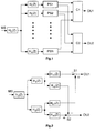
Fig. 1 zeigt ein Vierstufensystem. Ein solches System kann durch analoge oder zeitdiskrete Techniken realisiert werden. Die erste Stufe besteht aus einem Kompensationsfilter Hc(z) für das Monosignal MS, welches den Signalfilterungseffekt (z.B. Frequenzgangfehler und/oder Phasengangfehler) der Filter in der folgenden Stufe kompensiert. Ohne das Kompensationsfilter Hc(z) ist die Summe Hi(z), i=1, ...,N, ungleich '1'. Ein gedachtes Mono-Ausgangssignal, welches ja per Definition die Hälfte aus der Summe des linken und des rechten Ausgangssignals ist, wäre nicht identisch mit dem Eingangssignal der gesamten Schaltung. Diese erste Stufe ist optional.Fig. 1 shows a four-stage system. Such a system can be implemented using analog or discrete-time techniques. The first stage consists of a compensation filter H c (z) for the mono signal MS, which compensates for the signal filtering effect (eg frequency response errors and / or phase response errors) of the filters in the following stage. Without the compensation filter H c (z) the sum H i (z), i = 1, ..., N, is not equal to '1'. A conceived mono output signal, which by definition is half of the sum of the left and right output signals, would not be identical to the input signal of the entire circuit. This first stage is optional.
Die folgende zweite Stufe besteht aus N aufeinander abgestimmten
Filtern H1(z), H2 (z), ..., HN(z), wobei N eine
ganze Zahl größer als eins ist und die Eingänge dieser Filter
vom Ausgangssignal des Kompensationsfilters Hc(z) gespeist
werden. Sehr gute Ergebnisse können schon mit N = 2
erreicht werden. Diese Filter generieren mehrere verschiedenartige
Kanäle und können entweder eine solche Charakteristik
haben, daß sie das Eingangssignal in mehrere Frequenzbänder
aufspalten oder sie können eine Wichtung über der
Frequenz herbeiführen, d.h. manche Frequenzbereiche relativ
zu anderen abschwächen. Im ersten Fall sind die Filter so
entworfen, daß sie die Frequenzbänder so effektiv wie möglich
separieren, während im zweiten Fall jedes Filter so
entworfen ist, daß nur gewisse Frequenzbänder verstärkt werden
aber kein Frequenzband praktisch vollständig ausgefiltert
wird.
Beim Entwurf der Filter Hi(z), i=1, ...,N, gibt es z.B. die
zwei folgenden Optionen:
When designing the filters H i (z), i = 1, ..., N, there are two options, for example:
Die dritte Stufe besteht aus einigen, den abgestimmten Filtern H1(z), H2 (z), ..., HN(z) jeweils nachgeordneten Single-Band-Systemen PS1, PS2, ..., PSN, die in jedem Frequenzband separat verwendet werden, um künstliche Stereosignale oder um Mehrton-Signale mit mehr als zwei Kanälen zu erzeugen. Jedes der bekannten Single-Band-Verfahren kann hierfür verwendet werden, vorteilhaft ist das oben erwähnte Verfahren nach Lauridsen. Vorteilhaft werden die Parameter zur Generierung der Pseudostereo- oder Mehrton-Signale in jedem der Frequenzbänder verschieden gewählt, wodurch eine deutliche Verbesserung gegenüber Single-Band-Verfahren mit N=1 erreicht wird.The third stage consists of some, the coordinated filters H 1 (z), H 2 (z), ..., H N (z) each sub-band systems PS1, PS2, ..., PSN, which in Each frequency band can be used separately to generate artificial stereo signals or to generate multi-tone signals with more than two channels. Any of the known single-band processes can be used for this purpose, the Lauridsen process mentioned above being advantageous. The parameters for generating the pseudostereo or multi-tone signals are advantageously selected differently in each of the frequency bands, as a result of which a significant improvement over single-band methods with N = 1 is achieved.
Die Pseudo-Stereo- bzw. Mehrton-Ausgangssignale der Blöcke in der dritten Stufe werden in der vierten Stufe durch den Single-Band-Systemen PS1, PS2, ..., PSN nachgeordnete Kombinierstufen C1 und C2 erzeugt, die das linke OU1 und das rechte OU2 Ausgangssignal oder auch mittels weiterer solcher Kombinierstufen weitere Ausgangssignale formen. Diese Kombination kann additiv und/oder subtraktiv erfolgen, eventuell mit einer zusätzlichen Wichtung.The pseudo-stereo or multi-tone output signals of the blocks in the third stage in the fourth stage by the Single band systems PS1, PS2, ..., PSN downstream combination stages C1 and C2 generates the left OU1 and that right OU2 output signal or by means of other such Combination stages form further output signals. That combination can be additive and / or subtractive, possibly with an additional weight.
Ein Ausführungsbeispiel der Erfindung bezieht sich auf bestimme
Filterstrukturen und Parameter der Anordnung. Dazu
soll anhand von Fig. 2 ein zeitdiskretes System mit N = 2
und in der dritten Stufe mit dem Verfahren nach Lauridsen
betrachtet werden:
Die Werte 'k1' und 'k2' sind abschwächende Multiplikations-Faktoren
und haben bei fs = 48kHz Abtastfrequenz beispielsweise
einen Wert von
Die Frequenzwichtungsfilter sind in diesem Beispiel gegeben
durch
Das Kompensationsfilter wird dann zu:
Der Wert 'q' ist ein abschwächender Multiplikations-Faktor
und hat beispielsweise einen Wert von q = 0,6...0,75.
Das erste Ausgangssignal OU1 wird in einem ersten Subtrahierer
S1 durch Subtraktion des Ausgangssignals von H11(z) vom
Ausgangssignal von H21(z) erzeugt. Das zweite Ausgangssignal
OU2 wird in einem zweiten Subtrahierer S2 durch Subtraktion
des Ausgangssignals von H12(z) vom Ausgangssignal von H22(z)
erzeugt.
Vorteilhaft werden die Werte für k1, k2, N1, N2 und q je
nach Programm-Material angepaßt, also z.B. unterschiedlich
für Musik und Sprache gewählt. Vorteilhaft werden k1 und k2
oder auch andere Werte bei Sprache kleiner gewählt als bei
Musik.The compensation filter then becomes:
The value 'q' is a weakening multiplication factor and has, for example, a value of q = 0.6 ... 0.75.
The first output signal OU1 is generated in a first subtractor S1 by subtracting the output signal from H 11 (z) from the output signal from H 21 (z). The second output signal OU2 is generated in a second subtractor S2 by subtracting the output signal from H 12 (z) from the output signal from H 22 (z).
The values for k1, k2, N1, N2 and q are advantageously adapted depending on the program material, that is, for example, selected differently for music and speech. K1 and k2 or other values for speech are advantageously chosen to be smaller than for music.
Die Erfindung liefert insbesondere für Pseudostereo eine gute
Qualität und kann z.B. in Stereo-Fernsehgeräten, in Stereo-Hörfunk-Empfängern
oder in PC's angewendet werden, um
aus einem empfangenen bzw. vorhandenen Monosignal ein Pseudostereo-Signal
zu generieren.
Statt Pseudostereo- bzw. Zweiton-Signalen können auch Mehrton-Signale
generiert werden, indem eine entsprechende zusätzliche
Anzahl von Kombinierern C1, C2, S1, S2 mit zusätzlichen
Kombinationsarten verwendet wird.The invention provides good quality in particular for pseudostereo and can be used, for example, in stereo television sets, in stereo radio receivers or in PCs in order to generate a pseudostereo signal from a received or existing mono signal.
Instead of pseudo-stereo or two-tone signals, multi-tone signals can also be generated by using a corresponding additional number of combiners C1, C2, S1, S2 with additional types of combinations.
Claims (10)
Applications Claiming Priority (2)
| Application Number | Priority Date | Filing Date | Title |
|---|---|---|---|
| DE19632734 | 1996-08-14 | ||
| DE19632734A DE19632734A1 (en) | 1996-08-14 | 1996-08-14 | Method and device for generating a multi-tone signal from a mono signal |
Publications (2)
| Publication Number | Publication Date |
|---|---|
| EP0825800A2 true EP0825800A2 (en) | 1998-02-25 |
| EP0825800A3 EP0825800A3 (en) | 2006-03-15 |
Family
ID=7802595
Family Applications (1)
| Application Number | Title | Priority Date | Filing Date |
|---|---|---|---|
| EP97113292A Withdrawn EP0825800A3 (en) | 1996-08-14 | 1997-08-01 | Method and apparatus for generating multi-audio signals from a mono audio signal |
Country Status (5)
| Country | Link |
|---|---|
| US (1) | US6005946A (en) |
| EP (1) | EP0825800A3 (en) |
| JP (1) | JPH1094098A (en) |
| CN (1) | CN1129346C (en) |
| DE (1) | DE19632734A1 (en) |
Cited By (5)
| Publication number | Priority date | Publication date | Assignee | Title |
|---|---|---|---|---|
| WO2001049073A2 (en) | 1999-12-24 | 2001-07-05 | Koninklijke Philips Electronics N.V. | Multichannel audio signal processing device |
| WO2009138205A1 (en) * | 2008-05-13 | 2009-11-19 | Clemens Par | Angle-dependent operating device or method for obtaining a pseudo-stereophonic audio signal |
| WO2011009650A1 (en) | 2009-07-22 | 2011-01-27 | Stormingswiss Gmbh | Device and method for optimizing stereophonic or pseudo-stereophonic audio signals |
| WO2012016992A2 (en) | 2010-08-03 | 2012-02-09 | Stormingswiss Gmbh | Device and method for evaluating and optimizing signals on the basis of algebraic invariants |
| WO2012032178A1 (en) | 2010-09-10 | 2012-03-15 | Stormingswiss Gmbh | Apparatus and method for the time-oriented evaluation and optimization of stereophonic or pseudo-stereophonic signals |
Families Citing this family (13)
| Publication number | Priority date | Publication date | Assignee | Title |
|---|---|---|---|---|
| US6829018B2 (en) | 2001-09-17 | 2004-12-07 | Koninklijke Philips Electronics N.V. | Three-dimensional sound creation assisted by visual information |
| DE602004005846T2 (en) * | 2003-04-17 | 2007-12-20 | Koninklijke Philips Electronics N.V. | AUDIO SIGNAL GENERATION |
| ES2281795T3 (en) * | 2003-04-17 | 2007-10-01 | Koninklijke Philips Electronics N.V. | SYNTHESIS OF AUDIO SIGNAL. |
| SE0301273D0 (en) * | 2003-04-30 | 2003-04-30 | Coding Technologies Sweden Ab | Advanced processing based on a complex exponential-modulated filter bank and adaptive time signaling methods |
| CN100396162C (en) * | 2004-07-14 | 2008-06-18 | 华南理工大学 | Signal processing method for three-loudspeaker virtual 5.1 channel surround sound |
| CN102833665B (en) * | 2004-10-28 | 2015-03-04 | Dts(英属维尔京群岛)有限公司 | Audio spatial environment engine |
| EP1691348A1 (en) * | 2005-02-14 | 2006-08-16 | Ecole Polytechnique Federale De Lausanne | Parametric joint-coding of audio sources |
| US7920708B2 (en) * | 2006-11-16 | 2011-04-05 | Texas Instruments Incorporated | Low computation mono to stereo conversion using intra-aural differences |
| US8019086B2 (en) * | 2006-11-16 | 2011-09-13 | Texas Instruments Incorporated | Stereo synthesizer using comb filters and intra-aural differences |
| EP2304721B1 (en) * | 2008-06-26 | 2012-05-09 | France Telecom | Spatial synthesis of multichannel audio signals |
| CN103534753B (en) * | 2012-04-05 | 2015-05-27 | 华为技术有限公司 | Method for inter-channel difference estimation and spatial audio coding device |
| US9338552B2 (en) | 2014-05-09 | 2016-05-10 | Trifield Ip, Llc | Coinciding low and high frequency localization panning |
| EP2980789A1 (en) * | 2014-07-30 | 2016-02-03 | Fraunhofer-Gesellschaft zur Förderung der angewandten Forschung e.V. | Apparatus and method for enhancing an audio signal, sound enhancing system |
Citations (2)
| Publication number | Priority date | Publication date | Assignee | Title |
|---|---|---|---|---|
| DE973570C (en) * | 1948-10-02 | 1960-03-31 | Siemens Ag | Device for the plastic reproduction of electroacoustic performances |
| US5301236A (en) * | 1992-01-13 | 1994-04-05 | Pioneer Electronic Corporation | System for producing stereo-simulated signals for simulated-stereophonic sound |
Family Cites Families (3)
| Publication number | Priority date | Publication date | Assignee | Title |
|---|---|---|---|---|
| US4555795A (en) * | 1982-07-22 | 1985-11-26 | Tvi Systems, Ltd. | Monaural to binaural audio processor |
| US5235646A (en) * | 1990-06-15 | 1993-08-10 | Wilde Martin D | Method and apparatus for creating de-correlated audio output signals and audio recordings made thereby |
| JP2979848B2 (en) * | 1992-07-01 | 1999-11-15 | ヤマハ株式会社 | Electronic musical instrument |
-
1996
- 1996-08-14 DE DE19632734A patent/DE19632734A1/en not_active Withdrawn
-
1997
- 1997-08-01 EP EP97113292A patent/EP0825800A3/en not_active Withdrawn
- 1997-08-11 JP JP9216637A patent/JPH1094098A/en active Pending
- 1997-08-11 US US08/909,773 patent/US6005946A/en not_active Expired - Fee Related
- 1997-08-13 CN CN97117358.3A patent/CN1129346C/en not_active Expired - Fee Related
Patent Citations (2)
| Publication number | Priority date | Publication date | Assignee | Title |
|---|---|---|---|---|
| DE973570C (en) * | 1948-10-02 | 1960-03-31 | Siemens Ag | Device for the plastic reproduction of electroacoustic performances |
| US5301236A (en) * | 1992-01-13 | 1994-04-05 | Pioneer Electronic Corporation | System for producing stereo-simulated signals for simulated-stereophonic sound |
Non-Patent Citations (1)
| Title |
|---|
| SCHROEDER M R: "AN ARTIFICIAL STEREOPHONIC EFFECT OBTAINED FROM A SINGLE AUDIO SIGNAL" JOURNAL OF THE AUDIO ENGINEERING SOCIETY, AUDIO ENGINEERING SOCIETY, NEW YORK, NY, US, Bd. 6, Nr. 2, 1. April 1958 (1958-04-01), Seiten 74-79, XP000604521 ISSN: 1549-4950 * |
Cited By (12)
| Publication number | Priority date | Publication date | Assignee | Title |
|---|---|---|---|---|
| WO2001049073A2 (en) | 1999-12-24 | 2001-07-05 | Koninklijke Philips Electronics N.V. | Multichannel audio signal processing device |
| WO2009138205A1 (en) * | 2008-05-13 | 2009-11-19 | Clemens Par | Angle-dependent operating device or method for obtaining a pseudo-stereophonic audio signal |
| EP2124486A1 (en) * | 2008-05-13 | 2009-11-25 | Clemens Par | Angle-dependent operating device or method for generating a pseudo-stereophonic audio signal |
| US8638947B2 (en) | 2008-05-13 | 2014-01-28 | Stormingswiss Gmbh | Angle-dependent operating device or method for generating a pseudo-stereophonic audio signal |
| CN102100089B (en) * | 2008-05-13 | 2014-10-01 | 斯托明瑞士有限责任公司 | Angle-dependent operating device or method for obtaining a pseudo-stereophonic audio signal |
| WO2011009650A1 (en) | 2009-07-22 | 2011-01-27 | Stormingswiss Gmbh | Device and method for optimizing stereophonic or pseudo-stereophonic audio signals |
| CN102484763A (en) * | 2009-07-22 | 2012-05-30 | 斯托明瑞士有限责任公司 | Device and method for optimizing stereophonic or pseudo-stereophonic audio signals |
| US8958564B2 (en) | 2009-07-22 | 2015-02-17 | Stormingswiss Gmbh | Device and method for improving stereophonic or pseudo-stereophonic audio signals |
| CN102484763B (en) * | 2009-07-22 | 2016-01-06 | 斯托明瑞士有限责任公司 | For equipment and the method for optimizing stereophonic or pseudo-stereophonic audio signals |
| US9357324B2 (en) | 2009-07-22 | 2016-05-31 | Stormingswiss Gmbh | Device and method for optimizing stereophonic or pseudo-stereophonic audio signals |
| WO2012016992A2 (en) | 2010-08-03 | 2012-02-09 | Stormingswiss Gmbh | Device and method for evaluating and optimizing signals on the basis of algebraic invariants |
| WO2012032178A1 (en) | 2010-09-10 | 2012-03-15 | Stormingswiss Gmbh | Apparatus and method for the time-oriented evaluation and optimization of stereophonic or pseudo-stereophonic signals |
Also Published As
| Publication number | Publication date |
|---|---|
| CN1129346C (en) | 2003-11-26 |
| DE19632734A1 (en) | 1998-02-19 |
| EP0825800A3 (en) | 2006-03-15 |
| US6005946A (en) | 1999-12-21 |
| CN1175182A (en) | 1998-03-04 |
| JPH1094098A (en) | 1998-04-10 |
Similar Documents
| Publication | Publication Date | Title |
|---|---|---|
| DE69819090T2 (en) | compensating filter | |
| EP0825800A2 (en) | Method and apparatus for generating multi-audio signals from a mono audio signal | |
| DE2806914C2 (en) | Sound reproduction system | |
| DE69433258T2 (en) | Surround sound signal processing device | |
| DE69832595T2 (en) | MULTIPLE AUDIO DECODER | |
| DE69827775T2 (en) | TONKANALSMISCHUNG | |
| DE2720984C3 (en) | Electrical arrangement for increasing the spatial effect in sound reproduction | |
| DE69921532T2 (en) | Synthesis of surround sound QSOUND from stereo signals | |
| EP0905933A2 (en) | Method and system for mixing audio signals | |
| DE2407406A1 (en) | FREQUENCY MULTIPLEX SYSTEM | |
| DE19715498A1 (en) | Stereo acoustic image enhancement device | |
| DE102007046025A1 (en) | Signal processing device i.e. audio playback device, has combination circuit combining input audio signal, two harmonic component signals in preset ratio, where frequency band of one frequency component is higher than other frequency band | |
| DE3630692C2 (en) | ||
| DE112007003683B4 (en) | Echo cancellation system, echo cancellation method, sound output device, audio system, navigation system and mobile object | |
| DE3040896C2 (en) | Circuit arrangement for generating and processing stereophonic signals from a monophonic signal | |
| DE3806915C2 (en) | ||
| DE102008056704B4 (en) | Method for generating a backwards compatible sound format | |
| EP0808076B1 (en) | Surround sound system | |
| DE102012224454A1 (en) | Generation of 3D audio signals | |
| EP0776144B1 (en) | Signal modification circuit | |
| DE19645867A1 (en) | Multiple channel sound transmission method | |
| DE3142157C2 (en) | ||
| DE112006002548T5 (en) | Apparatus and method for playing two-channel virtual sound | |
| EP0156334A2 (en) | Method and device for simulating (electronic artificial head) the free-field transmission characteristics of the ear | |
| DE19980688B3 (en) | Audio playback device |
Legal Events
| Date | Code | Title | Description |
|---|---|---|---|
| PUAI | Public reference made under article 153(3) epc to a published international application that has entered the european phase |
Free format text: ORIGINAL CODE: 0009012 |
|
| AK | Designated contracting states |
Kind code of ref document: A2 Designated state(s): AT BE CH DE DK ES FI FR GB GR IE IT LI LU MC NL PT SE |
|
| PUAL | Search report despatched |
Free format text: ORIGINAL CODE: 0009013 |
|
| AK | Designated contracting states |
Kind code of ref document: A3 Designated state(s): AT BE CH DE DK ES FI FR GB GR IE IT LI LU MC NL PT SE |
|
| 17P | Request for examination filed |
Effective date: 20060415 |
|
| 17Q | First examination report despatched |
Effective date: 20060621 |
|
| AKX | Designation fees paid |
Designated state(s): DE FR GB IT |
|
| STAA | Information on the status of an ep patent application or granted ep patent |
Free format text: STATUS: THE APPLICATION IS DEEMED TO BE WITHDRAWN |
|
| 18D | Application deemed to be withdrawn |
Effective date: 20061104 |