EP0905467A2 - Evaporator - Google Patents
Evaporator Download PDFInfo
- Publication number
- EP0905467A2 EP0905467A2 EP98117944A EP98117944A EP0905467A2 EP 0905467 A2 EP0905467 A2 EP 0905467A2 EP 98117944 A EP98117944 A EP 98117944A EP 98117944 A EP98117944 A EP 98117944A EP 0905467 A2 EP0905467 A2 EP 0905467A2
- Authority
- EP
- European Patent Office
- Prior art keywords
- refrigerant
- header
- portions
- path
- evaporator
- Prior art date
- Legal status (The legal status is an assumption and is not a legal conclusion. Google has not performed a legal analysis and makes no representation as to the accuracy of the status listed.)
- Granted
Links
Images


Classifications
-
- F—MECHANICAL ENGINEERING; LIGHTING; HEATING; WEAPONS; BLASTING
- F28—HEAT EXCHANGE IN GENERAL
- F28F—DETAILS OF HEAT-EXCHANGE AND HEAT-TRANSFER APPARATUS, OF GENERAL APPLICATION
- F28F9/00—Casings; Header boxes; Auxiliary supports for elements; Auxiliary members within casings
- F28F9/02—Header boxes; End plates
- F28F9/026—Header boxes; End plates with static flow control means, e.g. with means for uniformly distributing heat exchange media into conduits
- F28F9/027—Header boxes; End plates with static flow control means, e.g. with means for uniformly distributing heat exchange media into conduits in the form of distribution pipes
-
- F—MECHANICAL ENGINEERING; LIGHTING; HEATING; WEAPONS; BLASTING
- F25—REFRIGERATION OR COOLING; COMBINED HEATING AND REFRIGERATION SYSTEMS; HEAT PUMP SYSTEMS; MANUFACTURE OR STORAGE OF ICE; LIQUEFACTION SOLIDIFICATION OF GASES
- F25B—REFRIGERATION MACHINES, PLANTS OR SYSTEMS; COMBINED HEATING AND REFRIGERATION SYSTEMS; HEAT PUMP SYSTEMS
- F25B39/00—Evaporators; Condensers
- F25B39/02—Evaporators
- F25B39/022—Evaporators with plate-like or laminated elements
-
- F—MECHANICAL ENGINEERING; LIGHTING; HEATING; WEAPONS; BLASTING
- F28—HEAT EXCHANGE IN GENERAL
- F28D—HEAT-EXCHANGE APPARATUS, NOT PROVIDED FOR IN ANOTHER SUBCLASS, IN WHICH THE HEAT-EXCHANGE MEDIA DO NOT COME INTO DIRECT CONTACT
- F28D1/00—Heat-exchange apparatus having stationary conduit assemblies for one heat-exchange medium only, the media being in contact with different sides of the conduit wall, in which the other heat-exchange medium is a large body of fluid, e.g. domestic or motor car radiators
- F28D1/02—Heat-exchange apparatus having stationary conduit assemblies for one heat-exchange medium only, the media being in contact with different sides of the conduit wall, in which the other heat-exchange medium is a large body of fluid, e.g. domestic or motor car radiators with heat-exchange conduits immersed in the body of fluid
- F28D1/03—Heat-exchange apparatus having stationary conduit assemblies for one heat-exchange medium only, the media being in contact with different sides of the conduit wall, in which the other heat-exchange medium is a large body of fluid, e.g. domestic or motor car radiators with heat-exchange conduits immersed in the body of fluid with plate-like or laminated conduits
- F28D1/0308—Heat-exchange apparatus having stationary conduit assemblies for one heat-exchange medium only, the media being in contact with different sides of the conduit wall, in which the other heat-exchange medium is a large body of fluid, e.g. domestic or motor car radiators with heat-exchange conduits immersed in the body of fluid with plate-like or laminated conduits the conduits being formed by paired plates touching each other
- F28D1/0325—Heat-exchange apparatus having stationary conduit assemblies for one heat-exchange medium only, the media being in contact with different sides of the conduit wall, in which the other heat-exchange medium is a large body of fluid, e.g. domestic or motor car radiators with heat-exchange conduits immersed in the body of fluid with plate-like or laminated conduits the conduits being formed by paired plates touching each other the plates having lateral openings therein for circulation of the heat-exchange medium from one conduit to another
- F28D1/0333—Heat-exchange apparatus having stationary conduit assemblies for one heat-exchange medium only, the media being in contact with different sides of the conduit wall, in which the other heat-exchange medium is a large body of fluid, e.g. domestic or motor car radiators with heat-exchange conduits immersed in the body of fluid with plate-like or laminated conduits the conduits being formed by paired plates touching each other the plates having lateral openings therein for circulation of the heat-exchange medium from one conduit to another the plates having integrated connecting members
- F28D1/0341—Heat-exchange apparatus having stationary conduit assemblies for one heat-exchange medium only, the media being in contact with different sides of the conduit wall, in which the other heat-exchange medium is a large body of fluid, e.g. domestic or motor car radiators with heat-exchange conduits immersed in the body of fluid with plate-like or laminated conduits the conduits being formed by paired plates touching each other the plates having lateral openings therein for circulation of the heat-exchange medium from one conduit to another the plates having integrated connecting members with U-flow or serpentine-flow inside the conduits
-
- F—MECHANICAL ENGINEERING; LIGHTING; HEATING; WEAPONS; BLASTING
- F28—HEAT EXCHANGE IN GENERAL
- F28F—DETAILS OF HEAT-EXCHANGE AND HEAT-TRANSFER APPARATUS, OF GENERAL APPLICATION
- F28F3/00—Plate-like or laminated elements; Assemblies of plate-like or laminated elements
- F28F3/02—Elements or assemblies thereof with means for increasing heat-transfer area, e.g. with fins, with recesses, with corrugations
- F28F3/04—Elements or assemblies thereof with means for increasing heat-transfer area, e.g. with fins, with recesses, with corrugations the means being integral with the element
Definitions
- the present invention relates to evaporators for use in air conditioners for motor vehicles.
- Evaporators for use in motor vehicle air conditioners and the like which comprise first and second header portions arranged in parallel, and flat tubular portions arranged in parallel and each connected at opposite ends thereof to the header portions, each of the header portions being provided with a partition for blocking a refrigerant flowing inside thereof and directing the refrigerant toward some of the flat tubular portions to thereby form a refrigerant channel comprising a first path, at least one intermediate path and a final path.
- the number of paths i.e., the number of blocking partitions
- the refrigerant passing apertures are reduced in area, and the refrigerant is moved from path to path at an increased rate, impairing the division of the refrigerant in a downstream path (especially in the final path) and permitting the refrigerant to unevenly pass through the flat tubular portions providing this path, with an increased amount of the refrigerant flowing through the flat tubular portion at the downstream extremity.
- This imposes a limitation an the improvement of the cooling ability.
- An object of the present invention is to provide an evaporator wherein the division of the refrigerant into separate flows in a downstream path is optimized by a method other than varying the number of paths so as to give high cooling ability to the evaporator.
- the present invention provides an evaporator which comprises first and second header portions arranged in parallel, and flat tubular portions arranged in parallel and each connected at opposite ends thereof to the header portions, each of the header portions being provided with a partition for blocking a refrigerant flowing inside thereof and directing the refrigerant toward some of the flat tubular portions to thereby form a refrigerant channel comprising a first path, at least one intermediate path and a final path, the evaporator being characterized in that at least one of the header portions is provided with at least one refrigerant dividing wall having at least one refrigerant aperture for passing therethrough a portion of the refrigerant flowing from one of the paths into the path downstream from said one path, with the remaining portion of the refrigerant blocked by the wall and directed toward some of the flat tubular portions.
- the refrigerant flowing out from one path into the first header portion of the path immediately downstream from the former path partly passes through the refrigerant aperture of the dividing wall to reach the downstream part of the first header portion of the downstream path and thereafter flows through the flat tubular portions in communication with the downstream part into the downstream part of the second header portion of the downstream path.
- the portion of the refrigerant blocked by the dividing wall flows through the flat tubular portions in the upstream part of the downstream path into the upstream part of the second header portion of the downstream path.
- the portions of the refrigerant divided by the wall join together inside the second header portion, and the combined refrigerant flows out of the second header portion into the path which is positioned further downstream. Accordingly, a greater quantity of refrigerant flows through the flat tubular portions in the upstream part of the downstream path than when the evaporator has no refrigerant dividing wall, consequently giving a uniform distribution of refrigerant temperatures throughout the entire evaporator to result in improved cooling ability.
- the same result is achieved in the case where one refrigerant dividing wall is provided in the second header portion and in the case where one refrigerant dividing wall is provided in each of the header portions.
- the evaporator exhibits a uniform distribution of refrigerant temperatures in its entirety and improved cooling ability unlike evaporators having no refrigerant dividing wall.
- the final path causes the refrigerant to turn at a closed end of the first header portion and to flow out of an end of the second header portion which end has a refrigerant outlet, and the refrigerant dividing wall is singly provided in the first header portion of the final path.
- the refrigerant flowing into the first header portion of the final path partly passes through the refrigerant aperture of the dividing wall to reach the downstream part of the first header portion of the final path and thereafter flows through the flat tubular portions in communication with the downstream part into the downstream part of the second header portion of the final path.
- the portion of the refrigerant blocked by the dividing wall flows through the flat tubular portions in the upstream part of the final path into the upstream part of the second header portion of the final path.
- the portions of the refrigerant divided by the wall join together inside the second header portion, and the combined refrigerant flows out of the refrigerant outlet of the second header portion.
- the refrigerant dividing wall has one to six refrigerant apertures. If the number of apertures is greater than six, the wall requires much labor for machining, while a uniform distribution of refrigerant temperatures will not be achieved effectively.
- the refrigerant apertures are arranged in a plurality of pairs, and each pair of refrigerant apertures are positioned symmetrically. This arrangement obviates occurrence of an uneven flow inside the header portion, consequently eliminating the disadvantage resulting from the provision of the refrigerant apertures.
- the refrigerant apertures are circular and have a diameter preferably of 2.5 to 4.0 mm.
- the diameter of the refrigerant apertures is 3.0 to 3.5 mm.
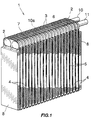
- An evaporator 1 embodying the invention is made of aluminum (including an aluminum alloy) and comprises U-shaped flat tubular portions 5 arranged in parallel, and front and rear header portions 6, 7, these portions being formed by fitting together intermediate plates 2, 3, 3A, 3B, 3C as will be described later.
- Corrugated fins 4 are interposed between each pair of adjacent flat tubular portions 5.
- a side plate 8 is fitted to each of opposite outer sides of the assembly of intermediate plates 2, 3, 3A, 3B, 3C fitted together.
- Corrugated fins 4 are provided also between the side plate 8 and the tubular portions 5 adjacent thereto.
- Connected to the right end of the rear header portion 7 is a refrigerant inlet pipe 10 having an inner pipe portion 10a.
- a refrigerant outlet pipe 11 is joined to the right end of the front header portion 6.
- the intermediate plates 2, 3, 3A, 3B, 3C are end intermediate plates 2 arranged at the left and right ends of the evaporator 1, a rear header partitioning intermediate plate 3A positioned at a distance of about 1/3 of the length of the evaporator rightward from the left end, a front header partitioning intermediate plate 3B disposed at a distance of about 1/3 of the length leftward from the right end, a refrigerant dividing wall forming intermediate plate 3C positioned at a distance of about 1/6 of the length leftward from the right end, and the remaining plates, i.e., standard intermediate plates 3.
- the standard intermediate plate 3 and the end intermediate plate 2 are paired. The number of plates shown in FIG.
- the evaporator has, for example, 21 pairs of plates in total: one of the seventh pair of plates from the left end may serve as the rear header partitioning intermediate plate 3A, one of the seventh pair of plates from the right end may serve as the front header partitioning intermediate plate 3B, and one of the fourth pair of plates from the right end may serve as the refrigerant dividing wall forming intermediate plate 3C.
- FIG. 4 shows one pair of standard intermediate plates 3.
- the intermediate plate 3 comprises a generally U-shaped flat tube forming recessed portion 21 including a front vertical portion 21a, a rear vertical portion 21b and a horizontal portion 21 interconnecting these portions 21a, 21b; and front and rear header forming recessed portions 22, 23 integral with the upper ends of the respective front and rear vertical portions 21a, 21b and having a greater depth than the recessed portion 21.
- Two refrigerant apertures 24, 25, each in the form of a circle elongated transversely of the evaporator, are formed in the standard plate 3, respectively in the bottom walls 22a, 23a of the header forming recessed portions 22, 23.
- the tube forming recessed portion 21 of the intermediate plate 3 is centrally formed with a vertical long ridge 26 extending from the upper end of the recessed portion 21 to a position close to the lower end thereof for providing a U-shaped refrigerant channel.
- the recessed portions 21 thereof provide one flat tubular portion 5.
- Inner fin members 29 having parallel vertical passages are interposed between the bottom walls of front and rear vertical portions 21a, 21b of the tube forming recessed portions 21 of the pair of intermediate plates 3, whereby vertical parallel passageways are formed in the flat tubular portion 5 as seen in FIG. 5.
- the bottom wall of horizontal portion 21c of the tube forming recessed portion 21 is provided with a quadrant protrusion 27 for forming a semicircular arc turn portion for holding the front vertical portion of the flat tubular portion 5 in communication with the rear vertical portion thereof, and generally triangular protrusions 28 arranged at the front and rear sides of lower part of the horizontal portion 21c for reinforcing the corresponding corners of the plate 3 and permitting the refrigerant to flow through the turn portion smoothly.
- a projecting edge 25a is formed by burring on the peripheral part around the refrigerant aperture 25 of the rear header forming recessed portion 23 of the plate 3 at left in FIG. 4.
- a projecting edge 24a is formed by burring on the peripheral part around the refrigerant aperture 24 of the front header forming recessed portion 22 of the plate 3 at right in FIG. 4 (see FIG. 2). These projecting edges 24a, 25a are fitted in the refrigerant apertures 24, 25 of the header forming recessed portions 22, 23 adjacent thereto as seen in FIG. 2, whereby the intermediate plates 3 concerned are reliably positioned in place relative to one another.
- the inner fin member 29 may be replaced by a plurality of ridges formed on the bottom wall of each of the front and rear vertical portions 21a, 21b of the tube forming recessed portion 21 so as to form straight small passageways in the tubular portion 5.
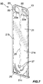
- FIG. 6 shows the rear header partitioning intermediate plate 3A.
- the intermediate plate 3A has a front header forming recessed portion 22 which is formed in its bottom wall 22a with a refrigerant aperture 24 generally in the form of a circle elongated transversely of the evaporator, and a rear header forming recessed portion 23 which is farmed in its bottom wall 23a with a through hole 30 having a diameter equal to the outside diameter of the inner pipe portion 10a of the refrigerant inlet pipe 10.
- the bottom wall 23a of the recessed portion 23 serves as a rear header partition 12.
- the bottom wall edge defining the through hole 30 is burred so as to give an increased area of contact with the pipe portion 10a.
- the intermediate plate 3A has the same construction as the standard intermediate plate 3 with the exception of the above feature, and like parts are designated by like reference numerals and will not be described repeatedly.
- FIG. 7 shows the front header partitioning intermediate plate 3C.
- the intermediate plate 3B has a rear header forming recessed portion 23 which is formed in its bottom wall 23a with a refrigerant aperture 25 generally in the form of a circle elongated transversely of the evaporator, and a front header forming recessed portion 22 which is formed with no refrigerant aperture in its bottom wall 22a.
- the bottom wall 22a having no aperture serves as a front header partition 13.
- the intermediate plate 3B has the same construction as the standard intermediate plate 3 with the exception of the above feature, and like parts are designated by like reference numerals and will not be described repeatedly.
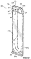
- FIG. 8 shows the refrigerant dividing wall forming intermediate plate 3C.
- the intermediate plate 3C has a front header forming recessed portion 22 which is formed in its bottom wall 22a with a refrigerant aperture 24 generally in the form of a circle elongated transversely of the evaporator, and a rear header forming recessed portion 23 which is formed in its bottom wall 23a with a through hole 30 having a diameter equal to the outside diameter of the inner pipe portion 10a of the refrigerant inlet pipe 10 and with two refrigerant apertures 31 respectively at the front and rear sides of the hole 30.
- apertures 31 are small, so that when the inner pipe portion 10a is inserted through the hole 30, the refrigerant flowing rightward in the rear header portion 7 partly passes through the apertures 31 as indicated by solid arrows in FIG. 2, while the remaining portion of the refrigerant is blocked by the bottom plate 23a and directed toward the U-shaped flat tubular portion 5 as indicated by an arrow of broken line.
- the bottom wall 23a, having the apertures 31, of the rear header forming recessed portion 23 serves as a refrigerant dividing wall 14.
- FIG. 9 shows the left end intermediate plate 2 and the standard intermediate plate 3 paired therewith.
- the left end plate 2 has front and rear header forming recessed portions 22, 23 which are formed in their bottom walls 22a, 23a with no refrigerant aperture.
- Two U-shaped reinforcing plates 15 are provided between, and fitted to, each of the left and right end intermediate plates 2 and the standard intermediate plate 3 paired therewith, each of the reinforcing plates 15 being fitted to the lower half of inner periphery of peripheral wall of each recessed portion 22 (23).
- the reinforcing plate 15 has a width equal to the depth of the recessed portion 22 (23) of the end plate 2 plus the depth of the recessed portion 22 (23) of the standard plate 3.
- the reinforcing plate 15 is formed with a plurality of refrigerant apertures 15a for holding the header portion 6 (7) in communication with the flat tubular portion 5.
- the bottom wall 22a of the front header forming recessed portion 22 is formed with a through hole serving as a refrigerant outlet 32 and having a diameter equal to the outside diameter of the refrigerant outlet pipe 11, and the bottom wall 23a the rear header forming recessed portion 23 is formed with a through hole 30 having a diameter equal to the outside diameter of inner pipe portion 10a of the refrigerant inlet pipe 10.
- the intermediate plates 2, 3, 3A, 3B, 3C are arranged side by side and fittingly joined to one another, with their recessed portions 21, 22, 23 facing toward opposite directions alternately, whereby the parallel U-shaped flat tubular portions 5 and the front and rear header portions 6, 7 are formed.
- the front and rear header portions 6, 7 are formed with the respective partitions 12,13 for blocking the refrigerant flowing rightward in the portions 6, 7 and directing the refrigerant toward U-shaped flat tubular portions 5, while the refrigerant dividing wall 14 is formed in the vicinity of the roar header portion 7.
- the refrigerant inlet pipe 10 extends through the rear header partitioning intermediate plate 3A and has a left end opening which is positioned within the left end portion 7a of the rear header portion 7.
- the inner pipe portion 10a of the refrigerant inlet pipe 10 extends through an intermediate portion 7b and the right end portion 7c of the rear header portion 7, with a refrigerant passing clearance formed in each refrigerant aperture 25 around the pipe portion 10a.
- the evaporator 1 can be prepared by collectively brazing the components including the reinforcing plates 15 provided between each end intermediate plate 2 and the standard intermediate plate 3 adjacent thereto.
- the presence of the reinforcing plates 15 given an improved strength to the evaporator 1 against the internal pressure thereof, making it possible to reduce the wall thickness of the side plates 8 and the inner fin members 29.
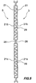
- the evaporator 1 thus constructed has in its interior three paths as shown in FIGS. 2 and 3: a first path 16 extending from the left end portion 7a of the rear head portion 7 through U-shaped flat tubular portions 5a in communication with the portion 7a to the left end portion 6a of the front header portion 6, an intermediate path 17 extending from an intermediate portion 6b of the front header portion 6 through U-shaped flat tubular portions 5b in communication with the portion 6b to the intermediate portion 7b of the rear header portion 7, and a final path 18 extending from the right end portion 7c of the rear header portion 7 through U-shaped flat tubular portions 5c in communication with the portion 7c to the right end portion 6c of the front header portion 6.
- These paths provide a zigzag refrigerant channel 16, 17, 18.
- the presence of the refrigerant dividing wall 14 separates the final path 18 into a first branch portion 18a and a second branch portion 18b, the first branch portion 18a extending from flat tubular portions c in the left portion (upstream portion) of the final path 18 to the left portion (upstream portion) of front header 6c of the final path 18, the second branch portion 18b extending from U-shaped flat tubular portions 5c in the right portion (downstream portion) of the final path 18 to the right portion (downstream portion) of front header portion 6c of the final path 18.
- the refrigerant flowing into the rear header portion 7c is divided into a portion flowing through the first branch portion 18a, and a portion flowing through the second branch portion 18b, and these refrigerant portions join within the front header portion 6c to flow out through the outlet pipe 11.
- the evaporator has the problem that an increased quantity of refrigerant flows into flat tubular portion at the right end of the final path, hence a limitation to the improvement of the cooling effect.
- the air passing through the right half of the evaporator is sent, for example, toward the driver's seat, and the air passing through the left half thereof toward the passenger's seat.
- the temperature of the air to be sent out is approximately equal at left and right even in this case, obviating the likelihood that for example, the passenger's seat will be cooled to excess, with the driver's seat cooled insufficiently, namely, the likelihood of imbalance occurring between opposite sides of the motor vehicle.
- FIG. 10 shows another preferred embodiment of refrigerant dividing wall forming intermediate plate 3C.
- the plate 3C shown in the drawing has two refrigerant apertures 31 formed at each of the front and rear sides of the through hole 30 in the front header forming recessed portion 23.
- the refrigerant apertures 31 are arranged at the front and rear sides symmetrically with respect to a vertical axis.
- the refrigerant apertures 31 are preferably up to six in number.
- the apertures be in one to three pairs, with each pair arranged symmetrically with respect to a vertical axis.
- the refrigerant apertures 31 are preferably 2.5 to 4.0 mm, more preferably 3.0 to 3.5 mm, in diameter.
- the path provided with the refrigerant dividing well 14 is not limited to the final path 18; the wall may be provided in the path immediately preceding the final path or in each of these paths.
- the refrigerant dividing wall can be modified variously in construction insofar as the wall partly blocks the refrigerant in one path and partly deflects the refrigerant toward flat tubular portions to thereby increase the quantity of refrigerant to be passed through the flat tubular portions in the upstream portion of that path.
- partitions 13, 12 are provided respectively in the front and rear header portions 6, 7, one in each header portion, two partitions can be provided in each of the front and rear header portions 6, 7 to provide five paths.
- the refrigerant inlet pipe 10 has the inner pipe portion 10a according to the foregoing embodiment, whereas the inner pipe portion can be omitted.
- the refrigerant inlet pipe is connected to the left end of the rear header portion 7, and the through holes 30 in the rear header partitioning plate 3A and the refrigerant dividing wall forming plate 3C for inserting the inner pipe portion 10a are closed.
- the present invention is applied to an evaporator of the vertical type wherein flat tubular portions are arranged side by side as positioned vertically according to the foregoing embodiment, the invention is similarly applicable also to an evaporator of the horizontal type wherein flat tubular portions are arranged in parallel as positioned horizontally.
- the front, rear and the left, right in the above embodiment are determined for the sake of convenience; the front-rear or the left-right relationship can of course be reversed.
- the type of evaporator is not limited to the single-tank layered evaporator but the invention is useful for evaporators which comprise a pair of header portions 7, 6 arranged in parallel, and flat tubular portions 5 arranged side by side and each connected at its opposite ends to the header portions 7, 6, the header portions 7, 6 being provided with respective partitions 12, 13 for blocking the refrigerant flowing through the portions 7, 6 and directing the refrigerant toward flat tubular portions 5 to thereby form a refrigerant channel comprising a first path 16, at least one intermediate path 17 and a final path 18.
- At least one of the header portions 7, 6 is then provided with a refrigerant dividing wall 14 having refrigerant apertures 31 for passing therethrough a portion of the refrigerant flowing from the upstream path 16, 17 into the downstream path 17, 18 while blocking the remaining portion of the refrigerant for deflection toward flat tubular portions 5c.
- a refrigerant dividing wall 14 having refrigerant apertures 31 for passing therethrough a portion of the refrigerant flowing from the upstream path 16, 17 into the downstream path 17, 18 while blocking the remaining portion of the refrigerant for deflection toward flat tubular portions 5c.
- an increased amount of refrigerant then flows into the flat tubular portions in the upstream portion of the final path.
- the evaporator thus adapted has a uniform distribution Of refrigerant temperatures in its entirety to exhibit an improved cooling capacity.
- an upper header portion is provided by the rear header portion 7 of the above embodiment, and a lower header portion by the front header portion 6 of the embodiment, whereby an evaporator is readily available which has the same advantage as described above.
Abstract
Description
Claims (7)
- An evaporator comprising first and second header portions arranged in parallel, and flat tubular portions arranged in parallel and each connected at opposite ends thereof to the header portions, each of the header portions being provided with a partition for blocking a refrigerant flowing inside thereof and directing the refrigerant toward some of the flat tubular portions to thereby form a refrigerant channel comprising a first path, at least one intermediate path and a final path, the evaporator being characterized in that at least one of the header portions is provided with at least one refrigerant dividing wall having at least one refrigerant aperture for passing therethrough a portion of the refrigerant flowing from one of the paths into the path downstream from said one path, with the remaining portion of the refrigerant blocked by the wall and directed toward some of the flat tubular portions.
- An evaporator according to claim 1 wherein the final path causes the refrigerant to turn at a closed end of the first header portion and to flow out of an end of the second header portion which end has a refrigerant outlet, and the refrigerant dividing wall is singly provided in the first header portion of the final path.
- An evaporator according to claim 2 wherein a refrigerant inlet pipe has an inner pipe portion inside the header portion.
- An evaporator according to claim 1 wherein one to six refrigerant apertures are formed.
- An evaporator according to claim 4 wherein the refrigerant apertures are arranged in a plurality of pairs, and each pair of refrigerant apertures are positioned symmetrically.
- An evaporator according to claim 5 wherein the refrigerant apertures are circular and have a diameter of 2.5 to 4.0 mm.
- An evaporator according to claim 6 wherein the diameter of the refrigerant apertures is 3.0 to 3.5 mm.
Applications Claiming Priority (3)
| Application Number | Priority Date | Filing Date | Title |
|---|---|---|---|
| JP25819297 | 1997-09-24 | ||
| JP258192/97 | 1997-09-24 | ||
| JP25819297 | 1997-09-24 |
Publications (3)
| Publication Number | Publication Date |
|---|---|
| EP0905467A2 true EP0905467A2 (en) | 1999-03-31 |
| EP0905467A3 EP0905467A3 (en) | 1999-08-04 |
| EP0905467B1 EP0905467B1 (en) | 2003-06-18 |
Family
ID=17316799
Family Applications (1)
| Application Number | Title | Priority Date | Filing Date |
|---|---|---|---|
| EP98117944A Expired - Lifetime EP0905467B1 (en) | 1997-09-24 | 1998-09-22 | Evaporator |
Country Status (5)
| Country | Link |
|---|---|
| US (1) | US6145587A (en) |
| EP (1) | EP0905467B1 (en) |
| AT (1) | ATE243309T1 (en) |
| DE (1) | DE69815616T2 (en) |
| ES (1) | ES2202707T3 (en) |
Cited By (6)
| Publication number | Priority date | Publication date | Assignee | Title |
|---|---|---|---|---|
| WO2002031424A1 (en) * | 2000-10-10 | 2002-04-18 | Dana Canada Corporation | Heat exchangers with flow distributing orifice partitions |
| FR2826438A1 (en) * | 2001-06-20 | 2002-12-27 | Valeo Climatisation | ARRANGEMENT OF INPUT AND OUTPUT TUBES FOR AN EVAPORATOR |
| WO2003087692A1 (en) * | 2002-04-10 | 2003-10-23 | Dana Canada Corporation | Heat exchanger inlet tube with flow distributing turbulizer |
| DE10257767A1 (en) * | 2002-12-10 | 2004-06-24 | Behr Gmbh & Co. Kg | Heat exchanger for condenser or gas cooler for air conditioning installations has two rows of channels for coolant with manifolds at ends and has ribs over which air can flow |
| CN104913548A (en) * | 2015-06-26 | 2015-09-16 | 上海交通大学 | Parallel flow heat exchanger of single header pipe |
| FR3028022A1 (en) * | 2014-10-30 | 2016-05-06 | Valeo Systemes Thermiques | TWO-CHANNEL AIR FLOW GUIDE SYSTEM COMPRISING A HEAT EXCHANGER |
Families Citing this family (13)
| Publication number | Priority date | Publication date | Assignee | Title |
|---|---|---|---|---|
| JP2001021287A (en) * | 1999-07-08 | 2001-01-26 | Zexel Valeo Climate Control Corp | Heat exchanger |
| WO2002073114A1 (en) * | 2001-03-14 | 2002-09-19 | Showa Denko K.K. | Layered heat exchanger, layered evaporator for motor vehicle air conditioners and refrigeration system |
| FR2826439B1 (en) * | 2001-06-26 | 2003-10-03 | Valeo Climatisation | HEAT EXCHANGER, PARTICULARLY EVAPORATOR, WITH IMPROVED PERFERMANCE |
| ATE412863T1 (en) * | 2001-12-21 | 2008-11-15 | Behr Gmbh & Co Kg | HEAT EXCHANGER, PARTICULARLY FOR A MOTOR VEHICLE |
| AU2003208623A1 (en) * | 2002-02-28 | 2003-09-09 | Showa Denko K.K. | Evaporator and refrigeration cycle |
| DE10243522A1 (en) * | 2002-09-19 | 2004-04-01 | Modine Manufacturing Co., Racine | Plate heat exchangers |
| CA2420273A1 (en) * | 2003-02-27 | 2004-08-27 | Peter Zurawel | Heat exchanger plates and manufacturing method |
| WO2005090891A1 (en) * | 2004-03-23 | 2005-09-29 | Showa Denko K.K. | Heat exchanger |
| DE102005055676A1 (en) * | 2005-11-22 | 2007-05-24 | Linde Ag | heat exchangers |
| JP2007178053A (en) * | 2005-12-27 | 2007-07-12 | Calsonic Kansei Corp | Heat exchanger |
| EP3767219A1 (en) | 2011-10-19 | 2021-01-20 | Carrier Corporation | Flattened tube finned heat exchanger and fabrication method |
| US9581397B2 (en) * | 2011-12-29 | 2017-02-28 | Mahle International Gmbh | Heat exchanger assembly having a distributor tube retainer tab |
| DE102011090182A1 (en) * | 2011-12-30 | 2013-07-04 | Behr Gmbh & Co. Kg | Kit for heat exchangers, a heat transfer core and a heat exchanger |
Citations (5)
| Publication number | Priority date | Publication date | Assignee | Title |
|---|---|---|---|---|
| US4217953A (en) * | 1976-03-09 | 1980-08-19 | Nihon Radiator Co. Ltd. (Nihon Rajiecta Kabushiki Kaisha) | Parallel flow type evaporator |
| US4274482A (en) * | 1978-08-21 | 1981-06-23 | Nihon Radiator Co., Ltd. | Laminated evaporator |
| JPH03247993A (en) * | 1990-02-23 | 1991-11-06 | Calsonic Corp | Lamination type heat exchanger |
| EP0601622A2 (en) * | 1992-12-11 | 1994-06-15 | General Motors Corporation | U-flow evaporators for vehicle air-conditioning systems |
| EP0727625A2 (en) * | 1995-02-16 | 1996-08-21 | Zexel Corporation | Laminated heat exchanger |
Family Cites Families (2)
| Publication number | Priority date | Publication date | Assignee | Title |
|---|---|---|---|---|
| US4712612A (en) * | 1984-10-12 | 1987-12-15 | Showa Aluminum Kabushiki Kaisha | Horizontal stack type evaporator |
| US5431217A (en) * | 1993-11-09 | 1995-07-11 | General Motors Corporation | Heat exchanger evaporator |
-
1998
- 1998-09-22 ES ES98117944T patent/ES2202707T3/en not_active Expired - Lifetime
- 1998-09-22 AT AT98117944T patent/ATE243309T1/en not_active IP Right Cessation
- 1998-09-22 US US09/158,067 patent/US6145587A/en not_active Expired - Lifetime
- 1998-09-22 DE DE69815616T patent/DE69815616T2/en not_active Expired - Fee Related
- 1998-09-22 EP EP98117944A patent/EP0905467B1/en not_active Expired - Lifetime
Patent Citations (5)
| Publication number | Priority date | Publication date | Assignee | Title |
|---|---|---|---|---|
| US4217953A (en) * | 1976-03-09 | 1980-08-19 | Nihon Radiator Co. Ltd. (Nihon Rajiecta Kabushiki Kaisha) | Parallel flow type evaporator |
| US4274482A (en) * | 1978-08-21 | 1981-06-23 | Nihon Radiator Co., Ltd. | Laminated evaporator |
| JPH03247993A (en) * | 1990-02-23 | 1991-11-06 | Calsonic Corp | Lamination type heat exchanger |
| EP0601622A2 (en) * | 1992-12-11 | 1994-06-15 | General Motors Corporation | U-flow evaporators for vehicle air-conditioning systems |
| EP0727625A2 (en) * | 1995-02-16 | 1996-08-21 | Zexel Corporation | Laminated heat exchanger |
Non-Patent Citations (1)
| Title |
|---|
| PATENT ABSTRACTS OF JAPAN vol. 016, no. 044 (M-1207), 4 February 1992 & JP 03 247993 A (CALSONIC CORP), 6 November 1991 * |
Cited By (14)
| Publication number | Priority date | Publication date | Assignee | Title |
|---|---|---|---|---|
| WO2002031424A1 (en) * | 2000-10-10 | 2002-04-18 | Dana Canada Corporation | Heat exchangers with flow distributing orifice partitions |
| CN1316223C (en) * | 2000-10-10 | 2007-05-16 | 达纳加拿大公司 | Heat exchanger with flow distributing orifice partitions |
| US6698509B2 (en) | 2000-10-10 | 2004-03-02 | Dana Canada Corporation | Heat exchangers with flow distributing orifice partitions |
| EP1271083A3 (en) * | 2001-06-20 | 2003-06-04 | Valeo Climatisation | Inlet and outlet tube arrangement for evaporator |
| US6585038B2 (en) | 2001-06-20 | 2003-07-01 | Valeo Climatisation | Arrangement of inlet and outlet pipes for an evaporator |
| EP1271083A2 (en) * | 2001-06-20 | 2003-01-02 | Valeo Climatisation | Inlet and outlet tube arrangement for evaporator |
| FR2826438A1 (en) * | 2001-06-20 | 2002-12-27 | Valeo Climatisation | ARRANGEMENT OF INPUT AND OUTPUT TUBES FOR AN EVAPORATOR |
| WO2003087692A1 (en) * | 2002-04-10 | 2003-10-23 | Dana Canada Corporation | Heat exchanger inlet tube with flow distributing turbulizer |
| US6796374B2 (en) | 2002-04-10 | 2004-09-28 | Dana Canada Corporation | Heat exchanger inlet tube with flow distributing turbulizer |
| AU2003213964B2 (en) * | 2002-04-10 | 2006-12-21 | Dana Canada Corporation | Heat exchanger inlet tube with flow distributing turbulizer |
| DE10257767A1 (en) * | 2002-12-10 | 2004-06-24 | Behr Gmbh & Co. Kg | Heat exchanger for condenser or gas cooler for air conditioning installations has two rows of channels for coolant with manifolds at ends and has ribs over which air can flow |
| FR3028022A1 (en) * | 2014-10-30 | 2016-05-06 | Valeo Systemes Thermiques | TWO-CHANNEL AIR FLOW GUIDE SYSTEM COMPRISING A HEAT EXCHANGER |
| CN104913548A (en) * | 2015-06-26 | 2015-09-16 | 上海交通大学 | Parallel flow heat exchanger of single header pipe |
| CN104913548B (en) * | 2015-06-26 | 2017-05-24 | 上海交通大学 | Parallel flow heat exchanger of single header pipe |
Also Published As
| Publication number | Publication date |
|---|---|
| DE69815616D1 (en) | 2003-07-24 |
| EP0905467A3 (en) | 1999-08-04 |
| DE69815616T2 (en) | 2004-05-13 |
| ES2202707T3 (en) | 2004-04-01 |
| US6145587A (en) | 2000-11-14 |
| EP0905467B1 (en) | 2003-06-18 |
| ATE243309T1 (en) | 2003-07-15 |
Similar Documents
| Publication | Publication Date | Title |
|---|---|---|
| US6145587A (en) | Evaporator | |
| JP4734021B2 (en) | Heat exchanger | |
| JP4613645B2 (en) | Heat exchanger | |
| JP5002797B2 (en) | Heat exchanger | |
| US7726387B2 (en) | Heat exchangers | |
| US7607473B2 (en) | Heat exchanger | |
| JP5114771B2 (en) | Heat exchanger | |
| US7823406B2 (en) | Heat exchanger | |
| JPH10185463A (en) | Heat-exchanger | |
| KR20040062390A (en) | Evaporator | |
| WO2008041698A1 (en) | Heat exchanger | |
| US20070295026A1 (en) | Laminated Heat Exchanger | |
| KR20060125775A (en) | Heat exchanger | |
| US7219717B2 (en) | Evaporator and Refrigeration cycle | |
| US5979544A (en) | Laminated heat exchanger | |
| JP4625687B2 (en) | Heat exchanger | |
| EP3971508B1 (en) | Heat exchanger | |
| US20070051504A1 (en) | Heat exchanger | |
| JP4686220B2 (en) | Heat exchanger | |
| JPH0933187A (en) | Laminated heat exchanger | |
| JP4663262B2 (en) | Heat exchanger | |
| JP4264997B2 (en) | Refrigerant evaporator | |
| JP2005195318A (en) | Evaporator | |
| JP3395038B2 (en) | Evaporator | |
| US20070144715A1 (en) | Evaporator |
Legal Events
| Date | Code | Title | Description |
|---|---|---|---|
| PUAI | Public reference made under article 153(3) epc to a published international application that has entered the european phase |
Free format text: ORIGINAL CODE: 0009012 |
|
| AK | Designated contracting states |
Kind code of ref document: A2 Designated state(s): AT DE ES FR GB IT NL SE |
|
| AX | Request for extension of the european patent |
Free format text: AL;LT;LV;MK;RO;SI |
|
| PUAL | Search report despatched |
Free format text: ORIGINAL CODE: 0009013 |
|
| AK | Designated contracting states |
Kind code of ref document: A3 Designated state(s): AT BE CH CY DE DK ES FI FR GB GR IE IT LI LU MC NL PT SE |
|
| AX | Request for extension of the european patent |
Free format text: AL;LT;LV;MK;RO;SI |
|
| 17P | Request for examination filed |
Effective date: 19991009 |
|
| AKX | Designation fees paid |
Free format text: AT DE ES FR GB IT NL SE |
|
| 17Q | First examination report despatched |
Effective date: 20010410 |
|
| RAP1 | Party data changed (applicant data changed or rights of an application transferred) |
Owner name: SHOWA DENKO K K |
|
| RAP1 | Party data changed (applicant data changed or rights of an application transferred) |
Owner name: SHOWA DENKO K.K. |
|
| GRAH | Despatch of communication of intention to grant a patent |
Free format text: ORIGINAL CODE: EPIDOS IGRA |
|
| GRAH | Despatch of communication of intention to grant a patent |
Free format text: ORIGINAL CODE: EPIDOS IGRA |
|
| GRAA | (expected) grant |
Free format text: ORIGINAL CODE: 0009210 |
|
| AK | Designated contracting states |
Designated state(s): AT DE ES FR GB IT NL SE |
|
| PG25 | Lapsed in a contracting state [announced via postgrant information from national office to epo] |
Ref country code: IT Free format text: LAPSE BECAUSE OF FAILURE TO SUBMIT A TRANSLATION OF THE DESCRIPTION OR TO PAY THE FEE WITHIN THE PRESCRIBED TIME-LIMIT;WARNING: LAPSES OF ITALIAN PATENTS WITH EFFECTIVE DATE BEFORE 2007 MAY HAVE OCCURRED AT ANY TIME BEFORE 2007. THE CORRECT EFFECTIVE DATE MAY BE DIFFERENT FROM THE ONE RECORDED. Effective date: 20030618 Ref country code: AT Free format text: LAPSE BECAUSE OF FAILURE TO SUBMIT A TRANSLATION OF THE DESCRIPTION OR TO PAY THE FEE WITHIN THE PRESCRIBED TIME-LIMIT Effective date: 20030618 |
|
| REG | Reference to a national code |
Ref country code: GB Ref legal event code: FG4D |
|
| REG | Reference to a national code |
Ref country code: SE Ref legal event code: TRGR |
|
| REF | Corresponds to: |
Ref document number: 69815616 Country of ref document: DE Date of ref document: 20030724 Kind code of ref document: P |
|
| ET | Fr: translation filed | ||
| REG | Reference to a national code |
Ref country code: ES Ref legal event code: FG2A Ref document number: 2202707 Country of ref document: ES Kind code of ref document: T3 |
|
| PLBE | No opposition filed within time limit |
Free format text: ORIGINAL CODE: 0009261 |
|
| STAA | Information on the status of an ep patent application or granted ep patent |
Free format text: STATUS: NO OPPOSITION FILED WITHIN TIME LIMIT |
|
| 26N | No opposition filed |
Effective date: 20040319 |
|
| PGFP | Annual fee paid to national office [announced via postgrant information from national office to epo] |
Ref country code: FR Payment date: 20060908 Year of fee payment: 9 |
|
| PGFP | Annual fee paid to national office [announced via postgrant information from national office to epo] |
Ref country code: NL Payment date: 20060917 Year of fee payment: 9 |
|
| PGFP | Annual fee paid to national office [announced via postgrant information from national office to epo] |
Ref country code: GB Payment date: 20060920 Year of fee payment: 9 |
|
| PGFP | Annual fee paid to national office [announced via postgrant information from national office to epo] |
Ref country code: ES Payment date: 20061003 Year of fee payment: 9 |
|
| PGFP | Annual fee paid to national office [announced via postgrant information from national office to epo] |
Ref country code: SE Payment date: 20060906 Year of fee payment: 9 |
|
| PG25 | Lapsed in a contracting state [announced via postgrant information from national office to epo] |
Ref country code: SE Free format text: LAPSE BECAUSE OF NON-PAYMENT OF DUE FEES Effective date: 20070923 |
|
| EUG | Se: european patent has lapsed | ||
| GBPC | Gb: european patent ceased through non-payment of renewal fee |
Effective date: 20070922 |
|
| PG25 | Lapsed in a contracting state [announced via postgrant information from national office to epo] |
Ref country code: NL Free format text: LAPSE BECAUSE OF NON-PAYMENT OF DUE FEES Effective date: 20080401 |
|
| NLV4 | Nl: lapsed or anulled due to non-payment of the annual fee |
Effective date: 20080401 |
|
| REG | Reference to a national code |
Ref country code: FR Ref legal event code: ST Effective date: 20080531 |
|
| PG25 | Lapsed in a contracting state [announced via postgrant information from national office to epo] |
Ref country code: FR Free format text: LAPSE BECAUSE OF NON-PAYMENT OF DUE FEES Effective date: 20071001 |
|
| PG25 | Lapsed in a contracting state [announced via postgrant information from national office to epo] |
Ref country code: GB Free format text: LAPSE BECAUSE OF NON-PAYMENT OF DUE FEES Effective date: 20070922 |
|
| REG | Reference to a national code |
Ref country code: ES Ref legal event code: FD2A Effective date: 20070924 |
|
| PG25 | Lapsed in a contracting state [announced via postgrant information from national office to epo] |
Ref country code: ES Free format text: LAPSE BECAUSE OF NON-PAYMENT OF DUE FEES Effective date: 20070924 |
|
| PGFP | Annual fee paid to national office [announced via postgrant information from national office to epo] |
Ref country code: DE Payment date: 20081002 Year of fee payment: 11 |
|
| PG25 | Lapsed in a contracting state [announced via postgrant information from national office to epo] |
Ref country code: DE Free format text: LAPSE BECAUSE OF NON-PAYMENT OF DUE FEES Effective date: 20100401 |