EP0905022B1 - System for attaching and separating satellites - Google Patents
System for attaching and separating satellites Download PDFInfo
- Publication number
- EP0905022B1 EP0905022B1 EP98500205A EP98500205A EP0905022B1 EP 0905022 B1 EP0905022 B1 EP 0905022B1 EP 98500205 A EP98500205 A EP 98500205A EP 98500205 A EP98500205 A EP 98500205A EP 0905022 B1 EP0905022 B1 EP 0905022B1
- Authority
- EP
- European Patent Office
- Prior art keywords
- ring
- launcher
- satellite
- jaws
- channel
- Prior art date
- Legal status (The legal status is an assumption and is not a legal conclusion. Google has not performed a legal analysis and makes no representation as to the accuracy of the status listed.)
- Expired - Lifetime
Links
Images



Classifications
-
- F—MECHANICAL ENGINEERING; LIGHTING; HEATING; WEAPONS; BLASTING
- F42—AMMUNITION; BLASTING
- F42B—EXPLOSIVE CHARGES, e.g. FOR BLASTING, FIREWORKS, AMMUNITION
- F42B15/00—Self-propelled projectiles or missiles, e.g. rockets; Guided missiles
- F42B15/36—Means for interconnecting rocket-motor and body section; Multi-stage connectors; Disconnecting means
-
- B—PERFORMING OPERATIONS; TRANSPORTING
- B64—AIRCRAFT; AVIATION; COSMONAUTICS
- B64G—COSMONAUTICS; VEHICLES OR EQUIPMENT THEREFOR
- B64G1/00—Cosmonautic vehicles
- B64G1/22—Parts of, or equipment specially adapted for fitting in or to, cosmonautic vehicles
- B64G1/64—Systems for coupling or separating cosmonautic vehicles or parts thereof, e.g. docking arrangements
- B64G1/641—Interstage or payload connectors
- B64G1/642—Clamps, e.g. Marman clamps
-
- B—PERFORMING OPERATIONS; TRANSPORTING
- B64—AIRCRAFT; AVIATION; COSMONAUTICS
- B64G—COSMONAUTICS; VEHICLES OR EQUIPMENT THEREFOR
- B64G1/00—Cosmonautic vehicles
- B64G1/22—Parts of, or equipment specially adapted for fitting in or to, cosmonautic vehicles
- B64G1/64—Systems for coupling or separating cosmonautic vehicles or parts thereof, e.g. docking arrangements
- B64G1/645—Separators
- B64G1/6455—Pyrotechnics; Using heat
-
- B—PERFORMING OPERATIONS; TRANSPORTING
- B64—AIRCRAFT; AVIATION; COSMONAUTICS
- B64G—COSMONAUTICS; VEHICLES OR EQUIPMENT THEREFOR
- B64G1/00—Cosmonautic vehicles
- B64G1/002—Launch systems
Definitions
- the present invention relates to a system for attaching and separating satellites, which is of the belt or band type and which makes it possible to link two structures consisting of a satellite and its launcher, to keep them together, withstanding the loadings which are generated during the launch, to separate the upper structure (satellite) from the lower structure (launcher) when a command activates a pyrotechnic charge unit, and, finally, to park the band of the attaching and separating system automatically in a stable position in the launcher.
- EP-A-0 768 241 Another system for attaching and separating satellites has been described in EP-A-0 768 241.
- This system comprises an adapter mounted on a launch rocket and designed to fasten the latter to a satellite, an attaching piece screwed onto an upper hoop of the adapter, a tensioning band of strip metal, curved metal pieces for attaching the satellite which have a thin-walled cylindrical body and which bear on a lower hoop of the satellite, and tightening cams equipped with two rotating axis.
- the system for attaching and separating satellites of the invention consists of an open ring or metal band which has a channel formed in its inner face, in which a series of wedge- or jaw-shaped pieces are integrated in a discontinuous way, which can slide in the said channel and consist of a material which is different from that of the said ring; two end pieces, each of them fixed to one end of the said ring; a bolt which serves to tension the said ring when it is applied to the interface joining the satellite and launcher structures and which joins the two end pieces, it being possible for the said bolt to be cut by the action of a pyrotechnic charge unit; and three supports for retaining the ring, which are fixed to the structure of the launcher, two of which are close to the ends of the ring and the third of which is opposite the opening of the said ring and has a spring which pulls on the ring during its extraction in order to release the satellite from the launcher.
- the channel formed in the inner face of the metal ring can take various configurations in cross-section, preferably being approximately U- or C-shaped.
- the cross-section of the jaws can be varied on the basis of the requirements of the application, possibly being, for example, the result of combining the angles of the interface with the satellite and the launcher.
- the jaws may preferably consist of a continuous profile of approximately U-shaped cross-section.
- the jaws can be formed by two independent profiles joined together through the base of the channel of the said ring.
- the metal ring can be of aluminium or an aluminium alloy
- the jaws can be of plastic, composite or other material with properties appropriate for it to slide in the said ring.
- the system for attaching and separating satellites in accordance with the invention consists of an splitted ring or metal band 1 which runs round the structures of a satellite 2 and a launcher 3 over the interface which joins them.
- This ring 1 can be tensioned by means of a bolt 4 which links two end pieces 5 fixed to the ends of the metal band 1 and which, in order to separate the satellite 2 from the launcher 3, can be cut by the action of a pyrotechnic charge unit 9.
- the tension applied to the band or ring 1 causes pressure between the interface hoops 6 and 7 of the satellite 2 and launcher 3 structures, which allows both structures to be kept together as long as pressure exists.
- the ring 1 has an approximately C- or U-shaped cross-section. Nevertheless, other cross-sections would be possible for the said ring.
- the cross-section of the jaws 8 can vary so as to conform to the application in each particular case, possibly being, for example, the result of combining the angles of the interface with the satellite 2 and the launcher 3.
- the jaws 8 may consist of a continuous profile of approximately U-shaped cross-section, as is illustrated in Figures 2, 3, 5 and 6, or the said jaws can be formed by two independent profiles 14 joined together through the base of the channel of the ring 1, as is illustrated in Figure 7.
- the structure of the launcher 3 is provided with three supports 10, 11 and 12 which are intended to retain the ring 1 when it opens at the moment when the satellite 2 is separated from the launcher 3.
- the support 12 carries a spring 13 which pulls on the ring 1 and thus contributes to separating it from the structures (satellite 2 and launcher 3) which have been kept together by means of the said ring until the moment when it opens.
- the system of the invention can be applied to satellites of different diameters and can also be subjected to the differing tensions necessary to keep the satellite and its launcher joined together.
- a prototype can be cited, constructed for a satellite 2 of 1.3 m diameter and for a tension in the band 1 of 2.5 MT, in which the ring 1 has a width a of 38 mm and a thickness b of 20 mm, the thickness c of the wings of the U-shaped profile of the jaws 8 is 4 mm and the angle ⁇ formed by the inclined faces of the said wings is 30°.
- angles ⁇ and ⁇ illustrated in Figure 5 may, by way of example, take values of 15° and 6°, respectively.
- the advantage which the system of the invention confers is that of making it possible to withstand higher loadings (and hence to support heavier satellites) than the conventional band systems, by virtue of the extra rigidity provided by the circumferential continuity of the ring 1.
- the jaws 8 operate as an interface element which, on one hand, allows better matching to the manufacturing tolerances of the rings 1 and, on the other hand, allows the structural requirements of the ring 1 to be decoupled from the requirements for the contact between the said ring and the satellite 2 and carrier 3 structures.
- the fact that the system of the invention employs a continuous metal ring 1 affords an additional advantage in that it allows the mechanical tensioning of the band of the said ring to be replaced by thermal tensioning (banding), it being possible also to combine both forms of tensioning.
- the thermal tensioning further contributes to the uniformity of the tension applied by the metal band 1.
Landscapes
- Engineering & Computer Science (AREA)
- Aviation & Aerospace Engineering (AREA)
- Remote Sensing (AREA)
- General Engineering & Computer Science (AREA)
- Chemical & Material Sciences (AREA)
- Combustion & Propulsion (AREA)
- Mechanical Engineering (AREA)
- Clamps And Clips (AREA)
- Toys (AREA)
- Portable Nailing Machines And Staplers (AREA)
- Radio Relay Systems (AREA)
- Optical Communication System (AREA)
- Flanged Joints, Insulating Joints, And Other Joints (AREA)
- Load-Engaging Elements For Cranes (AREA)
- Aerials With Secondary Devices (AREA)
Abstract
Description
- The present invention relates to a system for attaching and separating satellites, which is of the belt or band type and which makes it possible to link two structures consisting of a satellite and its launcher, to keep them together, withstanding the loadings which are generated during the launch, to separate the upper structure (satellite) from the lower structure (launcher) when a command activates a pyrotechnic charge unit, and, finally, to park the band of the attaching and separating system automatically in a stable position in the launcher.
- Various systems are already known with means for separating a satellite and its launch rocket once the orbit selected for the satellite has been reached. Among these systems of the prior art is found the clamp for separable parts of spaceships which is described in EP-A-0 267 279. This clamp joins two separable parts of a spaceship, each of which has a bevelled rim which has grooves on its circumference. The clamp comprises retainers internally configured to match the rims of the said separable parts and joined by means of a tensioning band, each retainer including a shearing pin which engages in a corresponding groove of the said rims and transmits loads directly between the two separable parts of the spaceship.
- Another system for attaching and separating satellites has been described in EP-A-0 768 241. This system comprises an adapter mounted on a launch rocket and designed to fasten the latter to a satellite, an attaching piece screwed onto an upper hoop of the adapter, a tensioning band of strip metal, curved metal pieces for attaching the satellite which have a thin-walled cylindrical body and which bear on a lower hoop of the satellite, and tightening cams equipped with two rotating axis.
- Taking into account the state of the prior art, the applicant has now developed a system for attaching and separating satellites which exhibits noteworthy innovations compared with the systems known today, and which improves on their functional characteristics.
- To that end, the system for attaching and separating satellites of the invention consists of an open ring or metal band which has a channel formed in its inner face, in which a series of wedge- or jaw-shaped pieces are integrated in a discontinuous way, which can slide in the said channel and consist of a material which is different from that of the said ring; two end pieces, each of them fixed to one end of the said ring; a bolt which serves to tension the said ring when it is applied to the interface joining the satellite and launcher structures and which joins the two end pieces, it being possible for the said bolt to be cut by the action of a pyrotechnic charge unit; and three supports for retaining the ring, which are fixed to the structure of the launcher, two of which are close to the ends of the ring and the third of which is opposite the opening of the said ring and has a spring which pulls on the ring during its extraction in order to release the satellite from the launcher.
- The channel formed in the inner face of the metal ring can take various configurations in cross-section, preferably being approximately U- or C-shaped.
- Likewise, the cross-section of the jaws can be varied on the basis of the requirements of the application, possibly being, for example, the result of combining the angles of the interface with the satellite and the launcher.
- The jaws may preferably consist of a continuous profile of approximately U-shaped cross-section. As an alternative, the jaws can be formed by two independent profiles joined together through the base of the channel of the said ring.
- According to the invention, the metal ring can be of aluminium or an aluminium alloy, and the jaws can be of plastic, composite or other material with properties appropriate for it to slide in the said ring.
- For a more complete understanding of the present invention, it will be described below in greater detail, making reference to the attached drawings, in which:
- Figure 1 is a view in perspective which illustrates the coupling of a launcher and a satellite by means of the system of the invention,
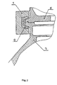
- Figure 2 is a sectional view showing the form in which the system of the invention is applied to the satellite and to the launcher,
- Figure 3 shows, in perspective, a piece of the metal band of the system of the invention, including several jaws,
- Figures 4a and 4b are perspective views which illustrate the metal band of the system of the invention, closed and open respectively, together with the supports intended to retain it on the launcher,
- Figure 5 is a section illustrating the angles of inclination of the inner faces of the jaws,
- Figure 6 is a cross-section of the metal band of the system of the invention, in which the jaw integrated into it has a U-shaped profile, and
- Figure 7 is a cross-section of the metal band of the system of the invention, in which the jaw integrated into it is formed by two independent profiles.
- As can be gathered from the drawings, the system for attaching and separating satellites in accordance with the invention consists of an splitted ring or
metal band 1 which runs round the structures of asatellite 2 and a launcher 3 over the interface which joins them. Thisring 1 can be tensioned by means of a bolt 4 which links two end pieces 5 fixed to the ends of themetal band 1 and which, in order to separate thesatellite 2 from the launcher 3, can be cut by the action of a pyrotechnic charge unit 9. The tension applied to the band orring 1 causes pressure between theinterface hoops satellite 2 and launcher 3 structures, which allows both structures to be kept together as long as pressure exists. - The tension on the
band 1, converted into pressure, is transmitted to thehoops shaped pieces 8 which are found integrated into an inner channel of themetal band 1 in a discontinuous way, that is to say spaced from one another, as has been highlighted in Figure 3, in which the said separated jaws have been designated as 8', this discontinuity making it possible for the said jaws to slide within theband 1, which leads to a uniform distribution of the tension. - As is depicted in the drawings, the
ring 1 has an approximately C- or U-shaped cross-section. Nevertheless, other cross-sections would be possible for the said ring. - Equally, the cross-section of the
jaws 8 can vary so as to conform to the application in each particular case, possibly being, for example, the result of combining the angles of the interface with thesatellite 2 and the launcher 3. On the other hand, thejaws 8 may consist of a continuous profile of approximately U-shaped cross-section, as is illustrated in Figures 2, 3, 5 and 6, or the said jaws can be formed by twoindependent profiles 14 joined together through the base of the channel of thering 1, as is illustrated in Figure 7. - The structure of the launcher 3 is provided with three
supports ring 1 when it opens at the moment when thesatellite 2 is separated from the launcher 3. Thesupport 12 carries aspring 13 which pulls on thering 1 and thus contributes to separating it from the structures (satellite 2 and launcher 3) which have been kept together by means of the said ring until the moment when it opens. - The system of the invention can be applied to satellites of different diameters and can also be subjected to the differing tensions necessary to keep the satellite and its launcher joined together. As an example of a practical embodiment of the system of the invention, a prototype can be cited, constructed for a
satellite 2 of 1.3 m diameter and for a tension in theband 1 of 2.5 MT, in which thering 1 has a width a of 38 mm and a thickness b of 20 mm, the thickness c of the wings of the U-shaped profile of thejaws 8 is 4 mm and the angle γ formed by the inclined faces of the said wings is 30°. - Obviously, the values which have just been given have to be considered as merely illustrative and not limiting, given that, in the final analysis, such values have to be selected by taking the particular conditions of the application into account.
- Equally, the angles α and β illustrated in Figure 5 may, by way of example, take values of 15° and 6°, respectively.
- The operation of the system of the invention proceeds in the following way:
- When a command activates the pyrotechnic charge unit 9 fixed to the tensioning bolt 4, the bolt is cut and hence the
ring 1 moves so as to regain its original shape, opening and finally being retained, that is to say parked, in the three supports 10, 11 and 12 fixed to the structure of the launcher 3, of which the two supports 10, 11 close to the ends of thering 1 prevent the ring from continuing to open, while theopposite support 12 pulls the ring out by means of thespring 13, separating the ring from thestructures 2, 3 retained by it and freeing them from its grip. - The advantage which the system of the invention confers is that of making it possible to withstand higher loadings (and hence to support heavier satellites) than the conventional band systems, by virtue of the extra rigidity provided by the circumferential continuity of the
ring 1. For their part, thejaws 8 operate as an interface element which, on one hand, allows better matching to the manufacturing tolerances of therings 1 and, on the other hand, allows the structural requirements of thering 1 to be decoupled from the requirements for the contact between the said ring and thesatellite 2 and carrier 3 structures. - Likewise, the fact that the system of the invention employs a
continuous metal ring 1 affords an additional advantage in that it allows the mechanical tensioning of the band of the said ring to be replaced by thermal tensioning (banding), it being possible also to combine both forms of tensioning. The thermal tensioning further contributes to the uniformity of the tension applied by themetal band 1. - The above description seeks to bring together what are considered to be the essential characteristics of the present invention. Nevertheless, it is understood that the invention could be modified in various ways without thereby departing from its specific scope, which should be limited only by the content of the claims which follow.
Claims (8)
- System for attaching and separating satellites, designed as a belt or band in order to link two structures (satellite 2 and launcher 3), to keep them together, withstanding the loadings generated during the launch, to separate the upper structure (satellite 2) from the lower structure (launcher 3) when a command activates a pyrotechnic charge unit (9), and, finally, to park the belt or band automatically in a stable position in the launcher (3), characterised in that it comprises an open ring or metal band (1) which has a channel formed in its inner perimeter, in which a series of wedge- or jaw-shaped pieces (8) are integrated in a discontinuous way, which can slide in the said channel and consist of a material which is different from that of the said ring (1); two end pieces (5), each of them fixed to one end of the said ring (1); a bolt (4) which serves to tension the said ring (1) when it is applied to the interface joining the satellite (2) and launcher (3) structures and which joins the two end pieces (5), it being possible for the said bolt (4) to be cut by the action of the said pyrotechnic charge unit (9); and three supports (10, 11, 12) for retaining the ring (1), which are fixed to the structure of the launcher (3), two of which (10, 11) are close to the ends of the ring (1) and the third (12) of which is opposite the opening of the said ring and has a spring (13) which pulls on the ring during its extraction in order to release the satellite (2) from the launcher (3).
- System according to Claim 1, characterised in that the channel formed in the inner face of the metal ring (1) is of variable cross-sectional configuration.
- System according to Claim 2, characterised in that the cross-section of the channel of the metal ring (1) is approximately U- or C-shaped.
- System according to any one of Claims 1 to 3, characterised in that the jaws (8) integrated into the metal ring (1) are of variable cross-sectional configuration.
- System according to Claim 4, characterised in that the configuration of the cross-section of the jaws (8) is the result of combining the angles of the interface of the jaws with the satellite (2) and the launcher (3).
- System according to any one of the preceding claims, characterised in that the jaws (8) consist of a continuous profile of approximately U-shaped cross-section.
- System according to any one of Claims 1 to 5, characterised in that the jaws (8) are formed by two independent profiles (14) joined together through the base of the channel of the ring (1).
- System according to any one of the preceding claims, characterised in that the metal ring (1) is of aluminium or aluminium alloy and the jaws (8) are of plastic, composite or other material with properties appropriate for it to slide in the said ring.
Applications Claiming Priority (2)
| Application Number | Priority Date | Filing Date | Title |
|---|---|---|---|
| ES9702028 | 1997-09-26 | ||
| ES009702028A ES2131476B1 (en) | 1997-09-26 | 1997-09-26 | SATELLITE FIXING AND SEPARATION SYSTEM. |
Publications (2)
| Publication Number | Publication Date |
|---|---|
| EP0905022A1 EP0905022A1 (en) | 1999-03-31 |
| EP0905022B1 true EP0905022B1 (en) | 2003-06-11 |
Family
ID=8300723
Family Applications (1)
| Application Number | Title | Priority Date | Filing Date |
|---|---|---|---|
| EP98500205A Expired - Lifetime EP0905022B1 (en) | 1997-09-26 | 1998-09-18 | System for attaching and separating satellites |
Country Status (8)
| Country | Link |
|---|---|
| US (1) | US6076467A (en) |
| EP (1) | EP0905022B1 (en) |
| JP (1) | JP4159149B2 (en) |
| CN (1) | CN1080229C (en) |
| AT (1) | ATE242716T1 (en) |
| CA (1) | CA2247852C (en) |
| DE (1) | DE69815460T2 (en) |
| ES (1) | ES2131476B1 (en) |
Cited By (1)
| Publication number | Priority date | Publication date | Assignee | Title |
|---|---|---|---|---|
| EP4733202A1 (en) | 2024-10-25 | 2026-04-29 | Occam Space, S.L. | Releasable clamping device for connection and separation of two parts of space vehicles |
Families Citing this family (68)
| Publication number | Priority date | Publication date | Assignee | Title |
|---|---|---|---|---|
| ES2166234B1 (en) * | 1998-11-18 | 2003-02-16 | Eads Constr Aeronauticas Sa | A SYSTEM OF MODIFICATION OF THE PROPERTIES OF RIGIDITY / AMORTIGUATION OF STRUCTURAL UNIONS. |
| SE511762C2 (en) * | 1999-02-03 | 1999-11-22 | Saab Ericsson Space Ab | Spaces by spacecraft |
| WO2001002248A1 (en) * | 1999-07-02 | 2001-01-11 | Saab Ericsson Space Ab | Method and device for the separation of a satellite from a carrier rocket |
| US6454214B1 (en) * | 2000-05-10 | 2002-09-24 | Saab Ericsson Space Ab | Device and method for connecting two parts of a craft |
| KR100385812B1 (en) * | 2000-08-14 | 2003-06-02 | 한국항공우주연구원 | Open Petal Type Rocket Stage Separation System |
| GB2372976B (en) * | 2000-09-18 | 2004-07-07 | Saab Ericsson Space Ab | An Adaptor for a Spacecraft |
| SE0003315L (en) * | 2000-09-18 | 2001-10-15 | Saab Ericsson Space Ab | Device and method for a spacecraft |
| SE0004645L (en) * | 2000-12-14 | 2002-01-29 | Saab Ericsson Space Ab | Bandage on a spacecraft |
| DE10111896B8 (en) * | 2001-03-13 | 2012-06-06 | Eads Space Transportation Gmbh | Metallic ring for the connection of two rotationally symmetrical structural parts |
| US6702300B1 (en) * | 2002-01-11 | 2004-03-09 | The United States Of America As Represented By The Administrator Of The National Aeronautics And Space Administration | High temperature seal for large structural movements |
| KR100515027B1 (en) * | 2002-01-14 | 2005-09-15 | 국방과학연구소 | Band assembly for mounting torpedo |
| FR2839550B1 (en) * | 2002-05-07 | 2004-07-30 | Eads Launch Vehicles | DEVICE FOR PROVISIONAL CONNECTION AND PYROTECHNICAL SEPARATION OF TWO ELEMENTS, WITH MOBILE ORGAN |
| DE10301783B4 (en) * | 2003-01-18 | 2005-04-28 | Eads Space Transp Gmbh | Device for releasably connecting rotationally symmetrical components |
| DE10303377A1 (en) * | 2003-01-29 | 2004-08-05 | Dynamit Nobel Ais Gmbh Automotive Ignition Systems | Pyromechanical separator |
| DE10343627B4 (en) * | 2003-09-20 | 2014-03-06 | Eads Deutschland Gmbh | Closure element for an area of the outer skin of an aircraft |
| US7261038B2 (en) * | 2003-10-24 | 2007-08-28 | The Boeing Company | Low shock separation joint and method therefor |
| US7278612B1 (en) * | 2003-12-05 | 2007-10-09 | Lockheed Martin Corporation | Swaged cable deployment in space |
| US20060145016A1 (en) * | 2004-12-30 | 2006-07-06 | The Boeing Company | Mating of spacecraft components using shape memory materials |
| US7748663B1 (en) * | 2005-05-24 | 2010-07-06 | Lockheed Martin Corporation | Launch vehicle stage integration device |
| ES2372060T3 (en) * | 2005-10-06 | 2012-01-13 | Eads Casa Espacio, S.L. | CONNECTION-SEPARATION DEVICE OF A LAUNCHER VEHICLE AND A SATELLITE. |
| US8720722B2 (en) * | 2005-12-15 | 2014-05-13 | Cornerstone Research Group, Inc. | Venting mechanism for containers |
| US7905453B2 (en) * | 2006-12-21 | 2011-03-15 | Intelsat | Piggyback equipment panel payload arrangement, a device for and method of attaching a hosted secondary piggyback payload and adapter to be used for a piggyback secondary payload arrangement for launching the piggyback equipment panel secondary |
| US7866607B2 (en) * | 2006-12-21 | 2011-01-11 | Intelsat | Piggyback satellite payload arrangement, a device for and method of attaching a piggyback satellite payload and adapter to be used for a piggyback satellite payload arrangement for launching the piggyback satellite |
| US8141491B1 (en) * | 2009-08-18 | 2012-03-27 | Raytheon Company | Expanding tube separation device |
| US8979035B2 (en) * | 2009-11-18 | 2015-03-17 | Ruag Schweiz Ag | Zero-shock separation system |
| US20110204177A1 (en) * | 2010-02-25 | 2011-08-25 | Pacific Scientific Energetic Materials Company | Projectile diverter release and method of diverting a projectile |
| CN101995193B (en) * | 2010-09-03 | 2013-06-19 | 航天东方红卫星有限公司 | Method for separating satellite and rocket separation electric connector by redundancy backup |
| FR2974566B1 (en) * | 2011-04-26 | 2013-12-27 | Astrium Sas | METHOD FOR TEMPORARILY CONNECTING TWO PARTS, SUCH AS TWO STAGES OF A SPATIAL LAUNCHER, AND A SET OF TWO TEMPORARYLY CONNECTED PIECES |
| RU2476816C1 (en) * | 2011-08-30 | 2013-02-27 | Открытое акционерное общество "Военно-промышленная корпорация "Научно-производственное объединение машиностроения" | Unit of joining of detachable rocket stages |
| EP2662289B1 (en) * | 2012-05-09 | 2016-07-13 | RUAG Space AB | Load bearing interface ring for spacecraft |
| CN102767996B (en) * | 2012-07-30 | 2014-08-27 | 上海宇航系统工程研究所 | Low-impact clamp band joint unlocking device |
| CN103335565B (en) * | 2013-06-18 | 2015-11-18 | 上海宇航系统工程研究所 | A kind of band connects tripper |
| CN105339640B (en) | 2013-07-02 | 2018-07-17 | Mra系统有限责任公司 | Engine and band clamp |
| CN103727926B (en) * | 2013-12-19 | 2016-07-27 | 上海卫星工程研究所 | Measuring method based on micro-separating property of high-speed photography |
| KR101558434B1 (en) * | 2013-12-19 | 2015-10-07 | 국방과학연구소 | Weight fixing apparatus of hinge type clamp for launching tube |
| CN103940306B (en) * | 2014-05-14 | 2016-05-11 | 晋西工业集团有限责任公司 | A kind of rocket projectile separating mechanism |
| PL3225558T3 (en) * | 2014-11-25 | 2019-07-31 | Airbus Defence And Space, S.A. | Separation system for separable elements of a spacecraft or launcher |
| US20160347481A1 (en) * | 2014-11-26 | 2016-12-01 | Raytheon Company | Energy Absorbing Restraint Device |
| CN104760709A (en) * | 2015-03-30 | 2015-07-08 | 中国科学院长春光学精密机械与物理研究所 | Wrapping tape type unlocking and separation device driven by explosive bolts |
| WO2017188867A1 (en) * | 2016-04-25 | 2017-11-02 | Ruag Space Ab | Separable roller screw assembly for a space craft release mechanism system |
| EP3478586A4 (en) * | 2016-06-30 | 2020-02-19 | RUAG Space AB | CONNECTING ELEMENT AND CLAMPING TAPE SYSTEM FOR DETACHABLE CONNECTION OF SPACE VEHICLE ELEMENTS |
| CN106742081B (en) * | 2016-11-29 | 2021-02-05 | 航天东方红卫星有限公司 | Separating mechanism based on unlocking of rotary pressure ring |
| EP3560842B1 (en) * | 2016-12-22 | 2020-09-09 | Airbus Defence and Space, S.A. | Connection/separation device for separating satellites from shuttles or from satellite dispensers |
| US10669048B1 (en) * | 2017-06-15 | 2020-06-02 | United Launch Alliance, L.L.C. | Mechanism for increasing jettison clearance |
| CN107954006B (en) * | 2017-11-23 | 2019-12-20 | 北京宇航系统工程研究所 | Rigid belt releasing device |
| US11713142B2 (en) * | 2017-12-01 | 2023-08-01 | Ensign-Bickford Aerospace & Defense Comany | Separation device assemblies |
| CN108050351B (en) * | 2017-12-08 | 2020-01-10 | 中国科学院长春光学精密机械与物理研究所 | Unlocking type space remote sensing camera support |
| CN109823576B (en) * | 2019-02-20 | 2020-11-24 | 上海卫星工程研究所 | Bearing connection structure for planetary lander |
| US10989243B2 (en) * | 2019-03-25 | 2021-04-27 | United States Of America, As Represented By The Secretary Of The Navy | Doubly-separating explosively releasable bolt |
| FR3096033B1 (en) | 2019-05-14 | 2021-05-28 | Spirit Tech | Circumferential coupling system, in particular for coupling a satellite and a planet carrier |
| US11724783B2 (en) * | 2019-07-17 | 2023-08-15 | L3Harris Technologies, Inc. | Bow clamp |
| CN110631432B (en) * | 2019-08-08 | 2020-10-13 | 陕西蓝箭航天技术有限公司 | Liquid rocket pipeline separation device |
| CN111284731B (en) * | 2020-01-16 | 2020-11-10 | 清华大学 | Electromagnetic locking and releasing mechanism for star-rocket separation and electromagnetic locking and releasing method |
| CN111453002B (en) * | 2020-04-13 | 2021-08-17 | 中国科学院力学研究所 | Launch vehicle, pyrotechnic cutting cord protective cover and components thereof |
| CN111619831B (en) * | 2020-04-29 | 2021-11-16 | 航天东方红卫星有限公司 | Connecting rod type satellite-rocket separation mechanism |
| CN112124611B (en) * | 2020-08-22 | 2023-11-28 | 西安科为实业发展有限责任公司 | Shelling separation system and method for cylindrical jet type folding wing aircraft |
| CN112046797B (en) * | 2020-09-11 | 2022-06-24 | 中国空间技术研究院 | capture docking device |
| CN112873117B (en) * | 2021-01-05 | 2022-07-08 | 航天行云科技有限公司 | Multi-satellite separation system installation tool and method |
| RU2760226C1 (en) * | 2021-01-14 | 2021-11-23 | Акционерное общество "Военно-промышленная корпорация "Научно-производственное объединение машиностроения" | Docking unit for electrical circuits of rocket compartments |
| US11852181B1 (en) | 2021-08-30 | 2023-12-26 | United States Of America, As Represented By The Secretary Of The Navy | Separation bolt by eutectic decohesion |
| CN113772135B (en) * | 2021-09-06 | 2024-03-29 | 太原科技大学 | Pneumatic shearing unlocking mechanism and application thereof |
| PL439888A1 (en) | 2021-12-17 | 2023-06-19 | Sieć Badawcza Łukasiewicz - Instytut Lotnictwa | Module separation mechanism, especially for rockets |
| CN115009540B (en) * | 2022-06-02 | 2025-07-04 | 南京航空航天大学 | A wall-mounted pico-satellite annular unlocking device |
| CN115009549B (en) * | 2022-08-09 | 2022-11-18 | 北京星河动力装备科技有限公司 | Locking and releasing mechanism, control method thereof and carrier rocket |
| CN116039971B (en) * | 2023-02-23 | 2025-07-15 | 东方空间技术(山东)有限公司 | A rocket secondary binding mechanism |
| DE102024001419A1 (en) * | 2024-05-02 | 2025-11-06 | Mbda Deutschland Gmbh | Aerospace device with a propulsion stage connection having a separation mechanism and method for controlled separation of propulsion stages of an aerospace device |
| EP4714834A1 (en) * | 2024-09-20 | 2026-03-25 | EXOLAUNCH GmbH | Device for releasable attachment of payloads to a spacecraft |
| CN120991668A (en) * | 2025-08-26 | 2025-11-21 | 河南天章火箭有限公司 | An air conditioning vent cover, connector, and connection system for a launch vehicle fairing |
Family Cites Families (30)
| Publication number | Priority date | Publication date | Assignee | Title |
|---|---|---|---|---|
| US3196635A (en) * | 1963-01-07 | 1965-07-27 | Falk Corp | Coupling |
| US3244104A (en) * | 1964-03-25 | 1966-04-05 | Jimmie R Mills | Missile separating device |
| GB1077581A (en) * | 1964-06-05 | 1967-08-02 | British Aircraft Corp Ltd | Separation of a satellite from a launcher |
| US3346929A (en) * | 1966-03-04 | 1967-10-17 | James E Webb | Latching mechanism |
| US3458217A (en) * | 1966-11-25 | 1969-07-29 | Joseph D Pride Jr | Tubular coupling having low profile band segments with means for preventing relative rotation |
| US3438303A (en) * | 1966-11-30 | 1969-04-15 | Bombrini Parodi Delfino Spa | System including a tubular launching tube and a rocket provided with an outer auxiliary launching charge |
| US3501112A (en) * | 1967-09-15 | 1970-03-17 | Nasa | Sealed separable connection |
| US3505925A (en) * | 1967-10-16 | 1970-04-14 | Mc Donnell Douglas Corp | Structure release system |
| GB1220994A (en) * | 1968-03-07 | 1971-01-27 | Trw Inc | Band retainer for satellite separation system |
| DE1922730A1 (en) * | 1969-05-03 | 1971-02-04 | Dynamit Nobel Ag | Container ejection cartridges for rocket/ - plane etc |
| US3633456A (en) * | 1969-07-03 | 1972-01-11 | Mc Donnell Douglas Corp | Power-actuated separation system |
| US3564564A (en) * | 1969-11-21 | 1971-02-16 | Nasa | Latching mechanism |
| DE2062087A1 (en) * | 1970-12-17 | 1972-07-06 | Hahn, Hans, Dr.-Ing., 2000 Hamburg | Fuse attachment - esp for rocket by using soft open-pored polyurethane impregnated with viscous hardening plastic |
| US3737117A (en) * | 1971-07-06 | 1973-06-05 | Nasa | Docking structure for spacecraft |
| FR2516893A1 (en) * | 1981-11-26 | 1983-05-27 | Aerospatiale | SYSTEM FOR THE TEMPORARY MAINTENANCE AND RELEASE OF TWO PARTS, ESPECIALLY IN THE SPATIAL FIELD |
| FR2565302B1 (en) * | 1984-06-05 | 1986-10-10 | Aerospatiale | PROVISIONAL SECURITY DEVICE IN THE SPACE OF TWO PIECES EDGE TO EDGE |
| US4627355A (en) * | 1984-06-19 | 1986-12-09 | Westinghouse Electric Corp. | Joint release mechanism |
| US4715565A (en) * | 1986-05-27 | 1987-12-29 | Hughes Aircraft Company | Clamping connection assembly for spacecraft |
| SU1740970A1 (en) * | 1990-01-22 | 1992-06-15 | Головное конструкторское бюро Научно-производственного объединения "Энергия" | Electric communication center for separable parts of missiles |
| FR2665951B1 (en) * | 1990-08-20 | 1992-11-13 | Aerospatiale | BREAKABLE CONNECTION SYSTEM FOR SEPARATING PARTS BY MEANS OF A DETONATING LOAD. |
| DE4038780A1 (en) * | 1990-12-05 | 1992-06-11 | Mauser Werke Oberndorf | Missile with detachable propulsion plug - has connecting body between detached by relative movement in axial direction, detaching body from plug whilst in barrel of gun |
| FR2670844B1 (en) * | 1990-12-21 | 1993-04-16 | Aerospatiale | REMOTE RELEASE TENSIONING MECHANISM OF A FLEXIBLE MEMBER SUCH AS A STRAP AND DEVICE FOR RIGID CONNECTION OF TWO MECHANICAL ASSEMBLIES USING SUCH A MECHANISM. |
| US5314144A (en) * | 1991-12-18 | 1994-05-24 | Raytheon Company | Thermally compensating insert fastener |
| DE4221525C2 (en) * | 1992-07-01 | 1996-08-08 | Daimler Benz Aerospace Ag | Device for connecting cylindrical components |
| US5390606A (en) * | 1992-11-02 | 1995-02-21 | Orbital Sciences Corporation | Frangible joint separation system |
| US5352061A (en) * | 1993-01-05 | 1994-10-04 | Honeywell Inc. | Anti-rotation ring joint |
| SE509256C2 (en) * | 1994-06-14 | 1998-12-21 | Saab Ericsson Space Ab | Bandage for detachable connection of adapter on carrier rocket with satellite |
| FR2735099B1 (en) * | 1995-06-06 | 1997-08-29 | Aerospatiale | TILTING ADAPTER DEVICE FOR CARRYING MULTIPLE USEFUL LOADS ON THE SAME LAUNCHER. |
| ES2120338B1 (en) * | 1995-10-16 | 1999-05-01 | Const Aeronauticas Sa | FIXING AND SEPARATION SYSTEM FOR SATELLITES. |
| US5898123A (en) * | 1997-05-01 | 1999-04-27 | The Ensign-Bickford Company | Sealing device and a method for assembly thereof |
-
1997
- 1997-09-26 ES ES009702028A patent/ES2131476B1/en not_active Expired - Fee Related
-
1998
- 1998-06-18 US US09/099,493 patent/US6076467A/en not_active Expired - Lifetime
- 1998-09-18 DE DE69815460T patent/DE69815460T2/en not_active Expired - Lifetime
- 1998-09-18 EP EP98500205A patent/EP0905022B1/en not_active Expired - Lifetime
- 1998-09-18 AT AT98500205T patent/ATE242716T1/en not_active IP Right Cessation
- 1998-09-22 CN CN98119860A patent/CN1080229C/en not_active Expired - Fee Related
- 1998-09-25 JP JP27191598A patent/JP4159149B2/en not_active Expired - Fee Related
- 1998-09-25 CA CA002247852A patent/CA2247852C/en not_active Expired - Lifetime
Cited By (2)
| Publication number | Priority date | Publication date | Assignee | Title |
|---|---|---|---|---|
| EP4733202A1 (en) | 2024-10-25 | 2026-04-29 | Occam Space, S.L. | Releasable clamping device for connection and separation of two parts of space vehicles |
| WO2026087710A1 (en) | 2024-10-25 | 2026-04-30 | Occam Space, S.L. | Releasable clamping device for connection and separation of two parts of space vehicles |
Also Published As
| Publication number | Publication date |
|---|---|
| ATE242716T1 (en) | 2003-06-15 |
| ES2131476B1 (en) | 2000-03-01 |
| ES2131476A1 (en) | 1999-07-16 |
| CA2247852C (en) | 2007-05-15 |
| CN1080229C (en) | 2002-03-06 |
| JP4159149B2 (en) | 2008-10-01 |
| JPH11152100A (en) | 1999-06-08 |
| DE69815460D1 (en) | 2003-07-17 |
| DE69815460T2 (en) | 2004-05-06 |
| US6076467A (en) | 2000-06-20 |
| EP0905022A1 (en) | 1999-03-31 |
| CN1212940A (en) | 1999-04-07 |
| CA2247852A1 (en) | 1999-03-26 |
Similar Documents
| Publication | Publication Date | Title |
|---|---|---|
| EP0905022A1 (en) | System for attaching and separating satellites | |
| EP3560842A1 (en) | Connection/separation device for separating satellites from shuttles or from satellite dispensers | |
| EP1202905B1 (en) | Reusable, separable, structural connector assembly and method for connecting two vehicles | |
| EP1543290B1 (en) | Apparatus and method for releaseably joining elements | |
| CN101326102B (en) | Launch Vehicle and Satellite Link Separation Equipment | |
| US20170341782A1 (en) | System for separating separable spacecraft and shuttle elements | |
| US6290182B1 (en) | Joint for space vehicle | |
| EP3553331B1 (en) | Device for pivoting connection between at least two parts, aircraft comprising a cowl equipped with said pivoting connection device | |
| FR2518483A1 (en) | GAS SPRING ASSEMBLY FOR A MOTOR VEHICLE | |
| US4306740A (en) | Hose clamp structure and hose construction employing same | |
| JP2532923B2 (en) | Device for joining cylindrical components | |
| US5735626A (en) | Separating rail assembly | |
| FR2839550A1 (en) | DEVICE FOR PROVISIONAL CONNECTION AND PYROTECHNICAL SEPARATION OF TWO ELEMENTS, WITH MOBILE ORGAN | |
| US6712542B2 (en) | Apparatus and method for altering the tension of a clampband | |
| JPH01237295A (en) | Device for temporarily locking rotor to stator | |
| JPH0717499A (en) | Device for connecting cylindrical components | |
| EP0768241A1 (en) | Fastening and separating system for satellites | |
| EP0030498B1 (en) | Self separating pyrotechnic connector having sealed parts | |
| EP0211454A1 (en) | Process and device for effecting a gas-tight joint and joint so produced | |
| EP0079622A2 (en) | Apparatus for assembling container halves | |
| FR2488393A1 (en) | COMBAT CONE FOR DISPERSION WEAPON | |
| JP2000055600A (en) | Flying object payload separation device | |
| FR2562654A1 (en) | SAFETY DEVICE FOR PREVENTING THE ARMING OF AN AIRBORNE LOAD | |
| FR2916182A3 (en) | ARRANGEMENT FOR HOLDING IN POSITION OF MOUNTING A SUSPENDED TURBOCHARGER. | |
| WEN | The Ariane 5 Launch and Operation Facilities |
Legal Events
| Date | Code | Title | Description |
|---|---|---|---|
| PUAI | Public reference made under article 153(3) epc to a published international application that has entered the european phase |
Free format text: ORIGINAL CODE: 0009012 |
|
| AK | Designated contracting states |
Kind code of ref document: A1 Designated state(s): AT BE CH DE DK ES FI FR GB GR IE IT LI LU MC NL PT SE |
|
| AX | Request for extension of the european patent |
Free format text: AL;LT;LV;MK;RO;SI |
|
| 17P | Request for examination filed |
Effective date: 19990903 |
|
| AKX | Designation fees paid |
Free format text: AT BE CH DE DK ES FI FR GB GR IE IT LI LU MC NL PT SE |
|
| GRAH | Despatch of communication of intention to grant a patent |
Free format text: ORIGINAL CODE: EPIDOS IGRA |
|
| GRAA | (expected) grant |
Free format text: ORIGINAL CODE: 0009210 |
|
| GRAH | Despatch of communication of intention to grant a patent |
Free format text: ORIGINAL CODE: EPIDOS IGRA |
|
| AK | Designated contracting states |
Designated state(s): AT BE CH DE DK ES FI FR GB GR IE IT LI LU MC NL PT SE |
|
| PG25 | Lapsed in a contracting state [announced via postgrant information from national office to epo] |
Ref country code: NL Free format text: LAPSE BECAUSE OF FAILURE TO SUBMIT A TRANSLATION OF THE DESCRIPTION OR TO PAY THE FEE WITHIN THE PRESCRIBED TIME-LIMIT Effective date: 20030611 Ref country code: LI Free format text: LAPSE BECAUSE OF FAILURE TO SUBMIT A TRANSLATION OF THE DESCRIPTION OR TO PAY THE FEE WITHIN THE PRESCRIBED TIME-LIMIT Effective date: 20030611 Ref country code: FI Free format text: LAPSE BECAUSE OF FAILURE TO SUBMIT A TRANSLATION OF THE DESCRIPTION OR TO PAY THE FEE WITHIN THE PRESCRIBED TIME-LIMIT Effective date: 20030611 Ref country code: CH Free format text: LAPSE BECAUSE OF FAILURE TO SUBMIT A TRANSLATION OF THE DESCRIPTION OR TO PAY THE FEE WITHIN THE PRESCRIBED TIME-LIMIT Effective date: 20030611 Ref country code: BE Free format text: LAPSE BECAUSE OF FAILURE TO SUBMIT A TRANSLATION OF THE DESCRIPTION OR TO PAY THE FEE WITHIN THE PRESCRIBED TIME-LIMIT Effective date: 20030611 Ref country code: AT Free format text: LAPSE BECAUSE OF FAILURE TO SUBMIT A TRANSLATION OF THE DESCRIPTION OR TO PAY THE FEE WITHIN THE PRESCRIBED TIME-LIMIT Effective date: 20030611 |
|
| REG | Reference to a national code |
Ref country code: GB Ref legal event code: FG4D |
|
| REG | Reference to a national code |
Ref country code: CH Ref legal event code: EP |
|
| REG | Reference to a national code |
Ref country code: IE Ref legal event code: FG4D |
|
| REF | Corresponds to: |
Ref document number: 69815460 Country of ref document: DE Date of ref document: 20030717 Kind code of ref document: P |
|
| PG25 | Lapsed in a contracting state [announced via postgrant information from national office to epo] |
Ref country code: PT Free format text: LAPSE BECAUSE OF FAILURE TO SUBMIT A TRANSLATION OF THE DESCRIPTION OR TO PAY THE FEE WITHIN THE PRESCRIBED TIME-LIMIT Effective date: 20030911 Ref country code: GR Free format text: LAPSE BECAUSE OF FAILURE TO SUBMIT A TRANSLATION OF THE DESCRIPTION OR TO PAY THE FEE WITHIN THE PRESCRIBED TIME-LIMIT Effective date: 20030911 Ref country code: DK Free format text: LAPSE BECAUSE OF FAILURE TO SUBMIT A TRANSLATION OF THE DESCRIPTION OR TO PAY THE FEE WITHIN THE PRESCRIBED TIME-LIMIT Effective date: 20030911 |
|
| PG25 | Lapsed in a contracting state [announced via postgrant information from national office to epo] |
Ref country code: LU Free format text: LAPSE BECAUSE OF NON-PAYMENT OF DUE FEES Effective date: 20030918 Ref country code: IE Free format text: LAPSE BECAUSE OF NON-PAYMENT OF DUE FEES Effective date: 20030918 |
|
| PG25 | Lapsed in a contracting state [announced via postgrant information from national office to epo] |
Ref country code: ES Free format text: LAPSE BECAUSE OF FAILURE TO SUBMIT A TRANSLATION OF THE DESCRIPTION OR TO PAY THE FEE WITHIN THE PRESCRIBED TIME-LIMIT Effective date: 20030922 |
|
| PG25 | Lapsed in a contracting state [announced via postgrant information from national office to epo] |
Ref country code: MC Free format text: LAPSE BECAUSE OF NON-PAYMENT OF DUE FEES Effective date: 20030930 |
|
| REG | Reference to a national code |
Ref country code: SE Ref legal event code: TRGR |
|
| NLV1 | Nl: lapsed or annulled due to failure to fulfill the requirements of art. 29p and 29m of the patents act | ||
| REG | Reference to a national code |
Ref country code: CH Ref legal event code: PL |
|
| RAP2 | Party data changed (patent owner data changed or rights of a patent transferred) |
Owner name: EADS CONSTRUCCIONES AERONAUTICAS S.A. |
|
| PLBE | No opposition filed within time limit |
Free format text: ORIGINAL CODE: 0009261 |
|
| STAA | Information on the status of an ep patent application or granted ep patent |
Free format text: STATUS: NO OPPOSITION FILED WITHIN TIME LIMIT |
|
| RAP2 | Party data changed (patent owner data changed or rights of a patent transferred) |
Owner name: EADS CASA ESPACIO, S.L. |
|
| ET | Fr: translation filed | ||
| 26N | No opposition filed |
Effective date: 20040312 |
|
| REG | Reference to a national code |
Ref country code: IE Ref legal event code: MM4A |
|
| REG | Reference to a national code |
Ref country code: GB Ref legal event code: 732E |
|
| PGFP | Annual fee paid to national office [announced via postgrant information from national office to epo] |
Ref country code: GB Payment date: 20120912 Year of fee payment: 15 |
|
| PGFP | Annual fee paid to national office [announced via postgrant information from national office to epo] |
Ref country code: IT Payment date: 20120927 Year of fee payment: 15 |
|
| GBPC | Gb: european patent ceased through non-payment of renewal fee |
Effective date: 20130918 |
|
| PG25 | Lapsed in a contracting state [announced via postgrant information from national office to epo] |
Ref country code: GB Free format text: LAPSE BECAUSE OF NON-PAYMENT OF DUE FEES Effective date: 20130918 |
|
| PG25 | Lapsed in a contracting state [announced via postgrant information from national office to epo] |
Ref country code: IT Free format text: LAPSE BECAUSE OF NON-PAYMENT OF DUE FEES Effective date: 20130918 |
|
| REG | Reference to a national code |
Ref country code: FR Ref legal event code: PLFP Year of fee payment: 19 |
|
| REG | Reference to a national code |
Ref country code: FR Ref legal event code: PLFP Year of fee payment: 20 |
|
| PGFP | Annual fee paid to national office [announced via postgrant information from national office to epo] |
Ref country code: FR Payment date: 20170928 Year of fee payment: 20 Ref country code: DE Payment date: 20170928 Year of fee payment: 20 |
|
| PGFP | Annual fee paid to national office [announced via postgrant information from national office to epo] |
Ref country code: SE Payment date: 20170921 Year of fee payment: 20 |
|
| REG | Reference to a national code |
Ref country code: DE Ref legal event code: R071 Ref document number: 69815460 Country of ref document: DE |