EP0904949A1 - Method and device for controlling printing density in a stencil printing machine - Google Patents
Method and device for controlling printing density in a stencil printing machine Download PDFInfo
- Publication number
- EP0904949A1 EP0904949A1 EP98307964A EP98307964A EP0904949A1 EP 0904949 A1 EP0904949 A1 EP 0904949A1 EP 98307964 A EP98307964 A EP 98307964A EP 98307964 A EP98307964 A EP 98307964A EP 0904949 A1 EP0904949 A1 EP 0904949A1
- Authority
- EP
- European Patent Office
- Prior art keywords
- printing
- value
- drum
- sheet
- density
- Prior art date
- Legal status (The legal status is an assumption and is not a legal conclusion. Google has not performed a legal analysis and makes no representation as to the accuracy of the status listed.)
- Granted
Links
Images

Classifications
-
- B—PERFORMING OPERATIONS; TRANSPORTING
- B41—PRINTING; LINING MACHINES; TYPEWRITERS; STAMPS
- B41L—APPARATUS OR DEVICES FOR MANIFOLDING, DUPLICATING OR PRINTING FOR OFFICE OR OTHER COMMERCIAL PURPOSES; ADDRESSING MACHINES OR LIKE SERIES-PRINTING MACHINES
- B41L13/00—Stencilling apparatus for office or other commercial use
- B41L13/18—Inking units
Definitions
- the present invention relates to a method for controlling printing density in stencil printing, which is capable of easily controlling the printing density, and to a device for the same.
- a stencil printing device in which a perforated stencil sheet is wound around a circumferential surface of a printing drum with an ink supplied thereto, and in which the ink is transferred from the printing drum to a printing sheet through the perforated stencil sheet by pressing the printing sheet to the printing drum while the drum is rotated.
- Japanese patent publication (Kokai) No. 06-155880 has already proposed a method for implementing stencil printing at a desired density irrespective of the change in printing speed.
- This method comprises variably setting a pressing force applied to the printing sheet against the printing drum, in accordance with printing speed information given by a means for setting printing speed information, for instance, a printing speed set up key provided on an operation panel.
- an object of the present invention is to provide a method and an apparatus for controlling printing density in stencil printing, which are capable of widely and finely varying the printing density at a desired printing speed.
- the quantity of printed ink depends on a value of ⁇ (F/f) (where F is a pressing force at which a printing sheet is pressed to a printing drum, and fis a rotation speed of the drum), and more particularly, that the quantity is approximately proportional to the value of ⁇ (F/f). This means that, even if rotation speed of the drum is varied, the same printing density can be obtained by performing stencil printing at a pressing force which yields the same value of ⁇ (F/f).
- the degree of pressing force that compensates for a change of printing speed to obtain the same printing density has to be determined only by experience.
- a printing speed and a pressing force can be readily set by selecting a value of ⁇ (F/f) as an index of printing density. Therefore, whether printing is put to trial at a low printing speed or into practice at a high printing speed, or even when printing speed is changed during printing, a printer can be controlled so that copies with a constant printing density are provided independently of printing speed.
- the present method for controlling a printing density in stencil printing may comprise a first step of selecting a specific value of D from said predetermined range in order to set a desired printing density, a second step of calculating a possible range of f at the selected value of D and selecting a specific value of f from the calculated range in order to set a desired printing speed, and a third step of calculating a pressing force of F at the selected values of D and f in order to set a pressing force.
- said second step may comprise a step of calculating a possible range of f at the selected value of D and indicating the calculated range off, and a step of selecting a specific value of f from the indicated range in order to set a desired printing speed.
- the present method for controlling a printing density in stencil printing may comprise a first step of selecting a specific value of fin order to set a desired printing speed, a second step of calculating a possible range of D at the selected value of f and selecting a specific value of D from the calculated range in order to set a desired printing density, and a third step of calculating a pressing force of F at the selected values of D and f in order to set a pressing force.
- said second step may comprise a step of calculating a possible range of D at the selected value of f and indicating the calculated range of D, and a step of selecting a specific value of D from the indicated range in order to set a desired printing density.
- the value of F may be monitored to regulate the value of f to keep the variation of the value of D within ⁇ 0.05 (kg ⁇ f/rpm), whereby the rotation speed of drum is controlled.
- the value of f may be monitored to regulate the value of F to keep the variation of the value of D within ⁇ 10.05 (kg ⁇ f/rpm), whereby the pressing force is controlled.
- the printing density controlling device may comprise a printing density setting means for setting a specific value of D within said predetermined range, a printing speed setting means for calculating a possible range of f at the above-set value of D and setting a specific value of f within the calculated range, and a pressing force regulating means for calculating a value of F at the above-set values of D and f and setting the pressing force to the calculated value of F.
- the printing speed setting means may comprise an indication means which calculates a possible range of f at the above-set value of D and indicates the range off, and a speed selecting means which allows a specific value of f to be selected from the indicated range to set a desired printing speed.
- the printing density controlling device may comprise a printing speed setting means for setting a specific value of f to set a desired printing speed, a printing density setting means for calculating a possible range of D at the above-set value of f and setting a specific value of D within the calculated range to set a desired printing density, and a pressing force regulating means for calculating a value of F at the above-set values of D and f and setting the pressing force to the calculated value of F.
- the printing density setting means may comprise an indication means which calculates a possible range of D at the above-set value of f and indicates the range of D, and a printing density selecting means which allows a specific value of D to be selected from the indicated range to set a desired printing density.
- the program may comprise the steps of storing a selected value of D, calculating a possible range of f at the stored value of D, storing a value of f selected from the range of f, and calculating a value of F at the stored values of D and f for setting a pressing force.
- the program may comprise the steps of storing a selected value of D, calculating a possible range of f at the stored value of D and indicating the range of f for selection, storing a value of f selected from the indicated range of f, and calculating a value of F at the stored values of D and f for setting a pressing force.
- the program may comprise the steps of storing a selected value of f, calculating a possible range of D at the stored value off, storing a value of D selected from the range of D, and calculating a value of F at the stored values of f and D for setting a pressing force.
- the program may comprise the steps of storing a selected value of f, calculating a possible range of D at the stored value of f and indicating the range of D for selection, storing a value of D selected from the indicated range of D, and calculating a value of F at the stored values of f and D for setting a pressing force.
- D' a ⁇ (F/f) + b (where a and b are each an arbitrary constant).
- selecting a value of D' means selecting a value of D.
- the rotation speed f (rpm) of the printing drum is, in general, equivalent to a frequency per minute of repeated pressing of an arbitrarily fixed point of the printable outer circumferential surface of the printing drum.
- the rotation speed f(rpm) is equivalent to the number of copies finished in one minute.
- the rotation speed of the drum does not necessarily agree with the printing speed, namely the number of copies finished in one minute.
- rotation speed f (rpm) of the drum meant by the present invention is derived from a surface speed of the drum at a fixed point, which can be converted into a rotation speed f (rpm).
- FIG. 1 shows a preferred embodiment of the stencil printing device according to the present invention, which is equipped with a plate making function.
- This stencil printing device comprises an original reading unit 11, a plate making unit 13, and a printing unit 15.
- the original reading unit 11 essentially consists of an image scanner, and comprises a line image sensor 17 for reading an original image of an original sheet conveyed in a secondary scanning direction, and an original sheet feeding roller 19.
- the plate making unit 13 comprises a stencil sheet roll unit 21, a thermal printing head 2 3 consisting of a plurality of dot-like heat generating elements arranged in a lateral row, master plate sheet feeding rollers 25 and 2 7, master plate sheet guide rollers 29, 31 and 33, and a master plate sheet cutter 35.
- the dot-like heat generating elements in the thermal printing head 23 are selectively activated so that a desired thermal perforation may be carried out on the master plate sheet M, which is heat sensitive, as a plate making process, and the master plate sheet cutter 35 cuts the stencil master plate sheet M after the latter is processed into a master plate.
- the printing unit 15 comprises a cylindrical printing drum 37 made of a perforated metal plate, a mesh structure or an otherwise ink permeable porous structure, an ink supplying unit 39 essentially consisting of a squeegee roller 38 and a doctor roller 40 disposed inside the printing drum 37, and a press roller 41, and the stencil master plate sheet M after being processed into a master plate is mounted on the outer circumferential surface of the printing drum 37.
- a paper feeding unit 43 On one side of the printing unit 15 is provided a paper feeding unit 43, and on the other side of the printing unit 15 is provided a paper ejecting unit 45.
- the paper feeding unit 43 comprises a paper feeding table 47 on which a stack of printing paper P is placed, pick up rollers 49 for picking up the printing paper P on the paper feeding table 47 sheet by sheet, and timing rollers 51 for delivering the printing paper P to the nip between the printing drum 3 7 and the press roller 41.
- the paper ejecting unit 45 comprises a peeling claw 53 for removing the printing paper from the printing drum 37, an ejected paper feeding belt 55, and an ejected paper table 57 for stacking up the printed printing paper.
- a master plate ejecting unit 63 comprising master plate ejecting rollers 61 for peeling off the used stencil master plate sheet M from the printing drum 37 and delivering it into an ejected master plate box 59.
- printing ink of a desired color is supplied by the ink supplying unit 39 into the inner surface of the printing drum 37 while the printing drum 37 is rotated counter clockwise in the drawing around its central axial line by rotative drive means not shown in the drawings.
- Printing paper P is delivered to the nip between the press roller 41 and the printing drum 37 after being fed by the paper feed timing rollers 51 from the left to right in synchronism with the rotation of the printing drum 37 at an appropriate timing.
- the printing paper P is thus pressed upon the printing drum 37 by the press roller 41 onto the stencil master plate sheet M mounted on the outer circumferential surface of the printing drum, and a stencil printing is carried out on the printing paper P by using the printing ink of the desired color.
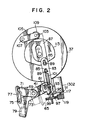
- FIG. 2 shows the drive unit for the press roller 41.
- the press roller 41 is supported by a bracket 65, extending in the axial direction of the printing drum 37, so as to be rotatable around its central axial line, and the bracket 65 is in turn fixedly secured to a press shaft 69 rotatably supported by a fixed member or frame not show in the drawings.
- the press roller 41 is vertically rotatable around the press shaft 69, and can move between a retracted position spaced from the outer circumferential surface of the printing drum 37 and a position for pressing action engaged upon the outer circumferential surface of the printing drum 37.
- the press shaft 69 carries a press drive lever 71 fixedly mounted thereof, and rotatably supports a press drive plate 73.
- a hook member 77 is pivotally supported on the press drive plate 73 by means of a pivot shaft 75, and selectively engages with the press drive lever 71 by being rotatively driven by a solenoid 79 mounted on the press drive plate 73 for selectively engaging the press drive lever 71 with the press drive plate 73.
- first link member 83 An end of a first link member 83 is pivotally connected to an end of the press drive plate 73 by means of a pivot shaft 81.
- the first link member 83 is provided with a pair of slots 85 extending in the same direction, and these slots 85 receive pins 89 of a second link member 87.
- the first link member 83 and the second link member 87 are connected with each other so as to be relatively moveable in the lengthwise direction or vertically as seen in FIG. 2 within the range permitted by the slots 85.
- the lower end of the first link member 83 is provided with a bent flange piece 91 through which an adjust screw 93 is passed so as to be adjustable in the direction of the reciprocating movement of the first link member 83.
- the adjust screw 93 threads with a nut member 99 provided with outer teeth 97 in the manner of a spur gear and supported by the lower surface of the bent flange piece 91 by way of a collar 95 against a thrust force, and the upper end of the adjust screw 93 is connected to an end of a tensile coil spring 101.
- the adjust screw 93 is thus prevented from rotating by being engaged by the one end of the tensile coil spring 101, and is axially displaced with respect to the first link member 83 by the rotation of the nut member 99.
- the tensile coil spring 101 is engaged by one of the pins 89 at its other end, thus urging the first link member 83 upwards relative to the second link member 8 7, or in other words urging the press drive plate 73 in counter clockwise direction in FIG.2 around the press shaft 69 to press the press roller 41 onto the outer circumferential surface of the printing drum 37.
- the second link member 87 is pivotally connected to a free end portion of a cam lever 105 by a pivot shaft 103.
- the cam lever 105 is rotatably supported on a frame not shown in the drawings by a support shaft 107.
- the cam lever 105 rotatably supports a cam follower roller 109 in a freely rotatable manner.
- the cam follower roller 109 engages with a press cam 113 mounted on a main shaft 111.
- the main shaft 111 is rotatably supported by a frame not shown in the drawings.
- the press cam 113 rotates in synchronism with the printing drum 3 7, and is provided with a cam profile which moves the press roller 41 to its retracted position to avoid the interference between the press roller 41 and a clamp unit when the clamp unit is located in a position corresponding to the press roller 41.
- the clamp unit is not shown in the drawings, but disposed on an outer circumferential surface of the printing drum 37 to clamp an end of a stencil master plate sheet wound around the drum as in conventional stencil printing machines.
- the bent flange piece 91 carries an electric motor 1302 for adjusting the pressing force, and a drive gear 119 is fixedly secured to an output shaft 117 of the electric motor.
- the drive gear 119 meshes with the outer teeth 97 of the nut member 99 for transmitting the rotation of the output shaft 117 of the electric motor 1302 for adjusting the pressing force.
- the rotation of the printing drum 37 causes the press cam 113 to rotate in the clockwise direction as seen in FIG. 2, and this rotation in turn causes a substantially vertical reciprocating movement of the second link member 87 which is transmitted to the first link member 83 via the tensile coil spring 101.
- the reciprocating movement of the first link member 83 causes the press drive plate 73 to angularly reciprocate around the press shaft 69, and because the hook member 77 is moved into engagement with the press drive lever 71 by the solenoid 79, the reciprocating movement of the press drive plate 73 is transmitted to the press shaft 69.
- the reciprocating angular movement of the press shaft 69 causes the press roller 41 to vertically rotate around the press shaft 69 so that the press roller 41 may move between the retracted position spaced from the outer circumferential surface of the printing drum 37 and the pressing position where the roller 41 is pressed against the outer circumferential surface of the printing drum 37.
- the movement of the press roller 41 to the pressing position is effected by the second link member 87 being lifted, by this movement being transmitted to the first link member 83 through tensioning of the tensile coil spring 101, and by the press drive plate 73 being rotated in counter clockwise direction as seen in FIG. 2 around the press shaft 69 of the press drive plate 73.
- the press roller 41 is pressed against the outer circumferential surface of the printing drum 37 with the printing paper P interposed therebetween, thereby restricting any further rotation of the press drive plate 73 in counter clockwise direction as seen in FIG. 2 around the press shaft 69.
- the second link member 87 is further lifted until the second link member 87 moves relative to the first link member 83 and the tensile coil spring 101 is extended.
- the spring force of the stretched tensile coil spring 101 presses the press roller 41 on the outer circumferential surface of the printing drum 37 with printing paper P interposed therebetween, and the magnitude of the pressing force is determined by this spring force.
- the electric motor 1302 for the adjustment of the pressing force is activated, and the drive gear 119 is rotated.
- the rotation of the driver gear 119 is transmitted to the nut member 99, and the rotation of the nut member 99 causes the adjust screw 93 to move axially relative to the first link member 8 3, thereby changing the position of the adjust screw 93 relative to the first link member 83.
- the point of engagement between the tensile coil spring 101 and the adjust screw 93 moves axially relative to the first link member 83, and this displacement causes a change in the length of the tensile coil spring 101, and hence its preset spring force.
- the change in the preset force of the tensile coil spring 101 changes the pressure, that is, the pressing force by which the press roller 41 is pressed against the outer circumferential surface of the printing drum 37 as described above. It can be clearly understood that such a means as a solenoid, an air cylinder and a hydraulic pressure is also usable as a means for generating the pressing force.
- the printing drum 37 for use in the present embodiment is supported on a movable support frame as a unit together with an ink bottle accommodating printing ink therein, an ink delivery pump for drawing printing ink from the ink bottle and delivering it to the supplying unit 39, and a drive motor for the ink delivery pump.
- the entire unit can be replaceably loaded into the body of the stencil printing device.
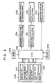
- FIG. 3 shows the control unit which totally controls the operation of the stencil printing device inclusive of the operation control of the electric motor 1302 for the adjustment of the pressing force, in which only the parts of the stencil printing device which are related to the present invention are illustrated for the simplification of description.
- the control unit of FIG. 3 comprises a CPU 1201 consisting of a micro processor or something like that, a ROM 1202 storing programs for controlling the operation of various units in the stencil printing device, and a RAM 1203 storing, as required, results of arithmetic operations carried out by the micro processor and various input information.
- the stencil printing device comprises an operation panel 1100 equipped with a ten key pad 1101 for setting the desired number of copies, a printing speed set up key 1102, a printing density set up key 1103, a printing start key 1104, and a display panel 1105, and the CPU 1201 receives, for instance, information on the desired number of copies set up on the ten key pad 1101; information on printing speed set up by the printing speed set up key 1102, that is, information on rotation speed of the printing drum; information on a relative printing density set by the printing density set up key 1103, that is, information on a value of ⁇ (F/f); and information commanding a start of printing set by the printing start key 1104.
- the CPU 1201 controls the drive motor 1312 for the printing drum via the motor drive circuit 1311 for driving the printing drum, and receives information on an actual rotation speed of the printing drum fed back from a rotation speed sensor 1313 for the printing drum.
- the CPU 1201 determines a pressing force in performing printing based on the set value of ⁇ (F/f) and the rotation speed of the printing drum, either by calculation or with reference to a table in which previously-calculated results are stored.
- the CPU 1201 also determines an operation quantity of the motor 1302 for adjustment to a targeted pressing force, and outputs the operation quantity to the motor drive circuit 1301. Furthermore, when rotation speed of the printing drum is accelerated or decelerated during printing, the motor 1302 for the adjustment of the pressing force is controlled to increase or decrease the pressing force to maintain the previously set value of ⁇ (F/f) to be substantially constant.
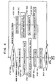
- a control flow for adjustment operation of printing density for the stencil printing device according to the present invention is shown in FIG. 4 and FIG. 5.
- a printing mode is first selected to give priority to either density or speed (step 100).
- a desired printing density is set by the printing density set up key 1103 on the operation panel 1100.
- the printing density maybe set by direct input of a value of ⁇ (F/f) by the ten key pad or the like, or may be selected by keys or a volume dial from several "dense” to "pale” levels so that the user can easily set the value.
- a method of indirectly setting the value of ⁇ (F/f) by entering or selecting a numeral from a range of 1 to 20 using keys or a volume dial is described below.
- the value of ⁇ (F/f) is variable and controllable in a range of from 0.289 to 0.816.
- the printing density is variable and controllable in a range the minimum printing density of which is a printing density obtained in a printing condition that yields 0.289 as a value of ⁇ (F/f), and the maximum printing density of which is a printing density obtained in a printing condition that yields 0.816 as a value of ⁇ (F/f).
- a condition for the least dense printing can be set by entering numeral 1 as a density index on the operation panel 1100, which is then calculated into 0.289 as the value of ⁇ (F/f).
- numeral 1 as a density index on the operation panel 1100
- a larger numeral n is input. If the maximum printing density is needed, a value of 20 as a density index is entered.
- the possible range for setting the printing density corresponds to the entire range of controllable value of ⁇ (F/f), but may be limited to a range most frequently used.
- the increment of ⁇ (F/f) per density index is constant in equation (1), but may be partially narrowed or broadened.
- a sensor may be installed in the printer to detect a change in these factors in order that the above equation is modified or supplemented with a coefficient or a constant so as to facilitate selection of the printing density.
- a density index is input by operating the printing density set up key 1103 on the operation panel 1100.
- the density index input here be n c (step 110).
- the CPU 1201 converts the density index n c into a value of ⁇ (F/f) by calculation according to the following equation (2) or with reference to a table in which previously calculated results are stored, and stores the value in RAM 1203.
- Let the value of ⁇ (F/f) calculated in accordance with the equation (2) be C (step 120): C (0.816 - 0.289) / (20 - 1) ⁇ ( n c - 1) + 0.289
- the CPU 1201 reads out the maximum and minimum values F max and F min of the pressing force controllable by the printer, as well as the maximum and minimum values f max and f min of the rotation speed of the printing drum controllable by the printer. Then, values of f a and f b are determined by calculation in accordance with the equation (3) below, or with reference to a table in which previously calculated results are stored.
- f a is set as the minimum value of the controllable rotation speed of the printing drum, and if f min is not greater than f a , f a is set as the minimum value.
- f max is not greater than f b
- f max is set as the maximum value
- f b is set as the maximum value of the controllable rotation speed of the printing drum. Then, the maximum value and the minimum value thus determined are displayed on the operation panel 1100 (step 130).
- the user inputs information on the rotation speed of the printing drum by selecting a value from the range of the rotation speed displayed on the panel using the printing speed set up key 1102, and the input value is then stored in the RAM 1203.
- a desired rotation speed of the printing drum is set by the printing speed set up key 1102 provided on the operation panel 1100, so that information on the rotation speed of the printing drum is stored in the RAM 1203.
- the CPU 1201 reads out, from the ROM 1202, the maximum and minimum values F max and F min of the pressing force controllable by the printer, and also reads out the rotation speed of the printing drum f d from the RAM 1203. Then, the maximum value D max and the minimum value n min of the selectable density index are determined by calculation in accordance with the equation (4) below, or with reference to a table in which previously calculated results are stored.
- the operation panel 1100 displays a range of selectable printing density indices, in which n min is the least dense printing density, and n max is the most dense printing density (step 310).
- a desired printing density is input by selecting a density index from the range of the density indices displayed on the operation panel 1100 using the printing density set up key 1103. Let the density index set here be n d (step 320).
- the CPU 1201 determines the value of ⁇ (F/f) by calculation according to the equation (5) below or with reference to a table in which previously calculated results are stored, and stores the value in RAM 1203.
- Let the value of ⁇ (F/f) calculated in accordance with equation (5) be D (step 330): D (0.816 - 0.289)/(20 - 1) ⁇ ( n d - 1) + 0.289
- the number of copies is set by entering the ten key pad 1101 on the operation panel 1100, and the copy number information is stored in the RAM 1203 (step 150).
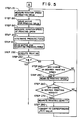
- step 160 It is then monitored if the print start key provided on the operation panel 1100 is keyed in or not; that is, it is monitored whether printing is to be started or not (step 160). If printing is to be started, the printing drum starts to be driven to the set rotation speed. Whether rotation of the printing drum is accelerated to the set rotation speed from stopped state or from rotated state during printing, an abrupt change in speed is unfavorable, and a moderate change in printing speed is preferred. On the other hand, since printing density depends on rotation speed of the printing drum, printing density should be adjusted by pressing force if the printing speed is changed.
- the present embodiment employs, as described below with reference to FIG. 5, a method in which a compensation amount of pressing force is properly determined in response to variation in monitored rotation speed of the printing drum. However, the method for compensation may be such that determines a rotation speed of the printing drum in response to variation in the pressing force being monitored.
- the CPU 1201 collects information on rotation speed of the printing drum from a rotation speed sensor such as a rotary encoder fitted to the printing drum or a motor for driving the printing drum (step 170). Let the observed rotation speed of the printing drum be f t1 and a desired rotation speed of the printing drum stored in the RAM 1203 be f e .
- the CPU 1201 compares f t1 with f e , and if the difference between them is 30 rpm or more, a control signal is output to the motor drive circuit 1311 for accelerating or decelerating the printing drum by 30 rpm. When the difference is less than 30 rpm, a control signal is output to the motor drive circuit 1311 for driving the printing drum to match f t1 with f e (step 180).
- the CPU 1201 outputs an operation signal to the motor drive circuit 1301 for controlling the pressing force in such a manner that the calculated proper pressing force should be realized.
- the motor 1302 for adjustment of pressing force is driven in accordance with the thus output signal, and the nut member 99 is rotated so that the pressing force is set at a proper value while the tensioning of the tensile coil spring 101 is optimized (step 210).
- the counter value N is incremented every time printing is executed on a sheet of printing paper, and the counter value is rewritten (step 220).
- the number of copies P is compared with the counter value N, and printing is stopped when N is a value not smaller than P (step 2 30). If N is smaller than P, it is confirmed whether the desired printing speed is changed or not during the printing operation (step 240). If the desired rotation speed of the printing drum is changed to f g , the rotation speed of the printing drum stored in RAM 1203 is rewritten from f e to f g (step 250). Then, it is confirmed whether the desired printing density is changed or not during the printing operation (step 260).
- the desired density index is changed to n h , it is converted into a corresponding value H of ⁇ (F/f) (step 270), and the value E of ⁇ (F/f) stored in RAM 1203 is rewritten to H (step 280).
- H the value of ⁇ (F/f)
- step 280 the value of ⁇ (F/f) stored in RAM 1203 is rewritten to H.
- Printing was performed using a rotary stencil printing device shown in FIG. 1 controlled by the method for controlling the printing density according to the present invention and under various printing conditions differing in the value of ⁇ (F/f).
- Commercially available stencil sheets (Model GR76W, manufactured by Riso Kagaku Corporation) were processed to obtain masters for stencil printing under the same conditions, and sheets of wood-free paper (Riso A3-size printing paper manufactured by Riso Kagaku Corporation) were printed by use of a commercially available stencil printing ink (GR ink, black, manufactured by Riso Kagaku Corporation) as a printing ink.
- Rotation speed of the printing drum was measured in unit of rpm by using a rotary encoder.
- the pressing force of the press roller was measured in unit of kg ⁇ f by a load cell which was pressed by the entire press roller while the press roller is under pressing operation by the drive unit.
- Printing density of printed image was evaluated by using a reflection densitometer (Model RD 920 manufactured by Macbeth Corp.), as well as by visual observation. The results of evaluation are shown in Tables 1 and 2.
- the value of ⁇ (F/f) or ⁇ (F/(f•W)) is found to be an index useful for controlling printing density without necessity of laborious experiments on a vast number of combinations of rotation speed of the printing drum with pressing force applied to printing paper against the printing drum. According to the present invention, a combination of the rotation speed with the pressing force to yield a constant printing density can readily be determined. Thus, the present invention enables a wide and fine adjustment of printing density while making the best use of performance of a stencil printing device.
Landscapes
- Inking, Control Or Cleaning Of Printing Machines (AREA)
Abstract
Description
- The present invention relates to a method for controlling printing density in stencil printing, which is capable of easily controlling the printing density, and to a device for the same.
- Well known in the art is a stencil printing device in which a perforated stencil sheet is wound around a circumferential surface of a printing drum with an ink supplied thereto, and in which the ink is transferred from the printing drum to a printing sheet through the perforated stencil sheet by pressing the printing sheet to the printing drum while the drum is rotated.
- In a stencil printing above, it has been proposed in Japanese patent publication (Kokai) No. 62-127276 that printing density of an image to be printed on a printing sheet is variably set by variably setting a pressing force to be applied to the printing sheet against the printing drum, in accordance with printing density information given by a means for setting printing density information, for instance, a printing density set up key provided on an operation panel.
- Furthermore, since the printing density in stencil printing changes with printing speed, Japanese patent publication (Kokai) No. 06-155880 has already proposed a method for implementing stencil printing at a desired density irrespective of the change in printing speed. This method comprises variably setting a pressing force applied to the printing sheet against the printing drum, in accordance with printing speed information given by a means for setting printing speed information, for instance, a printing speed set up key provided on an operation panel.
- With recent diversification in quality of printing paper and originals, there is a demand on a stencil printing device which can more widely and finely control printing density. However, because no index for controlling printing density has been clarified, such a demand could only be satisfied by collecting voluminous data on combinations of a rotation speed of a printing drum and a corresponding pressing force applied to a printing sheet with respect to various printing densities. Thus, it was practically unfeasible to load the entire data into a stencil printing device to control printing density.
- In view of such problems as above, an object of the present invention is to provide a method and an apparatus for controlling printing density in stencil printing, which are capable of widely and finely varying the printing density at a desired printing speed.
- As a result of the present inventor's intensive studies under the above object, it has been found that the quantity of printed ink depends on a value of √(F/f) (where F is a pressing force at which a printing sheet is pressed to a printing drum, and fis a rotation speed of the drum), and more particularly, that the quantity is approximately proportional to the value of √(F/f). This means that, even if rotation speed of the drum is varied, the same printing density can be obtained by performing stencil printing at a pressing force which yields the same value of √(F/f).
- Conventionally, the degree of pressing force that compensates for a change of printing speed to obtain the same printing density has to be determined only by experience. However, according to the method of the present invention, a printing speed and a pressing force can be readily set by selecting a value of √(F/f) as an index of printing density. Therefore, whether printing is put to trial at a low printing speed or into practice at a high printing speed, or even when printing speed is changed during printing, a printer can be controlled so that copies with a constant printing density are provided independently of printing speed.
- In accordance with one aspect of the present invention, there is provided, in a stencil printing in which a perforated stencil sheet is wound around an outer circumferential surface of a printing drum to the inner surface of which an ink is supplied, and the ink is transferred from the printing drum to a printing sheet through the perforated stencil sheet by pressing the printing sheet to the printing drum while the drum is rotated, a method for controlling a printing density which comprises controlling an amount of an ink transferred to a printing sheet by selecting a specific value of D from a range predetermined in accordance with the following equation:
- The present method for controlling a printing density in stencil printing may comprise a first step of selecting a specific value of D from said predetermined range in order to set a desired printing density, a second step of calculating a possible range of f at the selected value of D and selecting a specific value of f from the calculated range in order to set a desired printing speed, and a third step of calculating a pressing force of F at the selected values of D and f in order to set a pressing force. Furthermore, said second step may comprise a step of calculating a possible range of f at the selected value of D and indicating the calculated range off, and a step of selecting a specific value of f from the indicated range in order to set a desired printing speed.
- The present method for controlling a printing density in stencil printing may comprise a first step of selecting a specific value of fin order to set a desired printing speed, a second step of calculating a possible range of D at the selected value of f and selecting a specific value of D from the calculated range in order to set a desired printing density, and a third step of calculating a pressing force of F at the selected values of D and f in order to set a pressing force. Furthermore, said second step may comprise a step of calculating a possible range of D at the selected value of f and indicating the calculated range of D, and a step of selecting a specific value of D from the indicated range in order to set a desired printing density.
- In accordance with another aspect of the present invention, there is provided, in a stencil printing in which a perforated stencil sheet is wound around an outer circumferential surface of a printing drum to the inner surface of which an ink is supplied, and the ink is transferred from the printing drum to a printing sheet through the perforated stencil sheet by pressing the printing sheet to the printing drum while the drum is rotated, a method for controlling a printing density, which comprises providing a value of D in accordance with the following equation:
- In accordance with still another aspect of the present invention, there is provided a device for controlling a printing density for use in stencil printing in which a perforated stencil sheet is wound around an outer circumferential surface of a printing drum to the inner surface of which an ink is supplied, and the ink is transferred from the printing drum to a printing sheet through the perforated stencil sheet by pressing the printing sheet to the printing drum while the drum is rotated, which comprises a means for setting a specific value of D within a range predetermined in accordance with the following equation:
- The printing density controlling device according to the present invention may comprise a printing density setting means for setting a specific value of D within said predetermined range, a printing speed setting means for calculating a possible range of f at the above-set value of D and setting a specific value of f within the calculated range, and a pressing force regulating means for calculating a value of F at the above-set values of D and f and setting the pressing force to the calculated value of F. Furthermore, in this device, the printing speed setting means may comprise an indication means which calculates a possible range of f at the above-set value of D and indicates the range off, and a speed selecting means which allows a specific value of f to be selected from the indicated range to set a desired printing speed.
- The printing density controlling device according to the present invention may comprise a printing speed setting means for setting a specific value of f to set a desired printing speed, a printing density setting means for calculating a possible range of D at the above-set value of f and setting a specific value of D within the calculated range to set a desired printing density, and a pressing force regulating means for calculating a value of F at the above-set values of D and f and setting the pressing force to the calculated value of F. Furthermore, in this device, the printing density setting means may comprise an indication means which calculates a possible range of D at the above-set value of f and indicates the range of D, and a printing density selecting means which allows a specific value of D to be selected from the indicated range to set a desired printing density.
- In accordance with still another aspect of the present invention, there is provided a computer program storage medium containing a program for controlling a printing density, for use in a stencil printing in which a perforated stencil sheet is wound around an outer circumferential surface of a printing drum to which an ink is supplied, and the ink is transferred from the printing drum to a printing sheet through the perforated stencil sheet by pressing the printing sheet to the printing drum while the drum is rotated, said program comprising the following equation:
- The program may comprise the steps of storing a selected value of D, calculating a possible range of f at the stored value of D, storing a value of f selected from the range of f, and calculating a value of F at the stored values of D and f for setting a pressing force.
- In the computer program storage medium above, the program may comprise the steps of storing a selected value of D, calculating a possible range of f at the stored value of D and indicating the range of f for selection, storing a value of f selected from the indicated range of f, and calculating a value of F at the stored values of D and f for setting a pressing force.
- Alternatively, in the computer program storage medium above, the program may comprise the steps of storing a selected value of f, calculating a possible range of D at the stored value off, storing a value of D selected from the range of D, and calculating a value of F at the stored values of f and D for setting a pressing force.
- The program may comprise the steps of storing a selected value of f, calculating a possible range of D at the stored value of f and indicating the range of D for selection, storing a value of D selected from the indicated range of D, and calculating a value of F at the stored values of f and D for setting a pressing force.
- In the present invention, the equation D = √(F/f) is equivalent to D2 = (F/f), and selecting a value of D means selecting a value of D2. Furthermore, it is also possible to derive equations expressed by, for example, D' = a√(F/f) + b (where a and b are each an arbitrary constant). Needless to say, in the thus derived equations, selecting a value of D' means selecting a value of D.
- In addition, the rotation speed f (rpm) of the printing drum is, in general, equivalent to a frequency per minute of repeated pressing of an arbitrarily fixed point of the printable outer circumferential surface of the printing drum. Thus, in an ordinary printer in which a piece of printing paper is fed per rotation of the drum, the rotation speed f(rpm) is equivalent to the number of copies finished in one minute. However, in case plural pieces of printing paper are fed per rotation of the drum, or in case only one piece of printing paper is fed while the drum rotates more than one time, the rotation speed of the drum does not necessarily agree with the printing speed, namely the number of copies finished in one minute. Furthermore, in case rotation of the drum is not constant (for instance, where the drum accelerates, decelerates or stops during one rotation), rotation speed f (rpm) of the drum meant by the present invention is derived from a surface speed of the drum at a fixed point, which can be converted into a rotation speed f (rpm).
- Hereinafter, the present invention will be described in more detail with reference to the appended drawings, in which:
- FIG. 1 is a side cross sectional view which schematically shows the inner structure of an embodiment of a stencil printing device according to the present invention;
- FIG. 2 is a side view of a drive unit used for the press roller shown in FIG. 1;
- FIG. 3 is a block diagram showing an embodiment of the control unit of a stencil printing device according to the present invention;
- FIG. 4 is a flow chart showing a control operation of the control unit of FIG. 3 before starting printing; and
- FIG. 5 is a flow chart showing a control operation of the control unit of FIG. 3. during printing.
-
- FIG. 1 shows a preferred embodiment of the stencil printing device according to the present invention, which is equipped with a plate making function. This stencil printing device comprises an original reading unit 11, a
plate making unit 13, and aprinting unit 15. - The original reading unit 11 essentially consists of an image scanner, and comprises a
line image sensor 17 for reading an original image of an original sheet conveyed in a secondary scanning direction, and an originalsheet feeding roller 19. - The
plate making unit 13 comprises a stencilsheet roll unit 21, a thermal printing head 2 3 consisting of a plurality of dot-like heat generating elements arranged in a lateral row, master platesheet feeding rollers 25 and 2 7, master platesheet guide rollers thermal printing head 23 are selectively activated so that a desired thermal perforation may be carried out on the master plate sheet M, which is heat sensitive, as a plate making process, and the master plate sheet cutter 35 cuts the stencil master plate sheet M after the latter is processed into a master plate. - The
printing unit 15 comprises acylindrical printing drum 37 made of a perforated metal plate, a mesh structure or an otherwise ink permeable porous structure, anink supplying unit 39 essentially consisting of asqueegee roller 38 and adoctor roller 40 disposed inside theprinting drum 37, and apress roller 41, and the stencil master plate sheet M after being processed into a master plate is mounted on the outer circumferential surface of theprinting drum 37. - On one side of the
printing unit 15 is provided apaper feeding unit 43, and on the other side of theprinting unit 15 is provided apaper ejecting unit 45. - The
paper feeding unit 43 comprises a paper feeding table 47 on which a stack of printing paper P is placed, pick uprollers 49 for picking up the printing paper P on the paper feeding table 47 sheet by sheet, andtiming rollers 51 for delivering the printing paper P to the nip between the printing drum 3 7 and thepress roller 41. - The
paper ejecting unit 45 comprises apeeling claw 53 for removing the printing paper from theprinting drum 37, an ejectedpaper feeding belt 55, and an ejected paper table 57 for stacking up the printed printing paper. - On one side of the
printing unit 15 is provided a masterplate ejecting unit 63 comprising masterplate ejecting rollers 61 for peeling off the used stencil master plate sheet M from theprinting drum 37 and delivering it into an ejectedmaster plate box 59. - In this stencil printing device, printing ink of a desired color is supplied by the
ink supplying unit 39 into the inner surface of theprinting drum 37 while theprinting drum 37 is rotated counter clockwise in the drawing around its central axial line by rotative drive means not shown in the drawings. Printing paper P is delivered to the nip between thepress roller 41 and theprinting drum 37 after being fed by the paperfeed timing rollers 51 from the left to right in synchronism with the rotation of theprinting drum 37 at an appropriate timing. The printing paper P is thus pressed upon theprinting drum 37 by thepress roller 41 onto the stencil master plate sheet M mounted on the outer circumferential surface of the printing drum, and a stencil printing is carried out on the printing paper P by using the printing ink of the desired color. - FIG. 2 shows the drive unit for the
press roller 41. Thepress roller 41 is supported by abracket 65, extending in the axial direction of theprinting drum 37, so as to be rotatable around its central axial line, and thebracket 65 is in turn fixedly secured to apress shaft 69 rotatably supported by a fixed member or frame not show in the drawings. Thus, thepress roller 41 is vertically rotatable around thepress shaft 69, and can move between a retracted position spaced from the outer circumferential surface of theprinting drum 37 and a position for pressing action engaged upon the outer circumferential surface of theprinting drum 37. Thepress shaft 69 carries apress drive lever 71 fixedly mounted thereof, and rotatably supports a press drive plate 73. - A
hook member 77 is pivotally supported on the press drive plate 73 by means of apivot shaft 75, and selectively engages with thepress drive lever 71 by being rotatively driven by asolenoid 79 mounted on the press drive plate 73 for selectively engaging thepress drive lever 71 with the press drive plate 73. - An end of a
first link member 83 is pivotally connected to an end of the press drive plate 73 by means of apivot shaft 81. Thefirst link member 83 is provided with a pair ofslots 85 extending in the same direction, and theseslots 85 receivepins 89 of asecond link member 87. Thus, thefirst link member 83 and thesecond link member 87 are connected with each other so as to be relatively moveable in the lengthwise direction or vertically as seen in FIG. 2 within the range permitted by theslots 85. - The lower end of the
first link member 83 is provided with abent flange piece 91 through which an adjustscrew 93 is passed so as to be adjustable in the direction of the reciprocating movement of thefirst link member 83. The adjustscrew 93 threads with anut member 99 provided withouter teeth 97 in the manner of a spur gear and supported by the lower surface of thebent flange piece 91 by way of acollar 95 against a thrust force, and the upper end of the adjustscrew 93 is connected to an end of atensile coil spring 101. - The adjust
screw 93 is thus prevented from rotating by being engaged by the one end of thetensile coil spring 101, and is axially displaced with respect to thefirst link member 83 by the rotation of thenut member 99. Thetensile coil spring 101 is engaged by one of thepins 89 at its other end, thus urging thefirst link member 83 upwards relative to the second link member 8 7, or in other words urging the press drive plate 73 in counter clockwise direction in FIG.2 around thepress shaft 69 to press thepress roller 41 onto the outer circumferential surface of theprinting drum 37. - The
second link member 87 is pivotally connected to a free end portion of acam lever 105 by apivot shaft 103. Thecam lever 105 is rotatably supported on a frame not shown in the drawings by asupport shaft 107. Thecam lever 105 rotatably supports acam follower roller 109 in a freely rotatable manner. Thecam follower roller 109 engages with apress cam 113 mounted on a main shaft 111. The main shaft 111 is rotatably supported by a frame not shown in the drawings. - The
press cam 113 rotates in synchronism with the printing drum 3 7, and is provided with a cam profile which moves thepress roller 41 to its retracted position to avoid the interference between thepress roller 41 and a clamp unit when the clamp unit is located in a position corresponding to thepress roller 41. The clamp unit is not shown in the drawings, but disposed on an outer circumferential surface of theprinting drum 37 to clamp an end of a stencil master plate sheet wound around the drum as in conventional stencil printing machines. - The
bent flange piece 91 carries anelectric motor 1302 for adjusting the pressing force, and adrive gear 119 is fixedly secured to anoutput shaft 117 of the electric motor. Thedrive gear 119 meshes with theouter teeth 97 of thenut member 99 for transmitting the rotation of theoutput shaft 117 of theelectric motor 1302 for adjusting the pressing force. - In this press roller drive unit, the rotation of the
printing drum 37 causes thepress cam 113 to rotate in the clockwise direction as seen in FIG. 2, and this rotation in turn causes a substantially vertical reciprocating movement of thesecond link member 87 which is transmitted to thefirst link member 83 via thetensile coil spring 101. The reciprocating movement of thefirst link member 83 causes the press drive plate 73 to angularly reciprocate around thepress shaft 69, and because thehook member 77 is moved into engagement with thepress drive lever 71 by thesolenoid 79, the reciprocating movement of the press drive plate 73 is transmitted to thepress shaft 69. Thus, the reciprocating angular movement of thepress shaft 69 causes thepress roller 41 to vertically rotate around thepress shaft 69 so that thepress roller 41 may move between the retracted position spaced from the outer circumferential surface of theprinting drum 37 and the pressing position where theroller 41 is pressed against the outer circumferential surface of theprinting drum 37. - The movement of the
press roller 41 to the pressing position is effected by thesecond link member 87 being lifted, by this movement being transmitted to thefirst link member 83 through tensioning of thetensile coil spring 101, and by the press drive plate 73 being rotated in counter clockwise direction as seen in FIG. 2 around thepress shaft 69 of the press drive plate 73. Thus, thepress roller 41 is pressed against the outer circumferential surface of theprinting drum 37 with the printing paper P interposed therebetween, thereby restricting any further rotation of the press drive plate 73 in counter clockwise direction as seen in FIG. 2 around thepress shaft 69. Thesecond link member 87 is further lifted until thesecond link member 87 moves relative to thefirst link member 83 and thetensile coil spring 101 is extended. As a result, the spring force of the stretchedtensile coil spring 101 presses thepress roller 41 on the outer circumferential surface of theprinting drum 37 with printing paper P interposed therebetween, and the magnitude of the pressing force is determined by this spring force. - For adjusting the pressing force, the
electric motor 1302 for the adjustment of the pressing force is activated, and thedrive gear 119 is rotated. The rotation of thedriver gear 119 is transmitted to thenut member 99, and the rotation of thenut member 99 causes the adjustscrew 93 to move axially relative to the first link member 8 3, thereby changing the position of the adjustscrew 93 relative to thefirst link member 83. As a result, the point of engagement between thetensile coil spring 101 and the adjustscrew 93 moves axially relative to thefirst link member 83, and this displacement causes a change in the length of thetensile coil spring 101, and hence its preset spring force. The change in the preset force of thetensile coil spring 101 changes the pressure, that is, the pressing force by which thepress roller 41 is pressed against the outer circumferential surface of theprinting drum 37 as described above. It can be clearly understood that such a means as a solenoid, an air cylinder and a hydraulic pressure is also usable as a means for generating the pressing force. - As described in Japanese patent publication (kokoku) No. 62-28757, the
printing drum 37 for use in the present embodiment is supported on a movable support frame as a unit together with an ink bottle accommodating printing ink therein, an ink delivery pump for drawing printing ink from the ink bottle and delivering it to the supplyingunit 39, and a drive motor for the ink delivery pump. The entire unit can be replaceably loaded into the body of the stencil printing device. For more details of the replaceable structure of the printing drum unit, reference should be made to Japanese patent publication (kokoku) No. 62-28757. - FIG. 3 shows the control unit which totally controls the operation of the stencil printing device inclusive of the operation control of the
electric motor 1302 for the adjustment of the pressing force, in which only the parts of the stencil printing device which are related to the present invention are illustrated for the simplification of description. - The control unit of FIG. 3 comprises a
CPU 1201 consisting of a micro processor or something like that, aROM 1202 storing programs for controlling the operation of various units in the stencil printing device, and aRAM 1203 storing, as required, results of arithmetic operations carried out by the micro processor and various input information. - The stencil printing device comprises an
operation panel 1100 equipped with a ten key pad 1101 for setting the desired number of copies, a printing speed set up key 1102, a printing density set up key 1103, a printing start key 1104, and adisplay panel 1105, and theCPU 1201 receives, for instance, information on the desired number of copies set up on the ten key pad 1101; information on printing speed set up by the printing speed set up key 1102, that is, information on rotation speed of the printing drum; information on a relative printing density set by the printing density set up key 1103, that is, information on a value of √(F/f); and information commanding a start of printing set by theprinting start key 1104. Based on the input information on the printing speed, theCPU 1201 controls thedrive motor 1312 for the printing drum via themotor drive circuit 1311 for driving the printing drum, and receives information on an actual rotation speed of the printing drum fed back from arotation speed sensor 1313 for the printing drum. - The
CPU 1201 determines a pressing force in performing printing based on the set value of √(F/f) and the rotation speed of the printing drum, either by calculation or with reference to a table in which previously-calculated results are stored. TheCPU 1201 also determines an operation quantity of themotor 1302 for adjustment to a targeted pressing force, and outputs the operation quantity to themotor drive circuit 1301. Furthermore, when rotation speed of the printing drum is accelerated or decelerated during printing, themotor 1302 for the adjustment of the pressing force is controlled to increase or decrease the pressing force to maintain the previously set value of √(F/f) to be substantially constant. - A control flow for adjustment operation of printing density for the stencil printing device according to the present invention is shown in FIG. 4 and FIG. 5. In the control flow, a printing mode is first selected to give priority to either density or speed (step 100).
- When a mode giving priority to density is selected, a desired printing density is set by the printing density set up key 1103 on the
operation panel 1100. The printing density maybe set by direct input of a value of √(F/f) by the ten key pad or the like, or may be selected by keys or a volume dial from several "dense" to "pale" levels so that the user can easily set the value. - As an example of the case not using the direct input of the value of √(F/f), a method of indirectly setting the value of √(F/f) by entering or selecting a numeral from a range of 1 to 20 using keys or a volume dial is described below. In a printer capable of variably controlling the pressing force in a range of from 10 to 20 kgf and the rotation speed of the printing drum in a range of from 30 to 120 rpm, the value of √(F/f) is variable and controllable in a range of from 0.289 to 0.816. More specifically, the printing density is variable and controllable in a range the minimum printing density of which is a printing density obtained in a printing condition that yields 0.289 as a value of √(F/f), and the maximum printing density of which is a printing density obtained in a printing condition that yields 0.816 as a value of √(F/f).
- In the printer above, the printing density may be represented by a density index n which is a value or integer between 1 and 20 corresponding to a value of √(F/f) according to the following equation (1):
- In this way, a condition for the least dense printing can be set by entering numeral 1 as a density index on the
operation panel 1100, which is then calculated into 0.289 as the value of √(F/f). When a denser printing is preferred, a larger numeral n is input. If the maximum printing density is needed, a value of 20 as a density index is entered. - In this specific example, the possible range for setting the printing density corresponds to the entire range of controllable value of √(F/f), but may be limited to a range most frequently used. Furthermore, the increment of √(F/f) per density index is constant in equation (1), but may be partially narrowed or broadened.
- In case the range of the frequently used value of √(F/f) changes depending on variation in such factors as frequency in use, type of inks, and environmental temperature and other environmental conditions of printers, a sensor may be installed in the printer to detect a change in these factors in order that the above equation is modified or supplemented with a coefficient or a constant so as to facilitate selection of the printing density.
- Then, a density index is input by operating the printing density set up key 1103 on the
operation panel 1100. Let the density index input here be nc (step 110). TheCPU 1201 converts the density index nc into a value of √(F/f) by calculation according to the following equation (2) or with reference to a table in which previously calculated results are stored, and stores the value inRAM 1203. Let the value of √(F/f) calculated in accordance with the equation (2) be C (step 120): - From the
ROM 1202, theCPU 1201 reads out the maximum and minimum values Fmax and Fmin of the pressing force controllable by the printer, as well as the maximum and minimum values fmax and fmin of the rotation speed of the printing drum controllable by the printer. Then, values of fa and fb are determined by calculation in accordance with the equation (3) below, or with reference to a table in which previously calculated results are stored.
- As a result of calculation, if fa is not greater than fmin, fmin is set as the minimum value of the controllable rotation speed of the printing drum, and if fmin is not greater than fa, fa is set as the minimum value. Similarly, if fmax is not greater than fb, fmax is set as the maximum value, and if fb is not larger than fmax, fb is set as the maximum value of the controllable rotation speed of the printing drum. Then, the maximum value and the minimum value thus determined are displayed on the operation panel 1100 (step 130).
- Then, the user inputs information on the rotation speed of the printing drum by selecting a value from the range of the rotation speed displayed on the panel using the printing speed set up key 1102, and the input value is then stored in the
RAM 1203. Let the rotation speed of the printing drum set in this step be fc (step 140). - When a mode giving priority to printing speed is selected, a desired rotation speed of the printing drum is set by the printing speed set up key 1102 provided on the
operation panel 1100, so that information on the rotation speed of the printing drum is stored in theRAM 1203. Let the rotation speed of the printing drum set herein be fd (step 300). - The
CPU 1201 reads out, from theROM 1202, the maximum and minimum values Fmax and Fmin of the pressing force controllable by the printer, and also reads out the rotation speed of the printing drum fd from theRAM 1203. Then, the maximum value Dmax and the minimum value nmin of the selectable density index are determined by calculation in accordance with the equation (4) below, or with reference to a table in which previously calculated results are stored.
- The
operation panel 1100 displays a range of selectable printing density indices, in which nmin is the least dense printing density, and nmax is the most dense printing density (step 310). - A desired printing density is input by selecting a density index from the range of the density indices displayed on the
operation panel 1100 using the printing density set up key 1103. Let the density index set here be nd (step 320). - The
CPU 1201 determines the value of √(F/f) by calculation according to the equation (5) below or with reference to a table in which previously calculated results are stored, and stores the value inRAM 1203. Let the value of √(F/f) calculated in accordance with equation (5) be D (step 330): - The number of copies is set by entering the ten key pad 1101 on the
operation panel 1100, and the copy number information is stored in the RAM 1203 (step 150). - It is then monitored if the print start key provided on the
operation panel 1100 is keyed in or not; that is, it is monitored whether printing is to be started or not (step 160). If printing is to be started, the printing drum starts to be driven to the set rotation speed. Whether rotation of the printing drum is accelerated to the set rotation speed from stopped state or from rotated state during printing, an abrupt change in speed is unfavorable, and a moderate change in printing speed is preferred. On the other hand, since printing density depends on rotation speed of the printing drum, printing density should be adjusted by pressing force if the printing speed is changed. The present embodiment employs, as described below with reference to FIG. 5, a method in which a compensation amount of pressing force is properly determined in response to variation in monitored rotation speed of the printing drum. However, the method for compensation may be such that determines a rotation speed of the printing drum in response to variation in the pressing force being monitored. - Referring to FIG. 5, first of all, the
CPU 1201 collects information on rotation speed of the printing drum from a rotation speed sensor such as a rotary encoder fitted to the printing drum or a motor for driving the printing drum (step 170). Let the observed rotation speed of the printing drum be ft1 and a desired rotation speed of the printing drum stored in theRAM 1203 be fe. TheCPU 1201 compares ft1 with fe, and if the difference between them is 30 rpm or more, a control signal is output to themotor drive circuit 1311 for accelerating or decelerating the printing drum by 30 rpm. When the difference is less than 30 rpm, a control signal is output to themotor drive circuit 1311 for driving the printing drum to match ft1 with fe (step 180). - After the speed has been changed in accordance with the control signal, the
CPU 1201 reads rotation speed information of the printing drum again (step 190). Let the observed rotation speed of the printing drum be ft2 and the value of the density information √(F/f) set in theRAM 1203 be E. Then, theCPU 1201 determines a proper pressing force by calculation according to the equation (6) below or with reference to a table in which previously calculated results are stored (step 200). - Then, the
CPU 1201 outputs an operation signal to themotor drive circuit 1301 for controlling the pressing force in such a manner that the calculated proper pressing force should be realized. Themotor 1302 for adjustment of pressing force is driven in accordance with the thus output signal, and thenut member 99 is rotated so that the pressing force is set at a proper value while the tensioning of thetensile coil spring 101 is optimized (step 210). - The counter value N is incremented every time printing is executed on a sheet of printing paper, and the counter value is rewritten (step 220). The number of copies P is compared with the counter value N, and printing is stopped when N is a value not smaller than P (step 2 30). If N is smaller than P, it is confirmed whether the desired printing speed is changed or not during the printing operation (step 240). If the desired rotation speed of the printing drum is changed to fg, the rotation speed of the printing drum stored in
RAM 1203 is rewritten from fe to fg (step 250). Then, it is confirmed whether the desired printing density is changed or not during the printing operation (step 260). If the desired density index is changed to nh, it is converted into a corresponding value H of √(F/f) (step 270), and the value E of √(F/f) stored inRAM 1203 is rewritten to H (step 280). The information on changes in the rotation speed of the printing drum and the printing density is reflected tosteps - Printing was performed using a rotary stencil printing device shown in FIG. 1 controlled by the method for controlling the printing density according to the present invention and under various printing conditions differing in the value of √(F/f). A gray chart having an image area ratio of 11%, which is sensitive to slight change in printing density, was used as an original. Commercially available stencil sheets (Model GR76W, manufactured by Riso Kagaku Corporation) were processed to obtain masters for stencil printing under the same conditions, and sheets of wood-free paper (Riso A3-size printing paper manufactured by Riso Kagaku Corporation) were printed by use of a commercially available stencil printing ink (GR ink, black, manufactured by Riso Kagaku Corporation) as a printing ink.
- Rotation speed of the printing drum was measured in unit of rpm by using a rotary encoder. The pressing force of the press roller was measured in unit of kg· f by a load cell which was pressed by the entire press roller while the press roller is under pressing operation by the drive unit. Printing density of printed image was evaluated by using a reflection densitometer (Model RD 920 manufactured by Macbeth Corp.), as well as by visual observation. The results of evaluation are shown in Tables 1 and 2.

Rotation speed of printing drum (rpm) 30 30 30 45 60 80 80 120 100 120 Pressing force (kg· f) 20 18 15 20 16 18 13 15 12 11 Value of √(F/f) 0.82 0.77 0.71 0.67 0.52 0.47 0.40 0.35 0.35 0.30 Reflection density 0.27 0.26 0.25 0.24 0.20 0.19 0.17 0.16 0.16 0.15 Difference in value of √(F/f) 0.05 0.04 0.05 0.05 0.05 Visual observation on printing density - - - - - Note:
+ means that a difference in density was observed.
- means that no difference in density was observed. - From Tables 1 and 2, it can be seen that the value of √(F/f) is substantially proportional to printing density, and that the printing density can be controlled as desired by using the value of √(F/f). It has also been found that even when the rotation speed of the printing drum is varied, a stable printing density can be realized by selecting a pressing force so as to maintain the value of √(F/f) constant. Furthermore, it has been found that so long as variation in the value of √(F/f) falls within ±0.05, no difference in printing density is visually distinguishable.
- Data on Tables 1 and 2 were obtained using a press roller of 0.31m in length. Further, printing was performed in the same manner as above, except that a press roller of different length was used. The results are shown in Table 3.
Length of press roller W (m) 0.31 0.31 0.31 0.31 0.21 0.21 0.21 0.062 0.062 0.062 Pressing force F(kg· f) 20 40 80 100 14 50 70 10 16 20 Rotation speed of printing drum f(rpm) 30 60 120 150 30 110 150 15 24 30 F/W 64.5 129.0 258.1 322.6 66.7 238.1 333.3 161.3 258.1 322.6 Value of √(F/f) 0.82 0.82 0.82 0.82 0.68 0.67 0.68 0.82 0.82 0.82 Value of √(F/(f·W)) 1.47 1.47 1.47 1.47 1.49 1.47 1.49 3.28 3.28 3.28 Reflection density D 0.27 0.28 0.28 0.27 0.28 0.28 0.27 0.50 0.51 0.51 Visual observation on printing density - - - Note:
+ means that a difference in density was observed.
- means that no difference in density was observed. - From Table 3, it has been confirmed that the value of √(F/f) is useful for controlling printing density on press rollers of different length . Also, it has been confirmed from Tables 1 to 3 that printing density is proportional to the value of √(F/f•W)) as it is shown by an equation of D = 0.128√(F/(f•W)) + 0.087, regardless of length of press rollers.
- As can be understood from the above description, according to the present invention, the value of √(F/f) or √(F/(f•W)) is found to be an index useful for controlling printing density without necessity of laborious experiments on a vast number of combinations of rotation speed of the printing drum with pressing force applied to printing paper against the printing drum. According to the present invention, a combination of the rotation speed with the pressing force to yield a constant printing density can readily be determined. Thus, the present invention enables a wide and fine adjustment of printing density while making the best use of performance of a stencil printing device.
- Although the present invention has been described in terms of a specific embodiment thereof, it is possible to modify and alter details thereof without departing from the spirit and scopes of the present invention.
Claims (12)
- A method for controlling a printing density in a stencil printing system in which a perforated stencil sheet is wound around a circumferential surface of a printing drum to which ink is supplied, and the ink is transferred from the printing drum to a printing sheet through the perforated stencil sheet by pressing the printing sheet to the printing drum while the drum is rotated,
the method for controlling a printing density comprising
controlling an amount of an ink transferred to a printing sheet in accordance with the following equation: - A method according to claim 1, which comprisesselecting a specific value of D from a predetermined range in order to set a desired printing density,calculating a possible range of f at the selected value of D and selecting a specific value of f from the calculated range in order to set a desired printing speed, andcalculating a pressing force of F at the selected values of D and f in order to set a pressing force, preferably comprising indicating the calculated range of f, and selecting the specific value of f from the indicated range.
- A method according to claim 1, which comprisesselecting a specific value of f in order to set a desired printing speed,calculating a possible range of D at the selected value of f and selecting a specific value of D from the calculated range in order to set a desired printing density, andcalculating a pressing force of F at the selected values of D and fin order to set a pressing force, preferably comprising indicating the calculated range of D, and selecting the specific value of D from the indicated range.
- A method as defined in any one of claims 1 to 3, further comprising regulating the value of F or f in such a manner that a variation of the value of D is kept within ±0.05 (kg.f/rpm) so that printing density is maintained substantially constant.
- A method as claimed in claim 4 including monitoring the value of F and regulating the value of f to keep the variation of D within ±0.05 (kg.f/rpm).
- A method as claimed in claim 4 including monitoring the value of f and regulating the value of F to keep the variation of the value D within ±0.05 (kg· .f/rpm).
- A method for controlling printing density in a stencil printing system in which a perforated stencil sheet is wound around a circumferential surface of a printing drum to which ink is supplied, and the ink is transferred from the printing drum to a printing sheet through the perforated stencil sheet by pressing the printing sheet to the printing drum while the drum is rotated,
the method comprising
providing a value of D in accordance with the following equation:
regulating the value of F or f in such a manner that a variation of the value of D is kept within ±0.05 (kg·f/rpm) so that printing density is substantially maintained constant. - A method according to claim 7, comprising monitoring the value of F, and regulating the value of f to keep the variation of the value of D within ±0.05 (kg.f/rpm).
- A printing method as defined in claim 7 further comprising monitoring the value of f, and regulating the value of F to keep the variation of the value of D within ±0.05 (kg.f/rpm).
- A device for controlling a printing density for use in a stencil printing system in which a perforated stencil sheet is wound around a circumferential surface of a printing drum to which an ink is supplied, and the ink is transferred from the printing drum to a printing sheet through the perforated stencil sheet by pressing the printing sheet to the printing drum which the drum is rotated,
wherein the device comprises a means for setting a specific value of D in accordance with the following equation: - A device as defined in claim 10, which comprisesa printing speed setting means for calculating a possible range of fat the set value of D and setting a specific value of f within the calculated range, anda pressing force regulating means for calculating a value of F at the set values of D and f and setting the pressing force to the calculated value of F, preferably wherein said printing speed setting means comprises an indication means which calculates a possible range of f at the set value of D and indicates the range of f, and a speed selecting means which allows a specific value of f to be selected from the indicated range to set a desired printing speed.
- A device as defined in claim 10, which comprisesa printing speed setting means for setting specific value of f to set a desired printing speed,a printing density setting means for calculating a possible range of D at the set value of f and setting a specific value of D within the calculated range to set a desired printing density, anda pressing force regulating means for calculating a value of F at the set values of D and f and setting the pressing force to the calculated value of F, preferably in which said printing density setting means comprises an indication means which calculates a possible range of D at the set value of f and indicates the range of D, and a printing density selecting means which allows a specific value of D to be selected from the indicated range to set a desired printing density.
Applications Claiming Priority (3)
| Application Number | Priority Date | Filing Date | Title |
|---|---|---|---|
| JP28119597 | 1997-09-30 | ||
| JP281195/97U | 1997-09-30 | ||
| JP28119597U | 1997-09-30 |
Publications (2)
| Publication Number | Publication Date |
|---|---|
| EP0904949A1 true EP0904949A1 (en) | 1999-03-31 |
| EP0904949B1 EP0904949B1 (en) | 2001-11-28 |
Family
ID=17635678
Family Applications (1)
| Application Number | Title | Priority Date | Filing Date |
|---|---|---|---|
| EP98307964A Expired - Lifetime EP0904949B1 (en) | 1997-09-30 | 1998-09-30 | Method and device for controlling printing density in a stencil printing machine |
Country Status (3)
| Country | Link |
|---|---|
| US (1) | US6032578A (en) |
| EP (1) | EP0904949B1 (en) |
| CN (1) | CN1097513C (en) |
Cited By (1)
| Publication number | Priority date | Publication date | Assignee | Title |
|---|---|---|---|---|
| AT410182B (en) * | 2000-07-19 | 2003-02-25 | Peter Zimmer Keg | DEVICE FOR APPLYING COLOR ON A TRACK |
Families Citing this family (3)
| Publication number | Priority date | Publication date | Assignee | Title |
|---|---|---|---|---|
| JP3817116B2 (en) * | 2000-06-15 | 2006-08-30 | 理想科学工業株式会社 | Stencil printing machine |
| JP3658392B2 (en) * | 2002-12-27 | 2005-06-08 | キヤノン電子株式会社 | Signal output device and sheet material processing apparatus provided with signal output device |
| JP4464621B2 (en) * | 2003-04-07 | 2010-05-19 | 理想科学工業株式会社 | Stencil printing apparatus and printing method |
Citations (3)
| Publication number | Priority date | Publication date | Assignee | Title |
|---|---|---|---|---|
| JPH04344283A (en) * | 1991-05-20 | 1992-11-30 | Omron Corp | Printing device |
| JPH06155880A (en) * | 1993-06-29 | 1994-06-03 | Riso Kagaku Corp | Stencil printer |
| JPH06155882A (en) * | 1993-06-29 | 1994-06-03 | Riso Kagaku Corp | Stencil printer |
Family Cites Families (11)
| Publication number | Priority date | Publication date | Assignee | Title |
|---|---|---|---|---|
| JPS6155882A (en) * | 1984-08-27 | 1986-03-20 | シャープ株式会社 | Electromagnetic cooking device |
| JPS6155880A (en) * | 1984-08-28 | 1986-03-20 | 杉本練染株式会社 | Panel heater |
| JPS6228757A (en) * | 1985-07-30 | 1987-02-06 | Konishiroku Photo Ind Co Ltd | Photosensitive body |
| JPS62127276A (en) * | 1985-11-27 | 1987-06-09 | Riso Kagaku Corp | Stencil duplicator |
| JP3025361B2 (en) * | 1992-02-07 | 2000-03-27 | 理想科学工業株式会社 | Blade type squeegee device for stencil printing machine |
| JPH05286221A (en) * | 1992-04-13 | 1993-11-02 | Ricoh Co Ltd | Stencil printer |
| JP3190148B2 (en) * | 1992-12-28 | 2001-07-23 | 理想科学工業株式会社 | Stencil printing machine |
| US5689297A (en) * | 1993-05-11 | 1997-11-18 | Tohoku Ricoh Co., Ltd. | Thermosensitive stencil printer capable of controlling image density |
| US5740734A (en) * | 1995-02-10 | 1998-04-21 | Tohoku Ricoh Co., Ltd. | Drum and stencil for a stencil printer |
| JP3504801B2 (en) * | 1996-03-26 | 2004-03-08 | 東北リコー株式会社 | Master and plate cylinder and ink holding member of stencil printing machine |
| JP3987157B2 (en) * | 1996-05-21 | 2007-10-03 | 東北リコー株式会社 | Stencil printing machine |
-
1998
- 1998-09-16 US US09/154,155 patent/US6032578A/en not_active Expired - Lifetime
- 1998-09-30 EP EP98307964A patent/EP0904949B1/en not_active Expired - Lifetime
- 1998-09-30 CN CN98119000A patent/CN1097513C/en not_active Expired - Lifetime
Patent Citations (3)
| Publication number | Priority date | Publication date | Assignee | Title |
|---|---|---|---|---|
| JPH04344283A (en) * | 1991-05-20 | 1992-11-30 | Omron Corp | Printing device |
| JPH06155880A (en) * | 1993-06-29 | 1994-06-03 | Riso Kagaku Corp | Stencil printer |
| JPH06155882A (en) * | 1993-06-29 | 1994-06-03 | Riso Kagaku Corp | Stencil printer |
Non-Patent Citations (2)
| Title |
|---|
| PATENT ABSTRACTS OF JAPAN vol. 017, no. 198 (M - 1398) 19 April 1993 (1993-04-19) * |
| PATENT ABSTRACTS OF JAPAN vol. 018, no. 479 (M - 1669) 7 September 1994 (1994-09-07) * |
Cited By (1)
| Publication number | Priority date | Publication date | Assignee | Title |
|---|---|---|---|---|
| AT410182B (en) * | 2000-07-19 | 2003-02-25 | Peter Zimmer Keg | DEVICE FOR APPLYING COLOR ON A TRACK |
Also Published As
| Publication number | Publication date |
|---|---|
| US6032578A (en) | 2000-03-07 |
| CN1097513C (en) | 2003-01-01 |
| EP0904949B1 (en) | 2001-11-28 |
| CN1220947A (en) | 1999-06-30 |
Similar Documents
| Publication | Publication Date | Title |
|---|---|---|
| JP3190148B2 (en) | Stencil printing machine | |
| GB2208279A (en) | Printer device using a mimeograph | |
| JP2828473B2 (en) | Plate making and printing equipment | |
| EP0943448B1 (en) | Method for predicting printing density in stencil printing and device for the same | |
| EP0904949B1 (en) | Method and device for controlling printing density in a stencil printing machine | |
| US6295924B1 (en) | Stencil printing apparatus | |
| JP3073609B2 (en) | How to adjust ink distribution during regular printing of offset printing press | |
| EP0983865B1 (en) | Stencil printer | |
| EP0888899B1 (en) | Stencil-making type printing machine | |
| JP4380997B2 (en) | Stencil printing apparatus and printing method | |
| JPH11188962A (en) | Screen printing density control method and apparatus | |
| JP2625435B2 (en) | Stencil printing machine | |
| US6513426B2 (en) | Stencil printing machine | |
| JP2002127580A (en) | Stencil printing apparatus | |
| JPH06155882A (en) | Stencil printer | |
| JP2019038131A (en) | Printer and printing pressure control method | |
| JP2002137530A (en) | Stencil printing method and equipment | |
| JP4236968B2 (en) | Energy saving stencil printing apparatus and energy saving printing method | |
| JP3294364B2 (en) | Stencil printing machine with plate making function | |
| EP1125756A1 (en) | Stencil printing machine and stencil sheet transfer method of the same | |
| JP3827902B2 (en) | Stencil printing machine | |
| JP2002361994A (en) | Plate making printing apparatus | |
| JPH06155880A (en) | Stencil printer | |
| JPH06155881A (en) | Stencil printer | |
| JPH0538801A (en) | Gravure printing unit |
Legal Events
| Date | Code | Title | Description |
|---|---|---|---|
| PUAI | Public reference made under article 153(3) epc to a published international application that has entered the european phase |
Free format text: ORIGINAL CODE: 0009012 |
|
| 17P | Request for examination filed |
Effective date: 19981015 |
|
| AK | Designated contracting states |
Kind code of ref document: A1 Designated state(s): DE FR GB |
|
| AX | Request for extension of the european patent |
Free format text: AL;LT;LV;MK;RO;SI |
|
| AKX | Designation fees paid |
Free format text: DE FR GB |
|
| GRAG | Despatch of communication of intention to grant |
Free format text: ORIGINAL CODE: EPIDOS AGRA |
|
| 17Q | First examination report despatched |
Effective date: 20001205 |
|
| GRAG | Despatch of communication of intention to grant |
Free format text: ORIGINAL CODE: EPIDOS AGRA |
|
| GRAH | Despatch of communication of intention to grant a patent |
Free format text: ORIGINAL CODE: EPIDOS IGRA |
|
| GRAH | Despatch of communication of intention to grant a patent |
Free format text: ORIGINAL CODE: EPIDOS IGRA |
|
| GRAA | (expected) grant |
Free format text: ORIGINAL CODE: 0009210 |
|
| AK | Designated contracting states |
Kind code of ref document: B1 Designated state(s): DE FR GB |
|
| REG | Reference to a national code |
Ref country code: GB Ref legal event code: IF02 |
|
| REF | Corresponds to: |
Ref document number: 69802638 Country of ref document: DE Date of ref document: 20020110 |
|
| ET | Fr: translation filed | ||
| PLBE | No opposition filed within time limit |
Free format text: ORIGINAL CODE: 0009261 |
|
| STAA | Information on the status of an ep patent application or granted ep patent |
Free format text: STATUS: NO OPPOSITION FILED WITHIN TIME LIMIT |
|
| 26N | No opposition filed | ||
| REG | Reference to a national code |
Ref country code: DE Ref legal event code: R082 Ref document number: 69802638 Country of ref document: DE Representative=s name: DR. RALF KOTITSCHKE, DE Ref country code: DE Ref legal event code: R082 Ref document number: 69802638 Country of ref document: DE Representative=s name: KOTITSCHKE & HEURUNG PARTNERSCHAFT MBB, DE Ref country code: DE Ref legal event code: R082 Ref document number: 69802638 Country of ref document: DE Representative=s name: KOTITSCHKE & HEURUNG PARTNERSCHAFT MBB PATENT-, DE |
|
| REG | Reference to a national code |
Ref country code: FR Ref legal event code: PLFP Year of fee payment: 19 |
|
| REG | Reference to a national code |
Ref country code: FR Ref legal event code: PLFP Year of fee payment: 20 |
|
| PGFP | Annual fee paid to national office [announced via postgrant information from national office to epo] |
Ref country code: FR Payment date: 20170810 Year of fee payment: 20 Ref country code: GB Payment date: 20170927 Year of fee payment: 20 |
|
| PGFP | Annual fee paid to national office [announced via postgrant information from national office to epo] |
Ref country code: DE Payment date: 20170927 Year of fee payment: 20 |
|
| REG | Reference to a national code |
Ref country code: DE Ref legal event code: R071 Ref document number: 69802638 Country of ref document: DE |
|
| REG | Reference to a national code |
Ref country code: GB Ref legal event code: PE20 Expiry date: 20180929 |
|
| PG25 | Lapsed in a contracting state [announced via postgrant information from national office to epo] |
Ref country code: GB Free format text: LAPSE BECAUSE OF EXPIRATION OF PROTECTION Effective date: 20180929 |