JP4380997B2 - Stencil printing apparatus and printing method - Google Patents
Stencil printing apparatus and printing method Download PDFInfo
- Publication number
- JP4380997B2 JP4380997B2 JP2003032365A JP2003032365A JP4380997B2 JP 4380997 B2 JP4380997 B2 JP 4380997B2 JP 2003032365 A JP2003032365 A JP 2003032365A JP 2003032365 A JP2003032365 A JP 2003032365A JP 4380997 B2 JP4380997 B2 JP 4380997B2
- Authority
- JP
- Japan
- Prior art keywords
- printing
- plate
- conditions
- unit
- making
- Prior art date
- Legal status (The legal status is an assumption and is not a legal conclusion. Google has not performed a legal analysis and makes no representation as to the accuracy of the status listed.)
- Expired - Lifetime
Links
Images

Classifications
-
- B—PERFORMING OPERATIONS; TRANSPORTING
- B41—PRINTING; LINING MACHINES; TYPEWRITERS; STAMPS
- B41L—APPARATUS OR DEVICES FOR MANIFOLDING, DUPLICATING OR PRINTING FOR OFFICE OR OTHER COMMERCIAL PURPOSES; ADDRESSING MACHINES OR LIKE SERIES-PRINTING MACHINES
- B41L13/00—Stencilling apparatus for office or other commercial use
- B41L13/04—Stencilling apparatus for office or other commercial use with curved or rotary stencil carriers
- B41L13/06—Stencilling apparatus for office or other commercial use with curved or rotary stencil carriers with a single cylinder carrying the stencil
Landscapes
- Inking, Control Or Cleaning Of Printing Machines (AREA)
- Manufacture Or Reproduction Of Printing Formes (AREA)
Description
【0001】
【発明の属する技術分野】
本発明は、省インク印刷等の印刷条件に応じて製版/印刷を実行する孔版印刷装置及び印刷方法に関する。
【0002】
【従来の技術】
版胴に着版された孔版原紙にプレスローラにより印刷用紙を押圧させて印刷を行う孔版印刷装置において、押圧力(印圧)や印刷速度等の印刷条件を所定範囲で可変設定することで、所望の印刷濃度で印刷することが可能な孔版印刷装置が、本出願人により提案されている(例えば、特許文献1を参照)。
【0003】
特許文献1に記載の記載の技術により、薄い印刷濃度で印刷するように印刷条件を設定することで、例えばインク消費量を抑えた低印刷コスト、対環境エコロジー等を考慮した省インク印刷を実現することができる。
【0004】
【特許文献1】
特許第2593923号公報
【0005】
【発明が解決しようとする課題】
従来の孔版印刷装置では、省インク印刷は、押圧力や印刷速度等の印刷条件をユーザが適宜調整して印刷濃度を可変する方法で実現していた。従って、製版処理や印刷処理を別々に実行する場合や、複数の版胴を順次交換して多色印刷を実行するような場合、使用する版胴に着版された孔版原紙の印刷条件をユーザが記憶しておき、印刷の都度ユーザの記憶に基づいて押圧力や印刷速度等の印刷条件を設定して印刷する必要があった。このような印刷の都度、印刷条件を設定することは面倒であり、ユーザの記憶に基づいて設定することによる設定ミス発生など、印刷の作業効率が悪いという問題があった。
【0006】
また、近年ユーザからの多様な要望に対応するため、孔版印刷装置は標準的な印刷の他に、省インク印刷、高画質印刷等の多種多様な印刷を選択可能としている。
【0007】
このような多種多様な印刷は、製版条件や印刷条件が所定の関係に設定されて実現されるものであり、もはやユーザの記憶だけで印刷に使用する版胴に着版された孔版原紙の製版条件、印刷条件を印刷の都度設定することは極めて困難な状況である。
【0008】
本発明は、以上のような状況を鑑みて成されたものであり、製版処理と印刷処理を別々に実行する場合や、複数の版胴を交換しながら多色印刷するような場合、印刷に使用する版胴に着版された孔版原紙の製版条件と印刷条件に基づいて印刷可能な孔版印刷装置及び印刷方法を提供することを目的とする。
【0009】
【課題を解決するための手段】
本発明に係る孔版印刷装置の特徴は、所望する印刷物を得るためにユーザが製版条件、印刷条件を設定する設定手段と、設定された前記製版条件で孔版原紙を製版する製版部と、製版された前記孔版原紙を版胴に着版する着版部と、印刷条件調整部を有し設定された前記印刷条件に調整して印刷する印刷部とを備える孔版印刷装置であって、前記版胴は記憶手段を有し、製版された前記孔版原紙が前記版胴に着版された時に、前記孔版原紙の前記製版条件、前記印刷条件を前記記憶手段に記憶し、印刷開始の指示に応じて前記製版条件、前記印刷条件に従って前記印刷条件調整部を調整して印刷することにある。
【0010】
また、本発明に係る印刷方法の特徴は、所望する印刷物を得るためにユーザが設定手段から製版条件、印刷条件を設定し、設定された前記製版条件で孔版原紙を製版し、製版された前記孔版原紙を版胴に着版し、設定された前記印刷条件に印刷条件調整部を調整して印刷する印刷方法であって、製版された前記孔版原紙が前記版胴に着版された時に、前記孔版原紙の前記製版条件、前記印刷条件を前記版胴に設けた記憶手段に記憶し、印刷開始の指示に応じて前記製版条件、前記印刷条件に従って前記印刷条件調整部を調整して印刷することにある。
【0011】
ここで、ユーザにより設定された「製版条件」は「印刷モード」に対応し、インク消費量を抑制する印刷の「省インク」、高画質印刷の「高画質」、標準的な印刷の「標準」等がある。「印刷条件」には、設定された印刷モードに対応する「印刷速度」「印刷濃度」等があり、印刷条件調整部により調整される。印刷条件調整部は、印刷速度を版胴の回転数として調整する印刷速度調整部と、印刷濃度をプレスローラの版胴に対する押圧力として調整する印圧調整部により構成される。
【0012】
このような構成によれば、設定手段から省インク、高画質、標準等の印刷モード及び印刷速度、印刷濃度等の印刷条件がユーザにより設定され、製版開始が指示されると、製版部は孔版原紙に設定された印刷モードに対応する製版を実行する。着版部が製版された孔版原紙を版胴に着版すると、版胴に設けられた記憶手段に着版された孔版原紙の印刷モード、印刷条件が記憶される。
【0013】
そして、印刷開始がユーザにより指示されると、設定された印刷モード、印刷条件に従って印刷条件調整部を調整して印刷することで、設定された印刷モードに合致した印刷条件で印刷することができる。
【0014】
さらに、印刷に使用する版胴が孔版印刷装置に装着された時、装着された版胴の記憶手段に記憶されている印刷モード、印刷条件に従って印刷条件調整部を調整して、印刷部は印刷することもできる。
【0015】
このような構成によれば、製版処理と印刷処理を別々に実行する場合や、複数の版胴を交換しながら多色印刷をする場合でも、印刷に使用する版胴の記憶手段に記憶されている印刷モード、印刷条件で印刷することができ、ユーザが所望する印刷物を簡単に得ることができる。
【0016】
さらにまた、ユーザにより設定された印刷モード、印刷条件を表示する表示手段を備え、印刷に使用する版胴の記憶手段に記憶されている印刷モードや印刷条件を表示手段に表示することで、ユーザは印刷に使用する版胴に着版された孔版原紙の印刷モードや印刷条件を認識することができる。
【0017】
【発明の実施の形態】
以下、図1から図6を参照して、本発明の実施の形態について詳しく説明する。なお、各図面を通じて同一もしくは同等の部位や構成要素には、同一もしくは同等の参照符号を付し、その説明を省略もしくは簡略化する。
【0018】
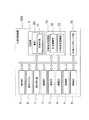
[孔版印刷装置の構成]
図1に示すように、孔版印刷装置100は、制御部9、操作パネル8、読み取り部1、製版部2、着版部3、排版部4、給紙部5、排紙部6、印刷部7、印刷条件調整部75、外部インタフェース部74等を備える。
【0019】
制御部9は、図示しない処理装置(CPU)、RAM、ROM、記憶手段(例えばハードディスク)等で構成され、処理装置はROMや記憶手段に記憶されたプログラムやデータをRAMに読み出して処理し、処理結果に基づいて印刷装置全体を制御する。
【0020】
外部インタフェース部74は、孔版印刷装置100がネットワーク等を介して他装置と接続するための機能を有する。
【0021】
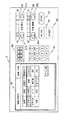
操作パネル8は、ユーザとのインタフェースを実現するため孔版印刷装置100の上部に配置され、図4に例示するように、ユーザによる原稿の種類、印刷モード(製版条件)等の設定やユーザへの情報等を表示する液晶タッチパネル85、印刷枚数等を設定するテンキー81、製版/印刷開始を指示するSTARTキー82、製版/印刷停止を指示するSTOPキー83、設定された印刷枚数等を表示する表示部84が設けられている。
【0022】
さらに、操作パネル8は、印刷濃度を設定する印刷濃度設定キー87a,87b及び設定された印刷濃度を表示する印刷濃度表示部86、印刷速度を設定する印刷速度設定キー89a,89b及び設定された印刷速度を表示する印刷速度表示部88、試し刷りを指示する試し刷りキー90等が設けられている。
【0023】
製版/印刷する場合は、液晶タッチパネル85の右上角に表示される製版/印刷ボタンを操作(タッチ)すると、「製版」「印刷」が順次設定される。例えば「製版」に設定すると、図4に例示する設定画面が液晶タッチパネル85に表示され、原稿の種類、変倍、印刷モード、用紙サイズ等の各種選択ボタンを操作することで所望の条件に設定され、STARTキー82を操作すると製版が開始される。製版が終了すると、液晶タッチパネル85の左上角に表示される表示ボタンに「印刷できます」と表示される。
【0024】
また、製版/印刷ボタンを操作して「印刷」に設定すると、図5に例示する設定画面が液晶タッチパネル85に表示される。必要に応じて所望の条件を設定し、STARTキー82を操作すると製版が開始される。さらに具体的には、印刷モードを「省インク」に設定すると、印刷条件は予め設定し制御部9のROM等に記憶された省インクの標準的な印刷濃度、印刷速度を、印刷濃度表示部86、印刷速度表示部88に表示する。ユーザは印刷濃度設定キー87a,87b及び印刷速度設定キー89a,89bを操作して設定値を変更することもできる。
【0025】
再度図1に戻って、版胴26に記憶手段71を設け、孔版原紙18が着版部3により着版された時、ユーザにより設定された印刷モード(製版条件)、印刷条件を記憶手段71に記憶する。そして、印刷開始が指示されると、記憶手段71に記憶した印刷モード、印刷条件を参照し、参照した印刷条件に印刷条件調整部75を調整して、印刷部7は印刷を実行する。
【0026】
印刷条件調整部75は、印刷濃度を調整する印圧調整部72と、印刷速度を調整する印刷速度調整部73により構成される。より具体的には、印刷濃度は印圧調整部72によるプレスローラ140の版胴26への押圧力を、ユーザにより設定された印刷濃度に対応する押圧力に調整し、印刷速度は印刷速度調整部73によるドラム駆動モータ25の回転速度(版胴26の回転速度)を、ユーザにより設定された印刷速度(印刷モードに対応する印刷速度)に調整する。なお、印刷濃度と押圧力、印刷速度と版胴26の回転数の変換値は、制御部9のROM等に予め記憶されている。
【0027】
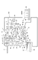
図2に示すように、読み取り部1は、印刷すべき原稿が載置される原稿セット台10、原稿セット台10上の原稿の有無を検出する反射型の原稿センサ11,12、原稿セット台10の原稿を搬送する原稿搬送ロール対13,14、原稿搬送ロール対13,14を回転駆動するステッピングモータ15、原稿搬送ロール対13,14によって搬送される原稿の画像を光学的に読み取り、これを電気信号に変換する密着型のイメージセンサ16、原稿セット台10より排出される原稿を載置する原稿排出トレー17などを有する。原稿セット台10に載置された原稿は原稿搬送ロール対13,14によって搬送され、搬送された原稿の画像をイメージセンサ16が読み取る。
【0028】
製版部2は、ロールされた長尺状の孔版原紙18を収容する原紙収容部19、原紙収容部19の搬送下流に配置されたサーマルヘッド20、サーマルヘッド20の対向位置に配置されたプラテンロール21、プラテンロール21及びサーマルヘッド20の搬送下流に配置された原紙送りロール対22、プラテンロール21及び原紙送りロール対22を回転駆動するライトパルスモータ23、原紙送りロール対22の搬送下流に配置された原紙カッタ24などを有する。プラテンロール21と原紙送りロール対22の回転により長尺状の孔版原紙18を搬送し、イメージセンサ16で読み取られた画像データに基づきサーマルヘッド20により、孔版原紙18を感熱穿孔して製版し、製版された孔版原紙18を所定長さに原紙カッタ24で切断する。
【0029】
着版部3は、版胴26の外周面に設けられ、孔版原紙18の先端をクランプする原紙クランプ部27、版胴26の検出片28aを検出することによって版胴26の外周面に孔版原紙18が着版されているか否かを検出する原紙確認センサ28などを有する。
【0030】
印刷部7は、外周部分が多孔構造によるインク通過性の部材で構成され、ドラム駆動モータ25の駆動力によって図1のA矢印方向に回転する版胴26、版胴26の検出片29を検出することによって版胴26の基準位置を検出する基準位置検出センサ30、ドラム駆動モータ25の回転を検出するロータリエンコーダ31などを有する。基準位置検出センサ30の検出出力を基にロータリエンコーダ31の出力パルスを検出することによって、版胴26の回転位置を検出することができる。ドラム駆動モータ25は、印刷速度調整部73により制御される。
【0031】
また、印刷部7は、版胴26の内部に配置されたスキージロール32、スキージロール32に近接配置されたドクターロール33を有し、スキージロール32とドクターロール33とで囲まれた外周スペースにインク34が溜められている。回転するスキージロール32の外周に付着するインク34がドクターロール33との隙間を通ることで、スキージロール32には所定膜厚のインク34のみが付着され、この所定膜厚のインク34が版胴26の内周面に供給される。
【0032】
さらに、印刷用紙37を版胴26に押し付けるプレスローラ140およびプレスローラ140は、印圧調整部72により版胴26の回転に同期して駆動される。
【0033】
そして、製版部2から搬送される孔版原紙18の先端を原紙クランプ部27でクランプし、このクランプした状態で版胴26が回転されて孔版原紙18が版胴26の外周面に着版され、版胴26の回転に同期して給紙部5より搬送される印刷用紙37をプレスローラ140で版胴26に着版された孔版原紙18に押圧することによって孔版原紙18の穿孔からインク34が印刷用紙37に転写されて原稿の画像が印刷される。
【0034】
給紙部5は、印刷用紙37が載置される給紙台38、給紙台38から最上位置の印刷用紙37のみを搬送させる1次給紙ロール39,40、1次給紙ロール39,40によって搬送された印刷用紙37を版胴26の回転に同期して版胴26とプレスローラ140の間に搬送する2次給紙ロール対41、2次給紙ロール対41間に印刷用紙37が搬送されたか否かを検出する給紙センサ42などを有する。1次給紙ロール39,40には給紙クラッチ43を介してドラム駆動モータ25の回転が選択的に伝達されるように構成されている。
【0035】
排紙部6は、印刷処理された印刷用紙37を版胴26から分離する用紙分離爪44、用紙分離爪44により版胴26から剥離された印刷用紙37が搬送される搬送通路45、搬送通路45より排紙される印刷用紙37が載置される排紙台46などを有する。排紙台46には、サイドフェンス59,60とエンドフェンス61が設けられている。
【0036】
排版部4は、版胴26に着版された孔版原紙18を引き剥がしながら搬送する排版搬送ロール対47、排版搬送ロール対47を回転駆動する排版モータ48、排版搬送ロール対47により搬送されて来る孔版原紙18を収納する排版ボックス49、排版搬送ロール対47により搬送されてくる孔版原紙18が排版ボックス49に搬送されたか否かを検出する排版センサ50などを有する。
【0037】
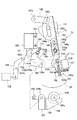
図3に印圧調整部72の詳細な構成例を示す。
【0038】
図3に示すように、版胴26の中心軸120cには、版胴26と一体に回転するカム141が取り付けられており、カム141には一端を軸142aによって枢支されたカムフォロワレバー142が係合している。カムフォロワレバー142は、図示されていないばねによって図3において下方へ付勢され、他端を軸142bによりレバー要素143と枢動連結されている。
【0039】
レバー要素143は、軸142bによってカムフォロワレバー142と直接連結された第1のレバー要素144と、パルスモータ150および減速機構151を設けられた第2のレバー要素145とにより構成されている。
【0040】
第1のレバー要素144には第2のレバー要素145が摺動するコの字形断面の摺動溝144bが設けられ、この摺動溝144bに案内されて第1のレバー要素144、第2のレバー要素145は、各レバー要素の長手方向に互いに伸縮自在とされている。第2のレバー要素145には長孔146aが形成され、第1のレバー要素144に取り付けられた係合端子146が長孔146aに係合していることにより、第1のレバー要素144、第2のレバー要素145は最大伸縮量を規定されている。
【0041】
また第1のレバー要素144には、カム141の回転によってレバー要素143全体が上下動し得るよう、中心軸120cを逃がす長孔144aが設けられている。
【0042】
第2のレバー要素145の下端部には支持板部147が折曲形成されており、この支持板部147にパルスモータ150とパルスモータ150の出力を減速する減速機構151とが設けられている。
【0043】
パルスモータ150の出力軸にはギア150aが取り付けられ、ギア150aには当該ギア150aと共に減速機構151を構成する大径ギア152が噛み合っている。大径ギア152の中心部には、ねじを切られた制御棒153が螺合する貫通孔152aが設けられ、パルスモータ150の回転は、ギア150aと大径ギア152との噛合により減速され、ねじ係合により制御棒153の中心軸方向の運動に変換される。
【0044】
制御棒153の一端には引張コイルばね154の一端が係止され、引張コイルばね154は、他端にて第1のレバー要素144に固定されたピン155に係止され、第2のレバー要素145を第1のレバー要素144に対し図3にて上方へ付勢している。
【0045】
なお、第2のレバー要素145にはピン155が挿通される長孔155aが形成されている。
【0046】
第2のレバー要素145には軸156bにより揺動レバー156の一端が連結され、揺動レバー156は中間部を図示されていない機枠より軸156aによって回動可能に枢支されている。軸156aには連結板157と連結レバー193の一端が同軸固定され、連結板157には回転軸159aによりプレスローラ140を回転可能に支持したブラケット159が連結部材158により取り付けられている。
【0047】
図示されていない機枠には振動減衰作用を行うダンパ196がねじ197により固定されており、ダンパ196のプランジャ191には軸191aによりフックレバー192の中間部と連結レバー193の他端が各々回動可能に取り付けられている。
【0048】
フックレバー192の下端部にはL字状に折曲された係合部192aが設けられ、揺動レバー156の端部には係合部192aに係脱可能に係合する突起156cが設けられている。これにより揺動レバー156の図3にて反時計廻り方向の回動に関し、揺動レバー156と連結レバー193とが選択的に駆動連結される。
【0049】
なお、連結レバー193の図3にて時計廻り方向の最大回動量、換言すればプレスローラ140の最大離間位置は支持部材172に螺合したアジャストスクリュ171により調節可能に設定される。
【0050】
フックレバー192は、図示されていないばねにより、図3にて時計廻り方向、即ち揺動レバー156との係合より離れる方向へ付勢されている。
【0051】
図示されていない機枠には枢軸194aによりプランジャレバー194が回動可能に取り付けられており、プランジャレバー194は、ソレノイド198により図3にて時計廻り方向へ選択的に回動駆動され、フックレバー192を、図3にて反時計廻り方向、即ち揺動レバー156との係合方向へ回動させる。
【0052】
これによりソレノイド198のオン動作によって揺動レバー156と連結レバー193とが駆動連結される。
【0053】
監視センサ195はプレスローラ140の位置を監視する。
【0054】
カム141が図3に示された回転位置にあるときは、レバー要素143は全体として下方位置にあり、プレスローラ140が、図3に示されている如く、版胴26より離れた離間位置にある。
【0055】
この状態よりドラム駆動モータ25の駆動により中心軸120cが図3にて反時計廻り方向へ180度回転されると、カム141も180度回転し、レバー要素143は全体的に上方に移動され、揺動レバー156が軸156aを中心として図3にて反時計廻り方向へ回転されることになる。
【0056】
このとき、ソレノイド198が引かれ、フックレバー192の係合部192aと揺動レバー156の突起156cとが係合した状態であると、揺動レバー156の回動がフックレバー192を介して連結レバー193に伝達され、これにより軸156aが図3にて反時計廻り方向へ回動され、プレスローラ140が、版胴26の外周面を押圧する方向、即ちプレス作用位置へ移動し、給紙された印刷用紙37を版胴26の外周面を押圧して、孔版印刷を行う。
【0057】
この際、プレスローラ140のプレス作用位置への移動は、第1のレバー要素144が引き上げられてこの動きが引張コイルばね154に引張力を与えつつ第2のレバー要素145に伝達され、揺動レバー156が軸156aを中心として図3にて反時計廻り方向へ回動することにより行われる。プレスローラ140が印刷用紙37を挟んで版胴26の外周面に対して押し付けられて揺動レバー156の軸156aを中心とした図3にて反時計廻り方向の回動が制限され、この状態よりなおも第1のレバー要素144が引き上げられることにより、第1のレバー要素144が第2のレバー要素145に対して変位し、引張コイルばね154が伸張する。この結果、引張コイルばね154の伸張によるばね力によりプレスローラ140が印刷用紙37を挟んで版胴26の外周面に対して押し付けられ、これにより押圧力はこのばね力により決まる。
【0058】
押圧力の調整に際しては、パルスモータ150を駆動して大径ギア152を回転させ、制御棒153の第2のレバー要素145における長手方向の位置を変化させる。これにより引張コイルばね154の取付長さが変化し、これに応じて引張コイルばね154の引張力が変化する。
【0059】
この引張コイルばね154の引張力の変化により、上述の如き作用下にてプレスローラ140を版胴26の外周面に対して押し付ける押圧力が変化する。
【0060】
[孔版印刷装置の処理動作]
次に、図6に示すフローチャートを参照して、本実施形態における孔版印刷装置100の処理動作について詳しく説明する。なお、以下に示す孔版印刷装置100の処理動作は、制御部9が孔版印刷装置100の各部を制御することにより実現される。
【0061】
ステップS01の処理において、制御部9は、製版、印刷の何れが選択されたかを判別する。製版が選択されたと判別した場合は処理をステップS02に進め、印刷が選択されたと判別した場合は処理をステップS31に進める。
【0062】
ステップS02の処理において、制御部9は、液晶タッチパネル85に原稿の種類、変倍、印刷モード、用紙サイズ等の製版設定画面を表示する(一例として図4)。
【0063】
ステップS03の処理において、ユーザは液晶タッチパネル85に表示された製版設定画面から原稿の種類、変倍、印刷モード、用紙サイズ等の条件を設定する。
【0064】
ステップS04の処理において、制御部9は、設定された設定内容を操作パネル8に表示する。印刷濃度や印刷速度は、設定された印刷モードに対応する標準的な設定値を、制御部9のROM等の記憶手段を参照して印刷濃度表示部86、印刷速度表示部88に表示するとともに、制御部9のRAMに記憶する。
【0065】
ユーザにより印刷濃度設定キー87a,87bや印刷速度設定キー89a,89bから標準的な設定値が修正された場合、制御部9は表示を変更し、RAMに記憶した設定値を書き換える。
【0066】
ステップS05の処理において、ユーザは原稿セット台10に原稿をセットし、テンキー81で印刷枚数を設定する。制御部9は、設定された印刷枚数を表示部84に表示する。
【0067】
ステップS06の処理において、制御部9は、STARTキー82により製版開始が指示されたか否かを判別する。制御部9は、製版開始が指示されたと判別した場合は処理をステップS07に進め、指示されていないと判別した場合は待機する。
【0068】
ステップS07の処理において、制御部9は、原稿セット台10に原稿がセットされているか否かを判別し、セットされていると判別した場合は処理をステップS08に進め、セットされていないと判別した場合は処理をステップS05に戻す。
【0069】
ステップS08の処理において、排版部4は、使用する版胴26に着版されている孔版原紙18を排版ボックス49に排版する。
【0070】
ステップS09の処理において、制御部9は、版胴26の記憶手段71に記憶されている排版された孔版原紙18の印刷モード、印刷条件をリセットし、処理をステップS10に進める。
【0071】
ステップS10の処理において、読み取り部1は、原稿セット台10にセットされた原稿の画像を読み取り、製版部2に送る。
【0072】
ステップS11の処理において、製版部2は、読み取り部1から送られた画像データを、制御部9のRAMに記憶された印刷モードに従って製版処理する。例えば、印刷モードが「省インク」の場合、孔版原紙18に穿孔する穿孔数を所定の方法で削減する等の製版処理を行う。
【0073】
ステップS12の処理において、着版部3は、製版部2から搬送された孔版原紙18を版胴26に着版する。
【0074】
ステップS13の処理において、制御部9は、制御部9のRAMに記憶した印刷モード、印刷条件を、ステップS12の処理で着版した版胴26の記憶手段71に記憶する。つまり、着版された孔版原紙18の印刷モード、印刷条件は版胴26の記憶手段71に記憶されている。
【0075】
ステップS14の処理において、制御部9は、製版が終了すると印刷設定画面を液晶タッチパネル85に表示する(一例として図5)。
【0076】
ステップS15の処理において、制御部9は、ユーザが印刷設定画面に従って設定する条件を設定し、STARTキー82により印刷開始が指示されたか否かを判別する。印刷開始が指示されたと判別した場合はステップS21に処理を進め、印刷開始が指示されないと判別した場合はステップS16に処理を進める。
【0077】
ステップS16の処理において、制御部9は、液晶タッチパネル85のドラム交換ボタンが操作されたか否かを判別する。ドラム交換ボタンが操作されたと判別した場合、制御部9は図示しない版胴26のドラムロックを解除し、ステップS17に処理を進める。ドラム交換ボタンが操作されないと判別した場合、制御部9は処理をステップS15に戻す。
【0078】
ステップS17の処理において、制御部9は、ユーザにより版胴26が交換されると処理を終了する。
【0079】
一方、ステップS15の処理において印刷開始が指示されたと判別した場合、ステップS21の処理において、制御部9は制御部9のRAMに記憶した印刷モード、印刷条件に従って、制御部9のROMに予め記憶されている印圧調整部72、印刷速度調整部73の調整値を参照する。そして、参照した調整値に基づいて印圧調整部72、印刷速度調整部73を制御し、プレスローラ140の押圧力や版胴26の回転数を調節する。
【0080】
ステップS22の処理において、給紙部5は、印刷用紙37を印刷部7に1枚給紙する。
【0081】
ステップS23の処理において、印刷部7は、給紙された印刷用紙37を、プレスローラ140により版胴26に着版された孔版原紙18に押圧するように搬送し、印刷用紙37にインク34を転写して印刷する。
【0082】
ステップS24の処理において、排紙部6は、印刷された印刷用紙37を排紙台46に排紙する。
【0083】
ステップS25の処理において、制御部9は、ユーザにより設定された印刷枚数の印刷を終了したか否かを判別する。設定された印刷枚数の印刷を終了していないと判別した場合は、処理をステップS22に戻す。設定された印刷枚数の印刷を終了したと判別した場合は、処理を終了する。
【0084】
他方、ステップS01の処理において印刷が選択されたと判別した場合、ステップS31の処理において、制御部9は、液晶タッチパネル85のドラム交換ボタンが操作されたか否かを判別する。ドラム交換ボタンが操作されたと判別した場合、制御部9は図示しない版胴26のドラムロックを解除し、処理をステップS32に進め、ドラム交換ボタンが操作されないと判別した場合、処理をステップS33に進める。
【0085】
ステップS32の処理において、ユーザが版胴26を交換する。
【0086】
ステップS33の処理において、制御部9は、交換された版胴26の記憶手段71に記憶されている孔版原紙18の印刷モード、印刷条件を参照して制御部9のRAMに記憶する。
【0087】
ステップS34の処理において、制御部9は、RAMに記憶した印刷モード、印刷条件を、操作パネル8の液晶タッチパネル85、印刷濃度表示部86及び印刷速度表示部88に表示する。
【0088】
ステップS35の処理において、ユーザが印刷枚数をテンキー81で設定する。制御部9は、設定された印刷枚数を表示部84に表示する。
【0089】
ステップS36の処理において、制御部9は、STARTキー82により印刷開始が指示されたか否かを判別する。制御部9は、印刷開始が指示されたと判別した場合、処理を先に説明したステップS21に進める。そして、以降の処理を順次実行する。一方、指示されていないと判別した場合は待機する。つまり、印刷に使用する版胴26に着版されている孔版原紙18の印刷モード、印刷条件に従って、同一条件で印刷できる。
【0090】
以上の説明から明らかなように、本実施形態による孔版印刷装置100によれば、製版された孔版原紙18が版胴26に着版されたときに、版胴26に設けられた記憶手段71にステップS03の処理で設定された印刷モード、印刷条件を記憶する。印刷開始が指示されると、記憶手段71に記憶した印刷モード、印刷条件に従って印刷条件調整部75を調整して印刷することができる。
【0091】
従って、製版処理と印刷処理を別々に実行する場合でも、印刷に使用する版胴26の記憶手段71に記憶した印刷モード、印刷条件に従って印刷できる。
【0092】
また、印刷に使用する版胴26が孔版印刷装置100に装着された時、版胴26の記憶手段71に記憶された製版条件及び印刷条件を表示手段(液晶タッチパネル85、印刷濃度表示部86、印刷速度表示部88)に表示し、印刷開始の指示に応じて、記憶手段71に記憶されている製版条件、印刷条件に従って印刷条件調整部75を調整して印刷することもできる。
【0093】
従って、複数の版胴26を交換しながら多色印刷するような場合でも、印刷に使用する版胴26の記憶手段71に記憶された印刷モード、印刷条件に従って印刷できる。
【0094】
それ故、ユーザは印刷に使用する版胴26に着版された孔版原紙18の印刷モード、印刷条件を記憶することや、印刷の都度印刷条件を調整設定することもなく、印刷に使用する版胴26の記憶手段71に記憶された印刷モード、印刷条件で印刷できるので、ユーザが所望する印刷物を容易に得ることができ、印刷の作業効率も向上する。
【0095】
さらに、印刷モード、印刷条件の設定内容を表示する表示手段(液晶タッチパネル85、印刷濃度表示部86、印刷速度表示部88)を備え、操作パネル8から設定された印刷モードや印刷条件だけでなく、印刷に使用する版胴26の記憶手段71に記憶した印刷モード、印刷条件についても表示手段に表示することで、製版処理と印刷処理を別々に実行する場合や、複数の版胴26を交換しながら多色印刷するような場合でも、ユーザは印刷に使用する版胴26の印刷モード、印刷条件を認識できる。
【0096】
以上、本発明の実施形態について詳細に説明したが、本発明は、その精神または主要な特徴から逸脱することなく、他の色々な形で実施することができる。
【0097】
例えば、本実施形態においては、読み取り部1で原稿を読み取らせて製版/印刷を行う孔版印刷装置100を例に説明したが、外部インタフェース部74からネットワーク等を介して他装置と接続し、原稿データ受信して製版/印刷を行う場合でも本実施形態と同様に実施することができる。
【0098】
従って、前述の実施例はあらゆる点で単なる例示に過ぎず、限定的に解釈してはならない。本発明の範囲は、特許請求の範囲によって示すものであって、明細書本文には何ら拘束されない。さらに、特許請求の範囲の均等範囲に属する変形や変更は、全て本発明の範囲内のものである。
【0099】
【発明の効果】
本発明によれば、製版処理と印刷処理を別々に実行する場合や、複数の版胴を交換しながら印刷を継続するような場合でも、印刷に使用する版胴に着版された孔版原紙の印刷モード、印刷条件に合致した条件で印刷することが可能な孔版印刷装置及び印刷方法を提供できる。
【図面の簡単な説明】
【図1】本実施の形態による孔版印刷装置の構成を例示するブロック図である。
【図2】図1に示す孔版印刷装置の製版/印刷処理部の構成を例示する概略構成図である。
【図3】図1に示す孔版印刷装置の印圧調整部の構成を例示する概略図である。
【図4】図1に示す孔版印刷装置の操作パネルを例示する概略図である。
【図5】図4に示す操作パネルの表示部の表示例を例示する概略図である。
【図6】図1に示す孔版印刷装置の製版/印刷処理の処理手順を例示するフローチャートである。
【符号の説明】
1…読み取り部
2…製版部
3…着版部
4…排版部
5…給紙部
6…排紙部
7…印刷部
8…操作パネル
9…制御部
10…原稿セット台
11,12…原稿センサ
13,14…原稿搬送ロール対
15…ステッピングモータ
16…イメージセンサ
17…原稿排出トレー
18…孔版原紙
19…原紙収容部
20…サーマルヘッド
21…プラテンロール
22…原紙送りロール対
23…ライトパルスモータ
24…原紙カッタ
25…ドラム駆動モータ
26…版胴
27…原紙クランプ部
28…原紙確認センサ
28a…検出片
29…検出片
30…基準位置検出センサ
31…ロータリエンコーダ
32…スキージロール
33…ドクターロール
34…インク
37…印刷用紙
38…給紙台
39,40…1次給紙ロール
41…2次給紙ロール対
42…給紙センサ
43…給紙クラッチ
44…用紙分離爪
45…搬送通路
46…排紙台
47…排版搬送ロール対
48…排版モータ
49…排版ボックス
50…排版センサ
59,60…サイドフェンス
61…エンドフェンス
71…記憶手段
72…印圧調整部
73…印刷速度調整部
74…外部インタフェース部
75…印刷条件調整部
81…テンキー
82…STARTキー
83…STOPキー
84…表示部
85…液晶タッチパネル
86…印刷濃度表示部
87a,87b…印刷濃度設定キー
89a,89b…印刷速度設定キー
88…印刷速度表示部
90…試し刷りキー
100…孔版印刷装置
120c…中心軸
140…プレスローラ
141…カム
142…カムフォロワレバー
142a…軸
142b…軸
143…レバー要素
144…第1のレバー要素
144a…長孔
144b…摺動溝
145…第2のレバー要素
146…係合端子
146a…長孔
147…支持板部
150…パルスモータ
150a…ギア
151…減速機構
152…大径ギア
152a…貫通孔
153…制御棒
154…引張コイルばね
155…ピン
155a…長孔
156…揺動レバー
156a…軸
156b…軸
156c…突起
157…連結板
158…連結部材
159…ブラケット
159a…回転軸
171…アジャストスクリュ
172…支持部材
191…プランジャ
191a…軸
192…フックレバー
192a…係合部
193…連結レバー
194…プランジャレバー
194a…枢軸
195…監視センサ
196…ダンパ
197…ねじ
198…ソレノイド[0001]
BACKGROUND OF THE INVENTION
The present invention relates to a stencil printing apparatus and printing method for executing plate making / printing according to printing conditions such as ink-saving printing.
[0002]
[Prior art]
In a stencil printing apparatus that performs printing by pressing a printing paper onto a stencil sheet that has been placed on a plate cylinder with a press roller, by variably setting printing conditions such as pressing force (printing pressure) and printing speed within a predetermined range, A stencil printing apparatus capable of printing at a desired printing density has been proposed by the present applicant (see, for example, Patent Document 1).
[0003]
With the technology described in
[0004]
[Patent Document 1]
Japanese Patent No. 2593923 [0005]
[Problems to be solved by the invention]
In a conventional stencil printing apparatus, ink-saving printing is realized by a method in which a user appropriately adjusts printing conditions such as pressing force and printing speed to vary the printing density. Therefore, when performing plate-making processing and printing processing separately, or when performing multicolor printing by sequentially replacing a plurality of plate cylinders, the printing conditions of the stencil sheet on the plate cylinder to be used are specified by the user. However, it is necessary to set printing conditions such as pressing force and printing speed based on the user's memory every time printing is performed. It is troublesome to set the printing conditions each time such printing, and there is a problem that the printing work efficiency is poor, such as a setting error caused by setting based on the user's memory.
[0006]
In order to respond to various requests from users in recent years, the stencil printing apparatus can select various types of printing such as ink-saving printing and high-quality printing in addition to standard printing.
[0007]
Such a wide variety of printing is realized by setting the platemaking conditions and the printing conditions in a predetermined relationship, and the platemaking of the stencil sheet that has been put on the plate cylinder used for printing is no longer a user's memory. It is extremely difficult to set the conditions and printing conditions for each printing.
[0008]
The present invention has been made in view of the situation as described above. When performing plate making processing and printing processing separately, or when performing multicolor printing while replacing a plurality of plate cylinders, printing is performed. It is an object of the present invention to provide a stencil printing apparatus and a printing method capable of printing based on a stencil sheet making condition and printing conditions of a stencil sheet attached to a used plate cylinder.
[0009]
[Means for Solving the Problems]
The features of the stencil printing apparatus according to the present invention are: a setting means for a user to set plate making conditions and printing conditions in order to obtain a desired printed matter; a plate making unit for making a stencil sheet under the set plate making conditions; A stencil printing apparatus comprising: a plate-making unit that forms the stencil sheet on a plate cylinder; and a printing unit that has a printing condition adjustment unit and adjusts and prints to the set printing conditions. has a storage means, when the plate making has been the stencil sheet is Chakuban on the plate cylinder, the plate-making conditions of the stencil sheet, the stored print conditions in the storage means, in response to the print start instruction The printing condition adjusting unit is adjusted in accordance with the plate making conditions and the printing conditions for printing.
[0010]
Further, the printing method according to the present invention is characterized in that the user sets the platemaking conditions and the printing conditions from the setting means in order to obtain a desired printed matter, makes the stencil sheet with the set platemaking conditions, and makes the platemaking A stencil sheet is stenciled on a plate cylinder, and is printed by adjusting a printing condition adjustment unit to the set printing conditions, and when the stencil sheet is made on the plate cylinder, The plate making conditions and the printing conditions of the stencil sheet are stored in a storage means provided in the plate cylinder, and printing is performed by adjusting the printing condition adjusting unit according to the plate making conditions and the printing conditions in accordance with an instruction to start printing. There is.
[0011]
Here, the “plate-making conditions” set by the user correspond to “printing mode”, “ink-saving” for printing that suppresses ink consumption, “high-quality” for high-quality printing, and “standard” for standard printing. And so on. “Print condition” includes “print speed” and “print density” corresponding to the set print mode, and is adjusted by the print condition adjustment unit. The printing condition adjustment unit includes a printing speed adjustment unit that adjusts the printing speed as the number of rotations of the plate cylinder, and a printing pressure adjustment unit that adjusts the printing density as a pressing force of the press roller against the plate cylinder.
[0012]
According to such a configuration, when the user sets printing conditions such as ink saving, high image quality, standard printing mode and printing speed, printing density, and the like from the setting unit and instructs the start of plate making, the plate making unit performs stencil printing. The plate making corresponding to the printing mode set on the base paper is executed. When the stencil sheet on which the plate-making part has been made is plated on the plate cylinder, the printing mode and printing conditions of the stencil sheet deposited on the storage means provided in the plate cylinder are stored.
[0013]
When the user gives an instruction to start printing, the print condition adjustment unit is adjusted according to the set print mode and print conditions, and printing can be performed under print conditions that match the set print mode. .
[0014]
Further, when the plate cylinder used for printing is installed in the stencil printing apparatus, the printing condition adjustment unit is adjusted according to the printing mode and printing conditions stored in the storage means of the installed plate cylinder, and the printing unit performs printing. You can also
[0015]
According to such a configuration, even when performing the plate making process and the printing process separately, or when performing multicolor printing while exchanging a plurality of plate cylinders, they are stored in the storage means of the plate cylinder used for printing. Therefore, the user can easily obtain a printed matter desired by the user.
[0016]
Furthermore, a display means for displaying the printing mode and printing conditions set by the user is provided, and the printing mode and printing conditions stored in the storage means of the plate cylinder used for printing are displayed on the display means, so that the user Can recognize the printing mode and printing conditions of the stencil sheet that has been applied to the plate cylinder used for printing.
[0017]
DETAILED DESCRIPTION OF THE INVENTION
Hereinafter, embodiments of the present invention will be described in detail with reference to FIGS. 1 to 6. Throughout the drawings, the same or equivalent parts and components are denoted by the same or equivalent reference numerals, and the description thereof is omitted or simplified.
[0018]
[Configuration of stencil printing machine]
As shown in FIG. 1, the
[0019]
The
[0020]
The
[0021]
The
[0022]
Further, the
[0023]
In the case of plate making / printing, when the plate making / printing button displayed in the upper right corner of the liquid
[0024]
When the printing / printing button is operated to set “print”, a setting screen illustrated in FIG. 5 is displayed on the liquid
[0025]
Returning again to FIG. 1, the
[0026]
The printing
[0027]
As shown in FIG. 2, the
[0028]
The
[0029]
The
[0030]
The
[0031]
The
[0032]
Further, the
[0033]
Then, the front end of the
[0034]
The
[0035]
The
[0036]
The
[0037]
FIG. 3 shows a detailed configuration example of the printing
[0038]
As shown in FIG. 3, a
[0039]
The
[0040]
The
[0041]
The
[0042]
A
[0043]
A
[0044]
One end of the
[0045]
The
[0046]
One end of a
[0047]
A
[0048]
An engaging portion 192a bent in an L shape is provided at the lower end portion of the
[0049]
Note that the maximum amount of rotation of the connecting
[0050]
The
[0051]
A
[0052]
As a result, the
[0053]
The
[0054]
When the
[0055]
When the
[0056]
At this time, when the
[0057]
At this time, the movement of the
[0058]
In adjusting the pressing force, the
[0059]
Due to the change in the tensile force of the
[0060]
[Processing operation of stencil printing machine]
Next, the processing operation of the
[0061]
In the process of step S01, the
[0062]
In the processing of step S02, the
[0063]
In the process of step S03, the user sets conditions such as the document type, scaling, print mode, paper size, and the like from the plate making setting screen displayed on the liquid
[0064]
In the process of step S04, the
[0065]
When the user corrects the standard setting values from the print
[0066]
In
[0067]
In the process of step S06, the
[0068]
In the process of step S07, the
[0069]
In the processing of step S08, the
[0070]
In the process of step S09, the
[0071]
In the process of step S <b> 10, the
[0072]
In the process of step S <b> 11, the
[0073]
In the process of step S <b> 12, the plate-making
[0074]
In the process of step S13, the
[0075]
In the process of step S14, the
[0076]
In the processing of step S15, the
[0077]
In the process of step S16, the
[0078]
In the process of step S17, the
[0079]
On the other hand, if it is determined in step S15 that the start of printing has been instructed, in step S21, the
[0080]
In the process of step S <b> 22, the
[0081]
In the process of step S <b> 23, the
[0082]
In the process of step S <b> 24, the
[0083]
In the process of step S25, the
[0084]
On the other hand, if it is determined in step S01 that printing has been selected, in step S31, the
[0085]
In the process of step S32, the user replaces the
[0086]
In the process of step S33, the
[0087]
In the process of step S <b> 34, the
[0088]
In the process of step S <b> 35, the user sets the number of prints with the ten key 81. The
[0089]
In the process of step S <b> 36 , the
[0090]
As is apparent from the above description, according to the
[0091]
Therefore, even when the plate making process and the printing process are executed separately, printing can be performed according to the printing mode and printing conditions stored in the storage means 71 of the
[0092]
Further, when the
[0093]
Therefore, even when multicolor printing is performed while replacing a plurality of
[0094]
Therefore, the user does not memorize the printing mode and printing conditions of the
[0095]
In addition, display means (a liquid
[0096]
As mentioned above, although embodiment of this invention was described in detail, this invention can be implemented in other various forms, without deviating from the mind or main characteristics.
[0097]
For example, in the present embodiment, the
[0098]
Therefore, the above-mentioned Example is only an illustration in all the points, and must not be interpreted limitedly. The scope of the present invention is indicated by the claims, and is not restricted by the text of the specification. Further, all modifications and changes belonging to the equivalent scope of the claims are within the scope of the present invention.
[0099]
【The invention's effect】
According to the present invention, even when the plate-making process and the printing process are performed separately, or even when printing is continued while replacing a plurality of plate cylinders, the stencil sheet on the plate cylinder used for printing is printed. It is possible to provide a stencil printing apparatus and a printing method capable of printing under conditions that match the printing mode and printing conditions.
[Brief description of the drawings]
FIG. 1 is a block diagram illustrating the configuration of a stencil printing apparatus according to an embodiment.
FIG. 2 is a schematic configuration diagram illustrating the configuration of a plate making / printing processing unit of the stencil printing apparatus shown in FIG. 1;
3 is a schematic view illustrating the configuration of a printing pressure adjustment unit of the stencil printing apparatus shown in FIG.
4 is a schematic view illustrating an operation panel of the stencil printing apparatus shown in FIG. 1. FIG.
5 is a schematic view illustrating a display example of a display unit of the operation panel shown in FIG.
6 is a flowchart illustrating a processing procedure of plate making / printing processing of the stencil printing apparatus shown in FIG. 1; FIG.
[Explanation of symbols]
DESCRIPTION OF
Claims (5)
前記版胴は記憶手段を有し、製版された前記孔版原紙が前記版胴に着版された時に、前記孔版原紙の前記製版条件、前記印刷条件を前記記憶手段に記憶し、印刷開始の指示に応じて前記製版条件、前記印刷条件に従って前記印刷条件調整部を調整して印刷することを特徴とする孔版印刷装置。Setting means for setting plate-making conditions and printing conditions, plate-making unit for making stencil sheet under the set plate-making conditions, plate-making unit for making plate-making stencil sheet on plate cylinder, and printing condition adjustment unit A stencil printing apparatus comprising a printing unit that adjusts and prints to the set printing conditions.
The plate cylinder has a storage means, and when the stencil sheet is made on the plate cylinder, the plate making conditions and the printing conditions of the stencil sheet are stored in the storage means, and an instruction to start printing According to the stencil printing apparatus, the printing condition adjusting unit is adjusted according to the plate making conditions and the printing conditions to perform printing.
を特徴とする請求項1に記載の孔版印刷装置。The stencil printing apparatus according to claim 1, further comprising display means for displaying the plate making conditions and the printing conditions.
を特徴とする請求項2に記載の孔版印刷装置。When the plate cylinder used for printing is mounted on the stencil printing apparatus, the plate making conditions and the printing conditions stored in the storage unit of the plate cylinder are displayed on the display unit, and in response to an instruction to start printing The stencil printing apparatus according to claim 2, wherein the printing condition adjustment unit is adjusted according to the plate making conditions and the printing conditions stored in the storage unit.
製版された前記孔版原紙が前記版胴に着版された時に、前記孔版原紙の前記製版条件、前記印刷条件を前記版胴に設けた記憶手段に記憶し、印刷開始の指示に応じて前記製版条件、前記印刷条件に従って前記印刷条件調整部を調整して印刷することを特徴とする孔版印刷装置の印刷方法。The plate making conditions and printing conditions are set from the setting means, the stencil sheet is made under the set plate making conditions, the plate-making stencil sheet is made on the plate cylinder, and the printing condition adjusting unit is set to the set printing conditions. Is a printing method for adjusting and printing,
When the plate-making stencil sheet is placed on the plate cylinder, the plate-making conditions and the printing conditions of the stencil sheet are stored in a storage means provided in the plate cylinder, and the plate-making process is performed according to an instruction to start printing. A printing method for a stencil printing apparatus, wherein printing is performed by adjusting the printing condition adjustment unit according to conditions and the printing conditions.
を特徴とする請求項4に記載の印刷方法。When the plate cylinder used for printing is mounted on the stencil printing apparatus, the plate making conditions and the printing conditions stored in the storage unit of the plate cylinder are displayed on a display unit, and in response to an instruction to start printing The printing method according to claim 4, wherein printing is performed by adjusting the printing condition adjustment unit according to the plate making conditions and the printing conditions stored in the storage unit.
Priority Applications (2)
| Application Number | Priority Date | Filing Date | Title |
|---|---|---|---|
| JP2003032365A JP4380997B2 (en) | 2003-02-10 | 2003-02-10 | Stencil printing apparatus and printing method |
| US10/773,280 US6899024B2 (en) | 2003-02-10 | 2004-02-09 | Stencil printing method and apparatus including printing drum with data storage section for storing printing and stencil making conditions |
Applications Claiming Priority (1)
| Application Number | Priority Date | Filing Date | Title |
|---|---|---|---|
| JP2003032365A JP4380997B2 (en) | 2003-02-10 | 2003-02-10 | Stencil printing apparatus and printing method |
Publications (2)
| Publication Number | Publication Date |
|---|---|
| JP2004243527A JP2004243527A (en) | 2004-09-02 |
| JP4380997B2 true JP4380997B2 (en) | 2009-12-09 |
Family
ID=32820925
Family Applications (1)
| Application Number | Title | Priority Date | Filing Date |
|---|---|---|---|
| JP2003032365A Expired - Lifetime JP4380997B2 (en) | 2003-02-10 | 2003-02-10 | Stencil printing apparatus and printing method |
Country Status (2)
| Country | Link |
|---|---|
| US (1) | US6899024B2 (en) |
| JP (1) | JP4380997B2 (en) |
Families Citing this family (4)
| Publication number | Priority date | Publication date | Assignee | Title |
|---|---|---|---|---|
| JP4464621B2 (en) * | 2003-04-07 | 2010-05-19 | 理想科学工業株式会社 | Stencil printing apparatus and printing method |
| JP2005288946A (en) * | 2004-04-01 | 2005-10-20 | Riso Kagaku Corp | Printing apparatus and control method thereof |
| JP5272216B2 (en) * | 2006-12-12 | 2013-08-28 | 株式会社リコー | Stencil printing machine |
| CN113561625A (en) * | 2021-07-22 | 2021-10-29 | 佛山市顺德区容桂意达电子薄膜器件有限公司 | High-speed printing device and method for realizing personalized patterns based on electrostatic printing technology |
Family Cites Families (6)
| Publication number | Priority date | Publication date | Assignee | Title |
|---|---|---|---|---|
| US5323704A (en) * | 1992-07-30 | 1994-06-28 | Heidelberg-Harris Gmbh | Device for the identification of a flexible roller shell |
| JP3292535B2 (en) * | 1993-03-01 | 2002-06-17 | 理想科学工業株式会社 | Stencil printer and plate cylinder |
| JP2593623B2 (en) | 1993-06-29 | 1997-03-26 | 理想科学工業株式会社 | Stencil printing machine |
| US6123024A (en) * | 1998-01-15 | 2000-09-26 | Alpha Metals, Inc. | Stencil incorporating electronic tag |
| JP2002046334A (en) * | 2000-08-04 | 2002-02-12 | Riso Kagaku Corp | Stencil printing apparatus and printing drum of the apparatus |
| AUPR735201A0 (en) * | 2001-08-31 | 2001-09-20 | Reefdale Pty Ltd | Silk screen |
-
2003
- 2003-02-10 JP JP2003032365A patent/JP4380997B2/en not_active Expired - Lifetime
-
2004
- 2004-02-09 US US10/773,280 patent/US6899024B2/en not_active Expired - Lifetime
Also Published As
| Publication number | Publication date |
|---|---|
| JP2004243527A (en) | 2004-09-02 |
| US20040154483A1 (en) | 2004-08-12 |
| US6899024B2 (en) | 2005-05-31 |
Similar Documents
| Publication | Publication Date | Title |
|---|---|---|
| JP3190148B2 (en) | Stencil printing machine | |
| JP3779847B2 (en) | Stencil printing machine | |
| JP4380997B2 (en) | Stencil printing apparatus and printing method | |
| JPH11268390A (en) | Plate making and printing equipment | |
| JP4464621B2 (en) | Stencil printing apparatus and printing method | |
| US6513426B2 (en) | Stencil printing machine | |
| JP2593623B2 (en) | Stencil printing machine | |
| JP4236968B2 (en) | Energy saving stencil printing apparatus and energy saving printing method | |
| JP2625435B2 (en) | Stencil printing machine | |
| JP2526279B2 (en) | Stencil printer | |
| JP2746821B2 (en) | Stencil printing machine | |
| JP2001328335A (en) | Stencil printing machine | |
| JP2001162916A (en) | Stencil printing machine | |
| JP3672801B2 (en) | Printing device | |
| JP2965413B2 (en) | Stencil printing machine | |
| US6435084B1 (en) | Rotary type stencil printing machine | |
| JP2000313158A (en) | Stencil printing machine | |
| JP5023376B2 (en) | Printing apparatus and printing method | |
| JP2593622B2 (en) | Stencil printing machine | |
| JP2006062376A (en) | Stencil printing machine | |
| JP2002029131A (en) | Stencil printing machine | |
| JPH09142003A (en) | Screen printing method and apparatus | |
| JP2001347742A (en) | Stencil printing machine | |
| JP2004262128A (en) | Stencil process printing device | |
| JP2004262127A (en) | Stencil process printing device |
Legal Events
| Date | Code | Title | Description |
|---|---|---|---|
| A621 | Written request for application examination |
Free format text: JAPANESE INTERMEDIATE CODE: A621 Effective date: 20060116 |
|
| A977 | Report on retrieval |
Free format text: JAPANESE INTERMEDIATE CODE: A971007 Effective date: 20080917 |
|
| A131 | Notification of reasons for refusal |
Free format text: JAPANESE INTERMEDIATE CODE: A131 Effective date: 20080930 |
|
| A521 | Request for written amendment filed |
Free format text: JAPANESE INTERMEDIATE CODE: A523 Effective date: 20081128 |
|
| A131 | Notification of reasons for refusal |
Free format text: JAPANESE INTERMEDIATE CODE: A131 Effective date: 20090526 |
|
| A521 | Request for written amendment filed |
Free format text: JAPANESE INTERMEDIATE CODE: A523 Effective date: 20090610 |
|
| TRDD | Decision of grant or rejection written | ||
| A01 | Written decision to grant a patent or to grant a registration (utility model) |
Free format text: JAPANESE INTERMEDIATE CODE: A01 Effective date: 20090818 |
|
| A01 | Written decision to grant a patent or to grant a registration (utility model) |
Free format text: JAPANESE INTERMEDIATE CODE: A01 |
|
| A61 | First payment of annual fees (during grant procedure) |
Free format text: JAPANESE INTERMEDIATE CODE: A61 Effective date: 20090915 |
|
| FPAY | Renewal fee payment (event date is renewal date of database) |
Free format text: PAYMENT UNTIL: 20121002 Year of fee payment: 3 |
|
| R150 | Certificate of patent or registration of utility model |
Ref document number: 4380997 Country of ref document: JP Free format text: JAPANESE INTERMEDIATE CODE: R150 Free format text: JAPANESE INTERMEDIATE CODE: R150 |
|
| FPAY | Renewal fee payment (event date is renewal date of database) |
Free format text: PAYMENT UNTIL: 20121002 Year of fee payment: 3 |
|
| FPAY | Renewal fee payment (event date is renewal date of database) |
Free format text: PAYMENT UNTIL: 20131002 Year of fee payment: 4 |
|
| R250 | Receipt of annual fees |
Free format text: JAPANESE INTERMEDIATE CODE: R250 |
|
| R250 | Receipt of annual fees |
Free format text: JAPANESE INTERMEDIATE CODE: R250 |
|
| R250 | Receipt of annual fees |
Free format text: JAPANESE INTERMEDIATE CODE: R250 |
|
| R250 | Receipt of annual fees |
Free format text: JAPANESE INTERMEDIATE CODE: R250 |
|
| R250 | Receipt of annual fees |
Free format text: JAPANESE INTERMEDIATE CODE: R250 |
|
| R250 | Receipt of annual fees |
Free format text: JAPANESE INTERMEDIATE CODE: R250 |
|
| R250 | Receipt of annual fees |
Free format text: JAPANESE INTERMEDIATE CODE: R250 |
|
| R250 | Receipt of annual fees |
Free format text: JAPANESE INTERMEDIATE CODE: R250 |
|
| R250 | Receipt of annual fees |
Free format text: JAPANESE INTERMEDIATE CODE: R250 |
|
| R250 | Receipt of annual fees |
Free format text: JAPANESE INTERMEDIATE CODE: R250 |
|
| R250 | Receipt of annual fees |
Free format text: JAPANESE INTERMEDIATE CODE: R250 |
|
| EXPY | Cancellation because of completion of term |