EP0904812A1 - A training device - Google Patents
A training device Download PDFInfo
- Publication number
- EP0904812A1 EP0904812A1 EP98118153A EP98118153A EP0904812A1 EP 0904812 A1 EP0904812 A1 EP 0904812A1 EP 98118153 A EP98118153 A EP 98118153A EP 98118153 A EP98118153 A EP 98118153A EP 0904812 A1 EP0904812 A1 EP 0904812A1
- Authority
- EP
- European Patent Office
- Prior art keywords
- training device
- devices
- steering
- rails
- wheel
- Prior art date
- Legal status (The legal status is an assumption and is not a legal conclusion. Google has not performed a legal analysis and makes no representation as to the accuracy of the status listed.)
- Withdrawn
Links
Images


Classifications
-
- A—HUMAN NECESSITIES
- A63—SPORTS; GAMES; AMUSEMENTS
- A63B—APPARATUS FOR PHYSICAL TRAINING, GYMNASTICS, SWIMMING, CLIMBING, OR FENCING; BALL GAMES; TRAINING EQUIPMENT
- A63B69/00—Training appliances or apparatus for special sports
- A63B69/18—Training appliances or apparatus for special sports for skiing
- A63B69/182—Training appliances or apparatus for special sports for skiing for cross-country-skiing
-
- A—HUMAN NECESSITIES
- A63—SPORTS; GAMES; AMUSEMENTS
- A63B—APPARATUS FOR PHYSICAL TRAINING, GYMNASTICS, SWIMMING, CLIMBING, OR FENCING; BALL GAMES; TRAINING EQUIPMENT
- A63B21/00—Exercising apparatus for developing or strengthening the muscles or joints of the body by working against a counterforce, with or without measuring devices
- A63B21/0004—Exercising devices moving as a whole during exercise
-
- A—HUMAN NECESSITIES
- A63—SPORTS; GAMES; AMUSEMENTS
- A63B—APPARATUS FOR PHYSICAL TRAINING, GYMNASTICS, SWIMMING, CLIMBING, OR FENCING; BALL GAMES; TRAINING EQUIPMENT
- A63B22/00—Exercising apparatus specially adapted for conditioning the cardio-vascular system, for training agility or co-ordination of movements
- A63B22/20—Exercising apparatus specially adapted for conditioning the cardio-vascular system, for training agility or co-ordination of movements using rollers, wheels, castors or the like, e.g. gliding means, to be moved over the floor or other surface, e.g. guide tracks, during exercising
- A63B22/201—Exercising apparatus specially adapted for conditioning the cardio-vascular system, for training agility or co-ordination of movements using rollers, wheels, castors or the like, e.g. gliding means, to be moved over the floor or other surface, e.g. guide tracks, during exercising for moving a support element in reciprocating translation, i.e. for sliding back and forth on a guide track
- A63B22/203—Exercising apparatus specially adapted for conditioning the cardio-vascular system, for training agility or co-ordination of movements using rollers, wheels, castors or the like, e.g. gliding means, to be moved over the floor or other surface, e.g. guide tracks, during exercising for moving a support element in reciprocating translation, i.e. for sliding back and forth on a guide track in a horizontal plane
-
- A—HUMAN NECESSITIES
- A63—SPORTS; GAMES; AMUSEMENTS
- A63B—APPARATUS FOR PHYSICAL TRAINING, GYMNASTICS, SWIMMING, CLIMBING, OR FENCING; BALL GAMES; TRAINING EQUIPMENT
- A63B22/00—Exercising apparatus specially adapted for conditioning the cardio-vascular system, for training agility or co-ordination of movements
- A63B22/0025—Particular aspects relating to the orientation of movement paths of the limbs relative to the body; Relative relationship between the movements of the limbs
- A63B2022/0038—One foot moving independently from the other, i.e. there is no link between the movements of the feet
-
- A—HUMAN NECESSITIES
- A63—SPORTS; GAMES; AMUSEMENTS
- A63B—APPARATUS FOR PHYSICAL TRAINING, GYMNASTICS, SWIMMING, CLIMBING, OR FENCING; BALL GAMES; TRAINING EQUIPMENT
- A63B22/00—Exercising apparatus specially adapted for conditioning the cardio-vascular system, for training agility or co-ordination of movements
- A63B22/16—Platforms for rocking motion about a horizontal axis, e.g. axis through the middle of the platform; Balancing drums; Balancing boards or the like
Definitions
- the present invention relates to a training device for simulation of cross-country skiing on wheels.
- Roller skis are already known which have skis provided with two rollers and serve to simulate the classic cross-country skiing technique. While at Cross-country skiing the repelling happens with the help of wax, scales or climbing skins, the roller ski is set up on at least one roller Freewheel (backstop) prevented from turning backwards. This enables an almost powerless push off.
- kick scooters which are suspended on two wheels and have a lower footboard on which the user stands on one side. This leads to to a limp driving style that should be avoided.
- a sports device in the form of a skateboard is already known from EP 0 304 585, which has a front-mounted tilting or steering aid. Yet this sports device cannot be controlled with sufficient accuracy. It is difficult to use the Steering required weight distribution and simultaneous actuation of the Coordinate tipping aid.
- an apparatus for imitation skiing which includes an endless belt or chain that over runs at least two rollers mounted in a frame, one belt or Chain pair is provided for transmitting the foot movement of the skier.
- an exercise device is known from FR-2536665, which in a Frame has two longitudinally slidable foot support devices. The frame is stationary on the floor.
- US 3856321 known a device that allows an imitation of cross-country skiing.
- Two Elongated platform facilities are provided, each for accommodation serve a foot of a user.
- the platform facilities are with ground-contacting rollers or wheels and the frame on which the platform devices are stored also has two ski poles that can be angled together with the platform devices.
- the object of the present invention is therefore to provide a training device, which is a simulation of cross-country skiing with the device being steerable enables.
- the steering device preferably has a steering tube in which a steering rod is guided, the handlebar being connected on the bottom to at least one wheel is.
- the step devices are preferably mounted in rails and the steering tube is connected to the rails.
- the rails are particularly preferably straight educated. In this way, the guidance is simple and low-friction Pedal facilities specified.
- the rails are preferably connected by a cross member, the Steering tube is attached to a front cross member. This way, a created essentially rectangular frame that of the training device Stability there.
- incline the kick devices allow when cornering. This allows dynamic cornering Tilting of the kicking devices and the user can be carried out.
- the running boards are inclined, that the cross members are articulated to the rails. Thereby the frame can be moved and sheared in the form of a parallelogram. This ensures that the two treads together with assigned roles have the same inclination.
- the step devices are preferably pivotally attached to the rails. This allows an inclination of the frame without inclination Reaching step facilities.
- the rails can, for example, in the form of a Pipe or a rod and the treading devices are longitudinally displaceable and pivotally attached to it.
- the rails are in one piece in the form of a Carrier formed, which has opposite rail parts in which slides connected to the step devices slide. This makes material saved.
- the carrier which is preferably arranged centrally, supports in a cantilever fashion attached to its opposite (opposite) side surfaces Step equipment. This is also the problem of skewing simplified when cornering, since only one carrier has to be tilted.
- the step devices are preferably each connected to the Rollers connected, wherein a carriage on a connecting means slidably is stored. In this way, the carriage can be placed on the connecting means move, for example for the purpose of tilting the carrier and the step equipment.
- Spring devices are particularly preferred between slide and roll holder or between the step device and slide attached to provide the necessary cushioning.
- the handlebar is spaced two Connected wheels. This allows greater stability of the training device against tipping achieve in the front area.
- the two wheels are preferably arranged approximately at a distance from the treading devices. This enables a secure four-wheel support to be achieved.
- Each step device is preferably assigned two roles, at least one a roller can only be rotated in one direction. So at least one role is everyone Roller pairs equipped with a freewheel that provides a backstop. In this way, the user can easily repel himself.
- the two wheels are preferably aligned. This ensures a clean straight line guaranteed.
- the cross member or the carrier or the wheel holder is preferred connected to the handlebar by a rod. This will create an additional one Longitudinal stiffening of the training device achieved.
- the rods are formed in two parts are and the two rod parts are hinged together or telescopic are brought together. This results, for example, in a detachable and foldable connection so that the training device can be folded can.
- a rod is with a bearing, in particular ball bearings, on the steering device attached. As a result, the steering movement of the handlebar is not hindered.
- the roll holder is particularly preferably directly with the kick device connected.
- a direct connection is from Roll holder and kick device provided to the center of gravity of the device to lay down.
- the roll holder preferably has a cantilever which attaches to a holder is.
- the boom is particularly preferably rod-shaped and the holder is special preferably plate-shaped. This allows the boom in Fasten the cross direction on the roll holder.
- the holder preferably has two guide rods, which are in slide or roller bearings are guided, the slide or roller bearings attached to a slide are, which is guided on a rail. This allows the height and the Change the inclination of the rail depending on the curve position.
- the step devices are each equipped with telescopic devices connected, which lead the kick devices.
- the telescopic devices extend laterally articulated on the step device up to the steering device. During the longitudinal movement of the The telescopic rods are retracted and kicked in at an angle changed.
- the end of the telescopic devices are with one another or with the handlebar or connected to the steering device. This results in a sufficient precise guidance of the kicking devices, the entire training device is collapsible due to the flexibility of the attachment.
- a brake is preferably assigned to at least one kick device can be actuated by the user's foot and has a brake shoe which is intended to rest on a roll or the floor.
- a footboard of the step device pivoted and the brake shoe is tilted by the running board brought into contact with a role.
- Stops are preferably attached to the front and rear ends of each rail, which limit the track of the step devices and an external engagement position prevent the step equipment.
- the step devices are included pivotally mounted holding members connected to the sled are stored, the slides are guided in rails.
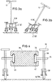
- the training device shown in the figures has according to the exemplary embodiments 1 to 3b two spaced rails 2, 4 made of stainless steel or aluminum, the ends of which are supported by two cross members 6, 8, also made of stainless steel.
- roller-mounted step devices 24, 26 are on the rails 2, 4 attached slidably.
- the bearing can be in the form of a roller bearing, i.e. Roller bearing or ball bearing, or be designed as a simple sliding axial bearing.
- the foot devices have a foot board for receiving a user's foot and optionally a fastening device therefor.
- the kicking device 24 is connected to two rollers 20, 22.
- the kick device 26 is connected with two rollers 16, 18.
- the rollers are used to support the training device on the floor and are movable in the longitudinal direction of the rails 2, 4. Instead of the wheels can also be wheels, for example with pneumatic tires.
- a steering tube 10 is attached vertically.
- Steering tube is a handlebar 12 provided with an upper steering bracket.
- the handlebar has a wheel holder with a at its lower end thereon axle-mounted wheel 14. This serves to support and steer the device.
- a roller is alternatively provided.
- the user stands on the two step devices 24, 26.
- By alternately pushing the feet forward and simultaneously Holding the handlebar 12 can set the exercise device in motion become.
- the use of cross-country shoes can be used provided with cross-country bindings provided on the step facilities be.
- the footboards feature footboards that have foot straps are provided to hold the user's boots or shoes.
- Kick device 24, 26 is connected to a braking device by a Foot of the user is actuated.
- FIG. 4 is an embodiment of the training device according to the invention shown with a one-piece carrier 38 which is on its opposite Side surfaces rail parts 40, 42 has. This is compared to the embodiments of Figures 1 to 3b material saved.
- Rail parts 40, 42 are slides, of which for Simplification, only one carriage 36 is described, which is in the rail part 42 slides.
- the carriage 36 has a plate-shaped sliding device, which with a rod-shaped holder 34 is connected.
- In the holder 34 is a recess provided with which the holder 34 on a rod-shaped or tubular Lanyard 30 slides.
- the connecting means 30 connects the step device 26 with the roll holder for the rolls 16, 18.
- FIG. 6 Preferred, as shown in Fig. 5, is Carriage 36 with its holder 34 on two connecting means 30, 32 without tilting stored.
- the two connecting means 30, 32 are fixed to the one above Kick device 26 connected. Furthermore, they are at their lower end firmly connected to the roll holder 28. Again, at least one role is everyone Provide roller pairs with a backstop to prevent the roller pair from pushing off to allow on the ground. Finally, there is a brake (not shown) provided that allows braking of the kick device.
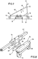
- FIGS. 7 and 8 A further embodiment of the invention is shown in FIGS. 7 and 8.
- a wheel holder 66 is provided, either directly at the rear end of a rail 62 or on a transverse cross member 6 (see Fig. 1) is attached.
- the wheel holder 66 carries a rear wheel 44 which aligned with the front wheel 14. This ensures that a flawless Straight running of the training device according to the invention takes place.
- the wheel 44 is at the same height as wheel 14. It will ensured that the two wheels are attached at such a height that the rollers 16, 18 of the treadmill without significant strain on the rail touch the ground.
- the wheel holder 66 or the Cross member 6 or the rear end of the rail 62 with an arrangement connected by rods 46, 48 which at their other end to the handlebar 12 are connected.
- the arrangement consists of two rod parts 46, 48, which are hinged together to provide a foldable arrangement.
- the Rod part 48 is fastened to the handlebar 12 with a ball bearing 50. Thereby proper steering of the handlebar 12 is ensured.
- the rods 46, 48 on their Fold in the joint.
- the handlebar 12 or the steering tube 10 or the rail 62 is designed to be foldable in order to be able to be folded ensure the entire device.
- the rod parts 46, 48 telescoped into each other.
- FIG. 8 shows a detail of the arrangement from FIG. 7 with the step device 26 shown in detail.
- the kick device 26 is directly on the roll holder 28 attached, and without intermediate parts.
- On the roll holder 28 is in the transverse direction a rod-shaped arm 54 attached, which in a plate-like Holder 56 ends at the end.
- the holder 56 in turn carries two guide rods 58, 58 '.
- These guide rods 58, 58 'slide in slide or roller bearings 60, 60', whereby the sliding or roller bearings 60, 60 'are attached to a carriage 64.
- Carriage 64 slides on the rail 62 Support of the rail 62 by the wheels 14, 44 a horizontal arrangement ensured.
- the height of the horizontal position is chosen so that the guide rods 58, 58 'in their central region from the slide or roller bearings 60, 60 'are performed.
- the guide rods 58, 58 ' move up or down in the bearings while the Carriage 64 inclined according to the position of the curve. This is a complication-free Enables the training device to corner.
- each step can be used only one role can be provided if there is sufficient tilting stability is ensured by the suspension of the step device.
- the rail 62 similar to Figure 4 can also be designed as a double rail with a one-piece carrier be when a one-piece carrier is preferred. In this case the order is 8 combined with the arrangement of Figure 4 and there are On both sides of the central support 38, a carriage 64 is arranged to be longitudinally displaceable.
- the treading devices are 24, 26 not guided in rails. Rather, the roller bearings Stepping devices 24, 26 connected at the end to telescopic devices. Of these, only the telescopic devices are to simplify the illustration described, which are connected to the step device 26.
- a telescopic rod 72 is articulated, which in one Telescopic cylinder 70 is guided.
- a telescopic rod 76 is pivotally articulated, which in a telescopic cylinder 74 is performed.
- the training device shown in FIG. 9 is shown in FIG shown folded state. The joints can be dismantled for this purpose.
- FIG. 11 shows a further embodiment of the training device according to the invention.
- the front part is formed similar to a commercial scooter with a handlebar 78, at the upper end of a handlebar 82 is attached.
- the handlebar 78 is guided in a steering tube 80 and at its other end connected to a fork 84 in which a wheel 86 is mounted.
- a support strut 88 is connected to the end with a hinge for folding of the device is designed.
- the mounting rail 90 is end, i.e. H. at its end opposite the wheel 86 a support device connected in the form of a support bracket 104 with it attached wheel 106 is formed.
- a rail for receiving a slide rod 92 or 108 is provided.
- This Slide rods 92, 108 are in the longitudinal direction to the support rail 90 in the rails movable.
- the slide rods 92 and 108 are in turn slidable with rails Carriage of slides 94 and 110 equipped. That way you can Carriage 94, 110 on the slide rods 92, 108 and this in the rails of the Slide mounting rail 90.
- This allows an extension of the leadership of the Reach car 110 over the end of the mounting rail 90 in the rearward direction. This is to achieve a particularly broad-step cross-country simulation sensible.
- carriages 94, 110 are omitted the slide rods are mounted directly in the rails of the mounting rail 90. This simplifies assembly and manufacture. In addition, to mount the mounting rail in a holder and with a toggle screw to determine the desired length.
- the holding members 96, 98 or 112, 114 are at their other ends on a wheel holder 100 or 116 attached, which carries a wheel 102 or 118 fixed to rest on the ground.
- the holding members 96, 98 and 112, 114 are for attachment to the wheel holder 100 or 116 hinged so that the mounting rail 90 are inclined can and the wheels by pivoting the holding members 96, 98 and 112, 114 raise and lower. In this way, the device is inclined for cornering or to compensate for uneven floors easily possible.
- Each wheel holder 100 or 116 has a braking device (not shown) on.
- a footboard of each wheel holder can be swiveled around the Stored longitudinally. With the running board there is one at a rear end Brake shoe connected to the system when the footboard is inclined one of the wheels 102, 118 arrives. This means that every wheel holder or step device can be used brake by lifting the foot.
- the training device according to the invention is distinguished from the State of the art in that it can be used without binding, no ski poles required and easy braking. Furthermore, there is no Boots must be put on and taken off. Balance problems can arise due to the convenient steering can be avoided. Significantly higher speeds are due to the symmetrical arrangement and consequently symmetrical Movement of the user possible.
Abstract
Offenbart wird eine Trainingsvorrichtung, die zwei Tritteinrichtungen aufweist, die mit bodenberührenden Rollen verbunden sind und im wesentlichen unabhängig voneinander längsverschieblich gelagert sind, und ein mit den Tritteinrichtungen gekoppeltes Lenkrohr aufweist, in dem eine Lenkstange geführt ist, wobei die Lenksstange bodenseitig mit mindestens einem Rad verbunden ist. Es sind in einer Ausführungsform Schienen vorgesehen, in denen die Tritteinrichtungen geführt sind. Alternativ sind Teleskopeinrichtungen zur Führung vorgesehen. <IMAGE>A training device is disclosed which has two treads, which are connected to rollers in contact with the ground and are mounted so as to be longitudinally displaceable essentially independently of one another, and a steering tube which is coupled to the treading means and in which a handlebar is guided, the handlebar being connected on the bottom to at least one wheel is. In one embodiment, rails are provided in which the step devices are guided. Alternatively, telescopic devices are provided for guidance. <IMAGE>
Description
Die vorliegende Erfindung betrifft eine Trainingsvorrichtung für die Simulation des Skilanglaufs auf Rollen.The present invention relates to a training device for simulation of cross-country skiing on wheels.
Es sind bereits Rollski bekannt, die mit zwei Rollen versehene Skier aufweisen und zur Simulation der klassischen Skilanglauftechnik dienen. Während beim Skilanglauf das Abstoßen mit Hilfe von Wachs, Schuppen oder Steigfellen geschieht, wird der Rollski mittels eines an mindestens einer Rolle eingerichteten Freilaufs (Rücklaufsperre) daran gehindert, sich nach hinten zu drehen. Dies ermöglicht ein nahezu kraftloses Abstoßen.Roller skis are already known which have skis provided with two rollers and serve to simulate the classic cross-country skiing technique. While at Cross-country skiing the repelling happens with the help of wax, scales or climbing skins, the roller ski is set up on at least one roller Freewheel (backstop) prevented from turning backwards. This enables an almost powerless push off.
Andererseits sind Trittroller bekannt, die an zwei Rädern aufgehängt sind und ein unteres Trittbrett aufweisen, auf dem der Benutzer einseitig steht. Dies führt zu einer hinkenden Fahrweise, die zu vermeiden ist.On the other hand kick scooters are known, which are suspended on two wheels and have a lower footboard on which the user stands on one side. this leads to to a limp driving style that should be avoided.
Aus der EP 0 304 585 ist bereits ein Sportgerät in Form eines Skateboards bekannt, das eine vorderseitig angebrachte Kipp- oder Lenkhilfe aufweist. Dennoch ist dieses Sportgerät nicht ausreichend genau steuerbar. Es ist schwierig, die zur Lenkung erforderliche Gewichtsverteilung und gleichzeitige Betätigung der Kipphilfe zu koordinieren.A sports device in the form of a skateboard is already known from EP 0 304 585, which has a front-mounted tilting or steering aid. Yet this sports device cannot be controlled with sufficient accuracy. It is difficult to use the Steering required weight distribution and simultaneous actuation of the Coordinate tipping aid.
Aus der DE-OS 24 54 976 ist bereits ein Apparat zum imitierten Skilaufen bekannt, welcher einen endlosen Riemen oder eine endlose Kette umfaßt, die über mindestens zwei in einem Rahmen gelagerte Rollen läuft, wobei ein Riemen- oder Kettenpaar zur Übertragung der Fußbewegung des Skiläufers vorgesehen ist. Ferner ist aus der FR-2536665 eine Übungsvorrichtung bekannt, die in einem Rahmen zwei längs verschieblich gelagerte Fußaufnahmeeinrichtungen aufweist. Der Rahmen steht stationär auf dem Boden. Schließlich ist aus der US-3856321 eine Vorrichtung bekannt, die eine Imitation des Skilanglaufs gestattet. Zwei langgestreckte Plattformeinrichtungen sind vorgesehen, die jeweils zur Aufnahme eines Fußes eines Benutzers dienen. Die Plattformeinrichtungen sind mit bodenkontaktierenden Rollen bzw. Rädern ausgestattet und der Rahmen, an dem die Plattformeinrichtungen gelagert sind, weist ferner zwei Ski-Stöcke auf, die zusammen mit den Plattformeinrichtungen abgewinkelt werden können.From DE-OS 24 54 976 an apparatus for imitation skiing is already known, which includes an endless belt or chain that over runs at least two rollers mounted in a frame, one belt or Chain pair is provided for transmitting the foot movement of the skier. Furthermore, an exercise device is known from FR-2536665, which in a Frame has two longitudinally slidable foot support devices. The frame is stationary on the floor. Finally, from US 3856321 known a device that allows an imitation of cross-country skiing. Two Elongated platform facilities are provided, each for accommodation serve a foot of a user. The platform facilities are with ground-contacting rollers or wheels and the frame on which the platform devices are stored also has two ski poles that can be angled together with the platform devices.
Aufgabe der vorliegenden Erfindung ist daher die Angabe einer Trainingsvorrichtung, die eine Simulation des Skilanglaufs bei sicherer Lenkbarkeit der Vorrichtung ermöglicht.The object of the present invention is therefore to provide a training device, which is a simulation of cross-country skiing with the device being steerable enables.
Dies wird erfindungsgemäß erreicht durch eine Trainingsvorrichtung gemäß Anspruch 1.This is achieved according to the invention by a training device according to claim 1.
Damit wird ein einfach aufgebautes und leicht bedienbares Fitnessgerät geschaffen, das sich durch eine kompakte Bauweise auszeichnet und eine gleitende dynamische Bewegung ermöglicht. Dabei sind die mit herkömmlichen Vorrichtungen verbundenen Gleichgewichtsprobleme vermieden. Auch ergibt sich nicht das Problem, für die Benutzung der Trainingsvorrichtung Stiefel an- und auszuziehen. Der Benutzer stellt sich auf die beiden Tritteinrichtung-en der Trainingsvorrichtung und hält sich zugleich an der Lenkstange fest. Durch Hin- und Herbewegung der Tritteinrichtungen kommt er in Fahrt, während er gleichzeitig mit der Lenkstange die Fährtrichtung steuern kann.This creates a simply constructed and easy-to-use fitness machine, which is characterized by a compact design and a sliding dynamic Enables movement. These are with conventional devices associated balance problems avoided. Nor does that result Problem of putting on and taking off boots when using the training device. The user stands on the two steps of the training device and holds onto the handlebar at the same time. Through reciprocation of the kicking equipment he gets going while he is using the handlebar can control the direction of travel.
Bevorzugt weist die Lenkeinrichtung ein Lenkrohr auf, in dem eine Lenkstange geführt ist, wobei die Lenkstange bodenseitig mit mindestens einem Rad verbunden ist. The steering device preferably has a steering tube in which a steering rod is guided, the handlebar being connected on the bottom to at least one wheel is.
Bevorzugt sind die Tritteinrichtungen in Schienen gelagert und das Lenkrohr ist mit den Schienen verbunden. Die Schienen sind besonders bevorzugt geradlinig ausgebildet. Auf diese Weise ist eine einfache und reibungsarme Führung der Tritteinrichtungen angegeben.The step devices are preferably mounted in rails and the steering tube is connected to the rails. The rails are particularly preferably straight educated. In this way, the guidance is simple and low-friction Pedal facilities specified.
Die Schienen sind bevorzugt durch einen Querträger verbunden, wobei das Lenkrohr an einem vorderen Querträger angebracht ist. Auf diese Weise wird ein im wesentlichen rechteckiger Rahmen geschaffen, der der Trainingsvorrichtung Stabilität gibt.The rails are preferably connected by a cross member, the Steering tube is attached to a front cross member. This way, a created essentially rectangular frame that of the training device Stability there.
Es sind Vorrichtungen vorgesehen, die eine Schrägstellung der Tritteinrichtungen bei Kurvenfahrt ermöglichen. Dadurch kann eine dynamische Kurvenfahrt bei Schrägstellung der Tritteinrichtungen und des Benutzers durchgeführt werden.Devices are provided that incline the kick devices allow when cornering. This allows dynamic cornering Tilting of the kicking devices and the user can be carried out.
In einer ersten Ausführungsform ist zur Schrägstellung der Trittbretter vorgesehen, daß die Querträger gelenkig mit den Schienen verbunden sind. Dadurch kann der Rahmen in Form eines Parallelogramms verschoben und geschert werden. Dabei ist sichergestellt, daß die beiden Tritteinrichtungen zusammen mit den zugeordneten Rollen dieselbe Neigung haben.In a first embodiment, the running boards are inclined, that the cross members are articulated to the rails. Thereby the frame can be moved and sheared in the form of a parallelogram. This ensures that the two treads together with assigned roles have the same inclination.
Die Tritteinrichtungen sind bevorzugt an den Schienen schwenkbar angebracht. Dadurch läßt sich ohne Schrägstellung des Rahmens eine Schrägstellung der Tritteinrichtungen erreichen. Die Schienen können beispielsweise in Form eines Rohres oder einer Stange ausgeführt sein und die Tritteinrichtungen sind längsverschieblich und schwenkbar daran angebracht.The step devices are preferably pivotally attached to the rails. This allows an inclination of the frame without inclination Reaching step facilities. The rails can, for example, in the form of a Pipe or a rod and the treading devices are longitudinally displaceable and pivotally attached to it.
In einer alternativen Ausführungsform sind die Schienen einstückig in Form eines Trägers ausgebildet, der gegenüberliegende Schienenteile aufweist, in denen mit den Tritteinrichtungen verbundene Schlitten gleiten. Dadurch wird Material eingespart. Der vorzugsweise zentral angeordnete Träger trägt auslegerartig an seinen gegenüberliegenden (abgewandten) Seitenflächen angebrachte schlittengeführte Tritteinrichtungen. Dadurch ist auch das Problem der Schrägstellung bei Kurvenfahrt vereinfacht, da lediglich ein Träger schräggestellt werden muß.In an alternative embodiment, the rails are in one piece in the form of a Carrier formed, which has opposite rail parts in which slides connected to the step devices slide. This makes material saved. The carrier, which is preferably arranged centrally, supports in a cantilever fashion attached to its opposite (opposite) side surfaces Step equipment. This is also the problem of skewing simplified when cornering, since only one carrier has to be tilted.
Die Tritteinrichtungen sind bevorzugt je durch ein Verbindungsmittel mit den Rollen verbunden, wobei ein Schlitten an einem Verbindungsmittel gleitverschieblich gelagert ist. Auf diese Weise läßt sich der Schlitten auf dem Verbindungsmittel verschieben, beispielsweise zum Zwecke der Schrägstellung des Trägers und der Tritteinrichtungen. Besonders bevorzugt sind Federeinrichtungen zwischen Schlitten und Rollenhalter bzw. zwischen Tritteinrichtung und Schlitten angebracht, um für die notwendige Abfederung zu sorgen.The step devices are preferably each connected to the Rollers connected, wherein a carriage on a connecting means slidably is stored. In this way, the carriage can be placed on the connecting means move, for example for the purpose of tilting the carrier and the step equipment. Spring devices are particularly preferred between slide and roll holder or between the step device and slide attached to provide the necessary cushioning.
Die Lenkstange ist in einer weiteren Ausführungsform mit zwei beabstandeten Rädern verbunden. Damit läßt sich eine größere Kippstabilität der Trainingsvorrichtung im vorderen Bereich erzielen.In another embodiment, the handlebar is spaced two Connected wheels. This allows greater stability of the training device against tipping achieve in the front area.
Bevorzugt sind die beiden Räder etwa im Abstand der Tritteinrichtungen angeordnet. Dadurch läßt sich eine sichere Vierrad-Auflage erzielen.The two wheels are preferably arranged approximately at a distance from the treading devices. This enables a secure four-wheel support to be achieved.
Bevorzugt sind jeder Tritteinrichtung zwei Rollen zugeordnet, wobei mindestens eine Rolle nur in einer Richtung drehbar ist. Somit ist mindestens eine Rolle jedes Rollenpaars mit einem Freilauf ausgerüstet, der eine Rücklaufsperre vorsieht. Auf diese Weise kann sich der Benutzer bequem abstoßen.Each step device is preferably assigned two roles, at least one a roller can only be rotated in one direction. So at least one role is everyone Roller pairs equipped with a freewheel that provides a backstop. In this way, the user can easily repel himself.
Bevorzugt ist an einem hinteren Querträger oder an einem hinteren Ende eines Trägers ein Radhalter mit einem zusätzlichen Rad befestigt. Dadurch läßt sich eine wirksame Abstützung der Schiene beziehungsweise Schienen im hinteren Bereich erzielen. Die Schiene beziehungsweise Schienen sind zwischen den beiden Rädern wirksam abgestützt. Is preferred on a rear cross member or at a rear end Carrier attached a wheel holder with an additional wheel. This allows effective support of the rail or rails in the rear Achieve range. The rail or rails are between the two Wheels supported effectively.
Bevorzugt fluchten die beiden Räder miteinander. Dadurch ist ein sauberer Geradeauslauf gewährleistet.The two wheels are preferably aligned. This ensures a clean straight line guaranteed.
Bevorzugt ist der Querträger oder der Träger beziehungsweise der Radhalter durch eine Stange mit der Lenkstange verbunden. Hierdurch wird eine zusätzliche Längsversteifüng der Trainingsvorrichtung erzielt.The cross member or the carrier or the wheel holder is preferred connected to the handlebar by a rod. This will create an additional one Longitudinal stiffening of the training device achieved.
In dieser Ausführungsform ist es bevorzugt, daß die Stangen zweiteilig ausgebildet sind und die beiden Stangenteile aneinander angelenkt sind oder teleskopartig ineinander geführt sind. Dadurch ergibt sich beispielsweise eine lösbare und klappbare Verbindung, so daß die Trainingsvorrichtung zusammengelegt werden kann.In this embodiment, it is preferred that the rods are formed in two parts are and the two rod parts are hinged together or telescopic are brought together. This results, for example, in a detachable and foldable connection so that the training device can be folded can.
Eine Stange ist mit einem Lager, insbesondere Kugellager, an der Lenkeinrichtung befestigt. Dadurch ist die Lenkbewegung der Lenkstange nicht behindert.A rod is with a bearing, in particular ball bearings, on the steering device attached. As a result, the steering movement of the handlebar is not hindered.
Der Rollenhalter ist besonders bevorzugt unmittelbar mit der Tritteinrichtung verbunden. In dieser Ausführungsform ist eine unmittelbare Verbindung von Rollenhalter und Tritteinrichtung vorgesehen, um den Schwerpunkt der Vorrichtung nach unten zu verlegen.The roll holder is particularly preferably directly with the kick device connected. In this embodiment, a direct connection is from Roll holder and kick device provided to the center of gravity of the device to lay down.
Der Rollenhalter weist bevorzugt einen Ausleger auf, der an einem Halter befestigt ist. Der Ausleger ist besonders bevorzugt stabförmig und der Halter besonders bevorzugt plattenförmig ausgebildet. Dadurch läßt sich der Ausleger in Querrichtung am Rollenhalter befestigen.The roll holder preferably has a cantilever which attaches to a holder is. The boom is particularly preferably rod-shaped and the holder is special preferably plate-shaped. This allows the boom in Fasten the cross direction on the roll holder.
Bevorzugt weist der Halter zwei Führungsstangen auf, die in Gleit- oder Rollenlagern geführt sind, wobei die Gleit- oder Rollenlager an einem Schlitten befestigt sind, der auf einer Schiene geführt ist. Dadurch läßt sich die Höhe und die Neigung der Schiene je nach Kurvenposition verändern. The holder preferably has two guide rods, which are in slide or roller bearings are guided, the slide or roller bearings attached to a slide are, which is guided on a rail. This allows the height and the Change the inclination of the rail depending on the curve position.
In einer weiteren Ausführungsform sind die Tritteinrichtungen jeweils mit Teleskopeinrichtungen verbunden, welche die Tritteinrichtungen führen. Die Teleskopeinrichtungen erstrecken sich angelenkt an der Tritteinrichtung seitlich aufwärts zur Lenkeinrichtung. Während der längsgerichteten Bewegung der Tritteinrichtungen werden die Teleskopstangen eingefahren und im Neigungswinkel verändert.In a further embodiment, the step devices are each equipped with telescopic devices connected, which lead the kick devices. The telescopic devices extend laterally articulated on the step device up to the steering device. During the longitudinal movement of the The telescopic rods are retracted and kicked in at an angle changed.
Die Teleskopeinrichtungen sind endseitig miteinander bzw. mit der Lenkstange oder dem Lenkeinrichtung verbunden. Dadurch ergibt sich eine ausreichend präzise Führung der Tritteinrichtungen, wobei die gesamte Trainingsvorrichtung aufgrund der Gelenkigkeit der Befestigung zusammenlegbar ist.The end of the telescopic devices are with one another or with the handlebar or connected to the steering device. This results in a sufficient precise guidance of the kicking devices, the entire training device is collapsible due to the flexibility of the attachment.
Bevorzugt ist mindestens einer Tritteinrichtung eine Bremse zugeordnet, die durch den Fuß des Benutzers betätigbar ist und eine Bremsbacke aufweist, die zur Anlage an einer Rolle bzw. dem Boden bestimmt ist.A brake is preferably assigned to at least one kick device can be actuated by the user's foot and has a brake shoe which is intended to rest on a roll or the floor.
In einer bevorzugten Ausführungsform ist ein Trittbrett der Tritteinrichtung schwenkbar gelagert und die Bremsbacke wird durch Schrägstellung des Trittbretts in Kontakt mit einer Rolle gebracht.In a preferred embodiment, a footboard of the step device pivoted and the brake shoe is tilted by the running board brought into contact with a role.
Bevorzugt sind am vorderen und hinteren Ende jeder Schiene Anschläge angebracht, die die Laufbahn der Tritteinrichtungen begrenzen und eine Außeneingriff-Stellung der Tritteinrichtungen verhindern.Stops are preferably attached to the front and rear ends of each rail, which limit the track of the step devices and an external engagement position prevent the step equipment.
In einer bevorzugten Ausführungsform sind die Tritteinrichtungen mit schwenkbar gelagerten Haltegliedern verbunden, die an Schlitten schwenkbar gelagert sind, wobei die Schlitten in Schienen geführt sind. In a preferred embodiment, the step devices are included pivotally mounted holding members connected to the sled are stored, the slides are guided in rails.
Weitere Vorteile, Merkmale und Anwendungsmöglichkeiten der vorliegenden
Erfindung ergeben sich aus der nachfolgenden Beschreibung mehrerer bevorzugter
Ausführungsbeispiele in Verbindung mit der Zeichnung.
Die in den Figuren gezeigte Trainingsvorrichtung weist gemäß den Ausführungsbeispielen
der Figuren 1 bis 3b zwei voneinander beabstandete Schienen 2,
4 aus Edelstahl oder Aluminium auf, die endseitig durch zwei Querträger 6, 8,
ebenfalls aus Edelstahl, verbunden sind. Dadurch ist ein rechteckiger Rahmen
gebildet. An den Schienen 2, 4 sind rollengelagerte Tritteinrichtungen 24, 26
gleitverschieblich befestigt. Die Lagerung kann in Form eines Wälzlagers, d.h.
Rollenlagers oder Kugellagers, oder als einfaches Gleitaxiallager ausgebildet sein.
Die Tritteinrichtungen weisen ein Trittbrett zur Aufnahme des Fußes eines Benutzers
und gegebenenfalls eine Befestigungseinrichtung dafür auf. Die Tritteinrichtung
24 ist mit zwei Rollen 20, 22 verbunden. Die Tritteinrichtung 26 ist
mit zwei Rollen 16, 18 verbunden. Die Rollen dienen zur Bodenauflage der Trainingsvorrichtung
und sind in Längsrichtung der Schienen 2, 4 beweglich. Anstelle
der Rollen kommen auch Räder, zum Beispiel mit Luftreifen in Betracht.The training device shown in the figures has according to the exemplary embodiments
1 to 3b two spaced
An dem vorderen Querträger 8 ist ein Lenkrohr 10 senkrecht befestigt. In dem
Lenkrohr ist eine mit einem oberen Lenkbügel versehene Lenkstange 12 aufgenommen.
Die Lenkstange hat an ihrem unteren Ende einen Radhalter mit einem
daran achsgelagerten Rad 14. Dies dient zur Auflage und Lenkung der Vorrichtung.
Anstelle des Rades ist alternativ eine Rolle vorgesehen.On the
In der in Fig. 2 gezeigten Stellung steht der Benutzer auf den beiden Tritteinrichtungen
24, 26. Durch abwechselndes Vorstoßen der Füße und gleichzeitiges
Festhalten der Lenkstange 12 kann die Trainingsvorrichtung in Bewegung gesetzt
werden. Für eine sportliche Fahrweise kann die Verwendung von Langlaufschuhen
mit auf den Tritteinrichtungen vorgesehenen Langlauf-Bindungen vorgesehen
sein. Die Tritteinrichtungen weisen Trittbretter auf, die mit Fußschlaufen
zur Halterung der Stiefel bzw. Schuhe des Benutzers versehen sind. Mit jeder
Tritteinrichtung 24, 26 ist eine Bremseinrichtung verbunden, die durch einen
Fuß des Benutzers betätigbar ist. In the position shown in FIG. 2, the user stands on the two
In dem Ausführungsbeispiel von Fig. 3a sind zwei Querträger 6, 6' sowie 8, 8'
zwischen den Schienen 2, 4 vorgesehen, die mit diesen gelenkig verbunden sind.
Auf diese Weise ergibt sich die Möglichkeit einer in Fig. 3b dargestellten Schrägstellung
der Trainingsvorrichtung für die Kurvenfahrt.In the embodiment of Fig. 3a, two
In Fig. 4 ist ein Ausführungsbeispiel der Trainingsvorrichtung gemäß der Erfindung
mit einem einstückigen Träger 38 gezeigt, der an seinen gegenüberliegenden
Seitenflächen Schienenteile 40, 42 aufweist. Damit wird gegenüber den Ausführungsformen
der Figuren 1 bis 3b Material eingespart. In den axial langgestreckten
Schienenteilen 40, 42 sind Schlitten aufgenommen, von denen zur
Vereinfachung nur ein Schlitten 36 beschrieben wird, der in dem Schienenteil 42
gleitet. Der Schlitten 36 weist eine plattenförmige Gleiteinrichtung auf, die mit
einem stabförmigen Halter 34 verbunden ist. In dem Halter 34 ist eine Ausnehmung
vorgesehen, mit der der Halter 34 auf einem stabförmigen oder rohrförmigen
Verbindungsmittel 30 gleitet. Das Verbindungsmittel 30 verbindet die Tritteinrichtung
26 mit dem Rollenhalter für die Rollen 16, 18. Bei Kurvenfahrt tritt
eine Verschiebung des Halters 34 längs des Verbindungsmittels 30 ein, und zwar
abwärts auf dem einen Verbindungsmittel und aufwärts an dem anderen Verbindungsmittel.
Dadurch kommt es zu einer Schrägstellung der Tritteinrichtungen
und des Trägers, wie in Fig. 6 gezeigt. Bevorzugt, wie in Fig. 5 gezeigt, ist der
Schlitten 36 mit seinem Halter 34 an zwei Verbindungsmitteln 30, 32 verkantungsfrei
gelagert. Die beiden Verbindungsmittel 30, 32 sind fest mit der obenliegenden
Tritteinrichtung 26 verbunden. Ferner sind sie an ihrem unteren Ende
fest mit dem Rollenhalter 28 verbunden. Wiederum ist mindestens eine Rolle jedes
Rollenpaars mit einer Rücklaufsperre versehen, um ein Abstoßen des Rollenpaars
am Erdboden zu ermöglichen. Schließlich ist eine (nicht gezeigte) Bremse
vorgesehen, die eine Abbremsung der Tritteinrichtung ermöglicht. 4 is an embodiment of the training device according to the invention
shown with a one-
In Figuren 7 und 8 ist eine weitere Ausführungsform der Erfindung gezeigt. Da
die Betätigung der Tritteinrichtungen in Längsrichtung auch zu einer Beanspruchung
der Schienen führt, ist in einer besonderen Ausführungsform zur endseitigen
Abstützung der Schiene ein Radhalter 66 vorgesehen, der entweder direkt
am hinteren Ende einer Schiene 62 oder an einem quergelagerten Querträger 6
(vergleiche Fig. 1) befestigt ist. Der Radhalter 66 trägt ein hinteres Rad 44, welches
mit dem vorderen Rad 14 fluchtet. Dadurch ist sichergestellt, daß ein einwandfreier
Geradeauslauf der erfindungsgemaßen Trainingsvorrichtung stattfindet.
Ferner befindet sich das Rad 44 in derselben Höhe wie Rad 14. Es wird
sichergestellt, daß die beiden Räder in einer derartigen Höhe befestigt sind, daß
die Rollen 16, 18 der Tritteinrichtung ohne wesentliche Belastung der Schiene
den Boden berühren.A further embodiment of the invention is shown in FIGS. 7 and 8. There
the actuation of the step devices in the longitudinal direction also to a stress
the rails leads is in a special embodiment to the end
Supporting the rail a
Zur weiteren Versteifung des Rahmens ist der Radhalter 66 beziehungsweise der
Querträger 6 beziehungsweise das hintere Ende der Schiene 62 mit einer Anordnung
von Stangen 46, 48 verbunden, die an ihrem anderen Ende mit der Lenkstange
12 verbunden sind. Die Anordnung besteht aus zwei Stangenteilen 46, 48,
die aneinander angelenkt sind, um eine klappbare Anordnung vorzusehen. Der
Stangenteil 48 ist mit einem Kugellager 50 an der Lenkstange 12 befestigt. Dadurch
ist eine einwandfreie Lenkung der Lenkstange 12 sichergestellt. Zur Einrichtung
einer klappbaren Anordnung lassen sich die Stangen 46, 48 an ihrem
Gelenk einklappen. Ferner ist die Lenkstange 12 beziehungsweise das Lenkrohr
10 beziehungsweise die Schiene 62 klappbar ausgebildet, um die Zusammenklappbarkeit
der gesamten Vorrichtung sicherzustellen. Alternativ sind die Stangenteile
46, 48 teleskopartig ineinander geführt.To further stiffen the frame, the
In Figur 8 ist ein Detail der Anordnung von Figur 7 mit der Tritteinrichtung 26
im Detail gezeigt. Die Tritteinrichtung 26 ist unmittelbar auf dem Rollenhalter
28 befestigt, und zwar ohne Zwischenteile. An dem Rollenhalter 28 ist in Querrichtung
ein stabförmiger Ausleger 54 angebracht, der in einem plattenartigen
Halter 56 endseitig endet. Der Halter 56 trägt seinerseits zwei Führungsstäbe 58,
58'. Diese Führungsstäbe 58, 58' gleiten in Gleit- oder Rollenlagern 60, 60', wobei
die Gleit- oder Rollenlager 60, 60' an einem Schlitten 64 befestigt sind. Der
Schlitten 64 gleitet auf der Schiene 62. Bei dieser Anordnung ist durch endseitige
Abstützung der Schiene 62 durch die Räder 14, 44 eine horizontale Anordnung
sichergestellt. Die Höhe der horizontalen Lage ist so gewählt, daß die Führungsstangen
58, 58' in ihrem mittleren Bereich von den Gleit- oder Rollenlagern 60,
60' geführt sind. Bei einer Kurvenlage können sich die Führungsstangen 58, 58'
in den Lagern aufwärts beziehungsweise abwärts bewegen, während sich der
Schlitten 64 entsprechend der Kurvenlage schrägstellt. Dadurch ist eine komplikationsfreie
Kurvenfahrt der Trainingsvorrichtung ermöglicht.FIG. 8 shows a detail of the arrangement from FIG. 7 with the
Alternativ zu der Verwendung von zwei oder mehr Rollen kann pro Tritteinrichtung
nur eine Rolle vorgesehen sein, wenn eine ausreichende Kippstabilität
durch die Aufhängung der Tritteinrichtung sichergestellt ist. Die Schiene 62
kann ähnlich Figur 4 auch als Doppelschiene mit einstückigem Träger ausgebildet
sein, wenn ein einstückiger Träger bevorzugt ist. In diesem Fall ist die Anordnung
nach Figur 8 mit der Anordnung nach Figur 4 kombiniert und es sind
auf beiden Seiten des Mittelträgers 38 je ein Schlitten 64 längsverschiebbar angeordnet.As an alternative to the use of two or more castors, each step can be used
only one role can be provided if there is sufficient tilting stability
is ensured by the suspension of the step device. The
In einer weiteren in Figur 9 und 10 gezeigten Ausführungsform sind die Tritteinrichtungen
24, 26 nicht in Schienen geführt. Vielmehr sind die rollengelagerten
Tritteinrichtungen 24, 26 endseitig mit Teleskopeinrichtungen verbunden.
Von diesen sind zur Vereinfachung der Darstellung nur die Teleskopeinrichtungen
beschrieben, die mit der Tritteinrichtung 26 verbunden sind. Am hinteren
Ende der Tritteinrichtung 26 ist eine Teleskopstange 72 angelenkt, die in einem
Teleskopzylinder 70 geführt ist. Am vorderen Ende der Tritteinrichtung 26 ist
eine Teleskopstange 76 schwenkbar angelenkt, welche in einem Teleskopzylinder
74 geführt ist. Die beiden Teleskopzylinder 70, 74 und die ihnen entsprechenden
Teleskopzylinder, die an der anderen Tritteinrichtung 24 befestigt sind, sind
entweder miteinander oder mit der Lenkstange 12 derart verbunden, daß eine
einwandfreie Geradeausführung der Tritteinrichtungen in Längsrichtung gewährleistet
ist. In Figur 10 ist die in Figur 9 gezeigte Trainingsvorrichtung in
zusammengeklapptem Zustand gezeigt. Zu diesem Zweck sind die Gelenke demontierbar.In a further embodiment shown in FIGS. 9 and 10, the treading devices are
24, 26 not guided in rails. Rather, the roller
Figur 11 zeigt eine weitere Ausführungsform der Trainingsvorrichtung gemäß
der Erfindung. Der vordere Teil ist ähnlich einem handelsüblichen Roller gebildet
mit einer Lenkstange 78, an deren oberem Ende ein Lenker 82 befestigt ist.
Die Lenkstange 78 ist geführt in einem Lenkrohr 80 und an ihrem anderen Ende
mit einer Gabel 84 verbunden, in der ein Rad 86 gehaltert ist. Mit dem Lenkrohr
ist eine Stützstrebe 88 verbunden, die endseitig mit einem Scharnier zur Zusammenlegung
des Geräts ausgebildet ist. An das Scharnier ist angeschlossen
eine Tragschiene 90, die sich über eine bestimmte Länge erstreckt. Die Tragschiene
90 ist endseitig, d. h. an ihrem dem Rad 86 gegenüberliegenden Ende mit
einer Stützeinrichtung verbunden, die in Form eines Stützhalters 104 mit daran
befestigtem Rad 106 ausgebildet ist. Auf beiden Seiten der Tragschiene 90 ist je
eine Schiene zur Aufnahme einer Gleitstange 92 bzw. 108 vorgesehen. Diese
Gleitstangen 92, 108 sind in Längsrichtung zur Tragschiene 90 in den Schienen
verschieblich. Die Gleitstangen 92 bzw. 108 sind ihrerseits mit Schienen zur verschieblichen
Aufnahme von Schlitten 94 bzw. 110 bestückt. Auf diese Weise können
Schlitten 94, 110 auf den Gleitstangen 92, 108 und diese in den Schienen der
Tragschiene 90 gleiten. Dadurch läßt sich eine Verlängerung der Führung des
Wagens 110 über das Ende der Tragschiene 90 in rückwärtiger Richtung erreichen.
Dies ist zur Erreichung einer besonders breitschrittigen Langlaufsimulation
sinnvoll. Alternativ (nicht gezeigt) sind die Schlitten 94, 110 unter Weglassung
der Gleitstangen unmittelbar in den Schienen der Tragschiene 90 gelagert.
Dadurch ist die Montage und Herstellung vereinfacht. Zusätzlich ist vorgesehen,
die Tragschiene in einem Halter verschieblich zu lagern und mit einer Knebelschraube
auf die gewünschte Länge festzustellen.FIG. 11 shows a further embodiment of the training device according to
the invention. The front part is formed similar to a commercial scooter
with a
An den Schlitten 94, 110 sind zwei voneinander beabstandete, stabförmige Halteglieder
96, 98 bzw. 112, 114 schwenkbar angelenkt. Die Halteglieder 96, 98
bzw. 112, 114 sind an ihren anderen Enden an einem Radhalter 100 bzw. 116
befestigt, der ein zur Auflage auf dem Boden befestigtes Rad 102 bzw. 118 trägt.
Die Halteglieder 96, 98 bzw. 112, 114 sind zur Befestigung am Radhalter 100
bzw. 116 schwenkbar angelenkt, so daß die Tragschiene 90 schräggestellt werden
kann und die Räder sich durch Verschwenkung der Halteglieder 96, 98 bzw. 112,
114 heben und senken lassen. Auf diese Weise ist eine Schrägstellung der Vorrichtung
für Kurvenfahrt bzw. ein Ausgleich von Bodenunebenheiten leicht
möglich. Jeder Radhalter 100 bzw. 116 weist eine (nicht gezeigte) Bremseinrichtung
auf. Zu diesem Zweck ist ein Trittbrett jedes Radhalters schwenkbar um die
Längsrichtung gelagert. Mit dem Trittbrett ist an einem hinteren Ende eine
Bremsbacke verbunden, die bei Schrägstellung des Trittbretts zur Anlage gegen
eines der Räder 102, 118 gelangt. Somit läßt sich jeder Radhalter bzw. jede Tritteinrichtung
durch Anhebung des Fußes bremsen.On the
Die Trainingsvorrichtung gemäß der Erfindung zeichnet sich gegenüber dem Stand der Technik dadurch aus, daß sie ohne Bindung benutzt werden kann, keine Skistöcke benötigt und ein leichtes Bremsen ermöglicht. Ferner ist kein An- und Ausziehen von Stiefeln notwendig. Gleichgewichtsprobleme können aufgrund der bequemen Lenkung vermieden werden. Deutlich höhere Geschwindigkeiten sind aufgrund der symmetrischen Anordnung und demzufolge symmetrischen Bewegung des Benutzers möglich.The training device according to the invention is distinguished from the State of the art in that it can be used without binding, no ski poles required and easy braking. Furthermore, there is no Boots must be put on and taken off. Balance problems can arise due to the convenient steering can be avoided. Significantly higher speeds are due to the symmetrical arrangement and consequently symmetrical Movement of the user possible.
Claims (15)
Applications Claiming Priority (4)
| Application Number | Priority Date | Filing Date | Title |
|---|---|---|---|
| DE19742626 | 1997-09-26 | ||
| DE19742626 | 1997-09-26 | ||
| DE19748215 | 1997-10-28 | ||
| DE19748215A DE19748215C1 (en) | 1997-09-26 | 1997-10-28 | Cross country ski training trolley |
Publications (1)
| Publication Number | Publication Date |
|---|---|
| EP0904812A1 true EP0904812A1 (en) | 1999-03-31 |
Family
ID=26040354
Family Applications (1)
| Application Number | Title | Priority Date | Filing Date |
|---|---|---|---|
| EP98118153A Withdrawn EP0904812A1 (en) | 1997-09-26 | 1998-09-24 | A training device |
Country Status (3)
| Country | Link |
|---|---|
| EP (1) | EP0904812A1 (en) |
| AU (1) | AU1026799A (en) |
| WO (1) | WO1999016516A1 (en) |
Cited By (1)
| Publication number | Priority date | Publication date | Assignee | Title |
|---|---|---|---|---|
| KR100606176B1 (en) * | 2003-10-01 | 2006-08-01 | 박경희 | Crank rocking propulsion vehicle |
Families Citing this family (1)
| Publication number | Priority date | Publication date | Assignee | Title |
|---|---|---|---|---|
| CA3012841C (en) * | 2016-02-05 | 2021-03-02 | Torque Fitness, Llc | Weight training sled |
Citations (8)
| Publication number | Priority date | Publication date | Assignee | Title |
|---|---|---|---|---|
| US3436088A (en) * | 1967-06-19 | 1969-04-01 | Maurice H Kunselman | Roller skis |
| US3856321A (en) | 1972-10-20 | 1974-12-24 | F Solymosi | Wheeled board toy assembly |
| DE2454976A1 (en) | 1974-11-19 | 1976-05-26 | Haakon Lie | APPARATUS FOR IMITATION OF SKIING |
| DE2830259A1 (en) * | 1978-07-10 | 1980-01-24 | Artur H Schmitt | Ski training vehicle - consists of tubular frame scooter driven by reciprocating sprung foot plates linked to rear wheels |
| FR2536665A1 (en) | 1982-11-30 | 1984-06-01 | Tekron Licensing Bv | EXERCISE MACHINE |
| GB2130900A (en) * | 1982-11-30 | 1984-06-13 | Tekron Licensing Bv | Exercise machine |
| EP0304585A1 (en) | 1987-08-27 | 1989-03-01 | Valentin Küttenbaum | Sporting device |
| US5338273A (en) * | 1993-01-27 | 1994-08-16 | Roadmaster Corporation | Quick change mechanism for synchronous/asynchronous exercise machine |
-
1998
- 1998-09-24 EP EP98118153A patent/EP0904812A1/en not_active Withdrawn
- 1998-09-24 WO PCT/EP1998/006104 patent/WO1999016516A1/en active Application Filing
- 1998-09-24 AU AU10267/99A patent/AU1026799A/en not_active Abandoned
Patent Citations (8)
| Publication number | Priority date | Publication date | Assignee | Title |
|---|---|---|---|---|
| US3436088A (en) * | 1967-06-19 | 1969-04-01 | Maurice H Kunselman | Roller skis |
| US3856321A (en) | 1972-10-20 | 1974-12-24 | F Solymosi | Wheeled board toy assembly |
| DE2454976A1 (en) | 1974-11-19 | 1976-05-26 | Haakon Lie | APPARATUS FOR IMITATION OF SKIING |
| DE2830259A1 (en) * | 1978-07-10 | 1980-01-24 | Artur H Schmitt | Ski training vehicle - consists of tubular frame scooter driven by reciprocating sprung foot plates linked to rear wheels |
| FR2536665A1 (en) | 1982-11-30 | 1984-06-01 | Tekron Licensing Bv | EXERCISE MACHINE |
| GB2130900A (en) * | 1982-11-30 | 1984-06-13 | Tekron Licensing Bv | Exercise machine |
| EP0304585A1 (en) | 1987-08-27 | 1989-03-01 | Valentin Küttenbaum | Sporting device |
| US5338273A (en) * | 1993-01-27 | 1994-08-16 | Roadmaster Corporation | Quick change mechanism for synchronous/asynchronous exercise machine |
Cited By (1)
| Publication number | Priority date | Publication date | Assignee | Title |
|---|---|---|---|---|
| KR100606176B1 (en) * | 2003-10-01 | 2006-08-01 | 박경희 | Crank rocking propulsion vehicle |
Also Published As
| Publication number | Publication date |
|---|---|
| WO1999016516A1 (en) | 1999-04-08 |
| AU1026799A (en) | 1999-04-23 |
Similar Documents
| Publication | Publication Date | Title |
|---|---|---|
| DE2518684C2 (en) | Device for locomotion of people whose legs have leg muscles that are too weak for free walking | |
| EP0392140B1 (en) | Steerable skate board | |
| DE10010852A1 (en) | Cleaning trolley for use in very large building; has at least one wheeled undercarriage and is connected to standing or seating device, e.g. scooter or monocycle | |
| EP0971836B1 (en) | Vehicle for gliding over the ground | |
| DE2621644A1 (en) | VEHICLE ARRIVED TRIPLE ON THE ROAD (CAMBERING VEHICLE) | |
| DE2925555A1 (en) | Scooter assembly with two rollers - has two parallel support units and binding devices to keep user's shoe in position | |
| DE3506026C2 (en) | ||
| DE19801672A1 (en) | Multi-gym training apparatus with rope-and-pulley operated weights | |
| EP1704901A1 (en) | Kickboard | |
| DE102006043558B4 (en) | Scooter-like collapsible sports equipment "mini" scooter | |
| DE19748215C1 (en) | Cross country ski training trolley | |
| DE19541966C2 (en) | Transportable walking aid | |
| EP0904812A1 (en) | A training device | |
| EP2004463B1 (en) | Vehicle, in particular sport and fun sport device | |
| EP2623391A2 (en) | Transport device for transporting a golf bag and at least one person | |
| DE202006014205U1 (en) | Collapsible mini roller scooter for pedestrian movement has extending steering assembly lockable in useful position and folding down to adjoin side of step board in non-use position | |
| DE102020000032A1 (en) | Coupling device and mobile walking aid for coupling a self-balancing vehicle | |
| AT501683B1 (en) | SKI-BOBBY SPORTS EQUIPMENT | |
| DE19546748A1 (en) | Escalator-accessible transport trolley | |
| EP0628465B1 (en) | Article of sport | |
| DE2730892A1 (en) | Ski run training machine - has sliding platforms operated by user's feet and can be folded flat when not in use | |
| AT409754B (en) | Sports equipment for mobility in alpine terrain | |
| DE2723107A1 (en) | Skateboard with detachable braking system - operated by two vertical hand-held pivot levers linked to pads contacting ground or front wheels | |
| EP1346900A1 (en) | Perambulator | |
| DE19704390A1 (en) | Foldaway training apparatus |
Legal Events
| Date | Code | Title | Description |
|---|---|---|---|
| PUAI | Public reference made under article 153(3) epc to a published international application that has entered the european phase |
Free format text: ORIGINAL CODE: 0009012 |
|
| AK | Designated contracting states |
Kind code of ref document: A1 Designated state(s): AT BE CH CY DE DK ES FI FR GB GR IE IT LI LU MC NL PT SE |
|
| AX | Request for extension of the european patent |
Free format text: AL;LT;LV;MK;RO;SI |
|
| AKX | Designation fees paid | ||
| REG | Reference to a national code |
Ref country code: DE Ref legal event code: 8566 |
|
| STAA | Information on the status of an ep patent application or granted ep patent |
Free format text: STATUS: THE APPLICATION IS DEEMED TO BE WITHDRAWN |
|
| 18D | Application deemed to be withdrawn |
Effective date: 19991001 |