EP0904810B1 - Vorrichtung zum amortisieren von Skistöcken, Stöcken für Ausflüge, Wanderstöcken, Krücken oder dergleichen - Google Patents
Vorrichtung zum amortisieren von Skistöcken, Stöcken für Ausflüge, Wanderstöcken, Krücken oder dergleichen Download PDFInfo
- Publication number
- EP0904810B1 EP0904810B1 EP98117977A EP98117977A EP0904810B1 EP 0904810 B1 EP0904810 B1 EP 0904810B1 EP 98117977 A EP98117977 A EP 98117977A EP 98117977 A EP98117977 A EP 98117977A EP 0904810 B1 EP0904810 B1 EP 0904810B1
- Authority
- EP
- European Patent Office
- Prior art keywords
- shock absorbing
- absorbing device
- rods
- amortization
- elastic
- Prior art date
- Legal status (The legal status is an assumption and is not a legal conclusion. Google has not performed a legal analysis and makes no representation as to the accuracy of the status listed.)
- Expired - Lifetime
Links
Images

Classifications
-
- A—HUMAN NECESSITIES
- A63—SPORTS; GAMES; AMUSEMENTS
- A63C—SKATES; SKIS; ROLLER SKATES; DESIGN OR LAYOUT OF COURTS, RINKS OR THE LIKE
- A63C11/00—Accessories for skiing or snowboarding
- A63C11/22—Ski-sticks
-
- A—HUMAN NECESSITIES
- A45—HAND OR TRAVELLING ARTICLES
- A45B—WALKING STICKS; UMBRELLAS; LADIES' OR LIKE FANS
- A45B9/00—Details
-
- A—HUMAN NECESSITIES
- A45—HAND OR TRAVELLING ARTICLES
- A45B—WALKING STICKS; UMBRELLAS; LADIES' OR LIKE FANS
- A45B9/00—Details
- A45B2009/002—Accessories
-
- A—HUMAN NECESSITIES
- A63—SPORTS; GAMES; AMUSEMENTS
- A63C—SKATES; SKIS; ROLLER SKATES; DESIGN OR LAYOUT OF COURTS, RINKS OR THE LIKE
- A63C2203/00—Special features of skates, skis, roller-skates, snowboards and courts
- A63C2203/20—Shock or vibration absorbing
Definitions
- the present invention relates to a device for amortizing the rods being used for skiing, for excursions, for walking, for crutches and similar articles.
- the rods are used to complete the motion of the legs following typically the cadence in a synchronous manner. Both these situations involve stresses of different nature and intensity which are transmitted to the limbs which maneuver the rods. Specifically in the ski practice when one goes downhill these stresses are typically short, of great intensity and relatively sporadic and irregular. On the contrary, in the practice of skiing at the bottom, the stresses result more prolonged and of lower intensity but with high frequency of repetition typically equal to the forward steps.
- This device provides similarly to the devices of known type the presence of two cylinders coaxially with the longitudinal axis of the structure to be amortized, one of the two cylinders being placed partially within the other, with the possibility of sliding with respect to the same in the presence of stresses which occur on the structure during use following the contact with the bearing surface and is characterized mainly by the fact that it utilizes an elastomer as the elastic means.
- An object of the present invention is to provide a device for the amortization of the rods and similar articles which is free of the drawbacks described hereinabove and which in particular is effective in the amortization action in both the two phases, that is the phase of compression followed by the phase of traction.
- the device of the present invention in addition to achieving an action of amortization of the impact of the rod with the ground in a manner to generate a feeling of comfort in the limb which performs the maneuver the following results are possible:
- the amortization action is further reinforced by providing that at least one of the two elastic means which are placed one opposite to the other has a dimension such that it may slide against the containing wall so that during the compression phase it operates as a typical friction piston.
- a good amortization device which offers constant elastic elements and suitably not linear, in addition to the use of an elastomer is achieved by using conical or bi-conical metallic springs.
- the maximal compactedness and light weight of the amortization device is achieved by using a single elastic element which operates both during the traction and during the compression phase and which is provided with a lock for stopping the shaft, the shaft being obtained with an elastomer of a foamed polyurethane of the type for instance commercially known under the names of CELLESTO or POLYCEL or with metallic springs of the type "bovolo" which means a twisting spring with conical helix and rectangular section or particular conical springs in lamination which require minimal space under equal excursion travels and which due to their particular constructive form may be obtained with an inherent amortization.
- the avoidance of the reciprocal rotation between the elements which constitute the rod and/or between the rod and the handle is achieved advantageously by providing that the central shaft offer a non-circular section so it is possible to transmit a twisting torque directly from the external cylinder to which it is anchored to the internal cylinder within which it slides without requiring the use of further guides or extensions such as in the known devices which negatively increase the space and this becomes particularly significant in telescopic rods in which there are several parts constituting the rod.
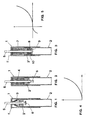
- the device of the invention contains schematically a first member (1) which in general is cylindrical and is disposed externally and by way of example could be made integral with the handgrip of the rod, the latter not being shown for simplicity reasons.
- a further element (2) which is also cylindrical and which has the possibility of sliding relatively to the first member in an essentially axial direction.
- the element (2) may be integral with that part of the rod which is intended to be effectively in contact with the bearing surface.
- an elastic hub is placed between the end plates (1') and (2') of member (1) and element (2) which are cylindrical, the end plates being opposite one to the other.
- the latter according to the first embodiment of the invention is constituted by a metallic spring (3) of the "bovolo" type while according to a second embodiment of the invention the elastic hub is constituted by elastomer (4). Both elastic hubs (3) and (4) are held in place by means of floating shaft (5) which is integral with end plate (1') and which goes over end plate (2').
- a first novel feature of the invention consists of providing that the two elastic hubs (3) and (4) described hereinabove have both bases of rest on the bearing surface firmly anchored to the corresponding end plates (1') and (2').
- a structure (6) which provides for the end of the course, this structure being applied to the end of the floating shaft (5), the latter being blocked on the base 2' according to manners which will be described hereinbelow.
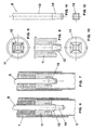
- Figs. 6-18 Several constructive means (6) for ending the course are shown in Figs. 6-18.
- the end plate (2') of element (2) is constituted by a hub (11) which is provided with tongues (12).
- the latter are flexible and during the compression conditions shown in Figure 6 they loosen coming in contact with body (13) of the floating shaft (5) but during the conditions of traction after the shaft reenters they provide to block the same becoming wedged in the tapered portion (14) which is formed in the end of the same shaft as shown in Figures 6 and 7.
- Figures 8 and 12 show in particular the constructive form of hub (11) and the end of the floating shaft (5).
- a second embodiment of the structure intended to achieve the end of the course which is used when it is required to have minimum space as shown in Figures 14 and 18 consists of providing the flexible tongues (15) totally contained in the interior of hub (16). Further these tongues engage in the interior of the longitudinal cavities (17) which are formed at the end of the body of the floating shaft (5).
- the location of the device along the rod does not matter from a functional point of view.
- the rod is used as a ski rod, however, it is preferable to make it integral with the handgrip because in this manner the effect of the device on the total inertia moment with respect to the wrist is reduced to a minimum.
- the present invention may be used not only with ski rods but also for pedestrian excursions or for walking or also for other devices used for deambulation such as crutches and similar articles used by unfortunate people who need such devices.
Landscapes
- Walking Sticks, Umbrellas, And Fans (AREA)
- Rehabilitation Tools (AREA)
- Vibration Dampers (AREA)
- Orthopedics, Nursing, And Contraception (AREA)
- Footwear And Its Accessory, Manufacturing Method And Apparatuses (AREA)
- Superconductors And Manufacturing Methods Therefor (AREA)
- Electrotherapy Devices (AREA)
- Golf Clubs (AREA)
- Mutual Connection Of Rods And Tubes (AREA)
Claims (5)
- Stoßdämpfende Vorrichtung mit einer Längsstruktur zum Kontakt mit einer Auflagefläche und geeignet zur Verwendung als Skistock, Spazierstock, Krücke zur Dämpfung sowohl bei der Kompression als auch bei der Streckung, wobei diese Struktur ein im wesentlichen zylindrisch geformtes Bauteil (1) und ein im wesentlichen zylindrisch geformtes Element (2) aufweist, welches in Bezug auf das Bauteil (1) teleskopartig angeordnet ist, und wobei das Bauteil (1) und das Element (2) koaxial mit der Längsstruktur angeordnet und in Bezug aufeinander teleskopartig beweglich sind aufgrund der Belastungen, welche durch den Kontakt mit der Auflagefläche auf die Struktur einwirken,
wobei die stoßdämpfende Vorrichtung umfasst:wobei die ersten und zweiten elastischen Glieder bei der Kompression und der Streckung dämpfen.eine erste Endplatte (1') an dem Bauteil (1) und eine zweite Endplatte (2') an dem Element (2);ein erstes elastisches Glied (7) mit einer ersten Grundfläche, die an der ersten Endplatte (1') verankert ist, und einer zweiten Grundfläche, die an der zweiten Endplatte (2') verankert ist, dadurch gekennzeichnet, dass sie ferner ein zweites elastisches Glied (8) umfasst, welches in dem Element (2) angeordnet und dem ersten elastischen Glied (7) gegenüberliegend mit der zweiten Endplatte (2') in Eingriff ist, - Stoßdämpfende Vorrichtung nach Anspruch 1, wobei die ersten und zweiten elastischen Glieder (7, 8) eine Seitenfläche (10) besitzen, und wobei das Bauteil (1) und das Element (2) eine Einfassungswand besitzen und wenigstens ein Abschnitt der Seitenfläche eines der ersten und zweiten elastischen Glieder (7, 8) mit der Einfassungswand in Kontakt steht.
- Stoßdämpfende Vorrichtung nach Anspruch 1, wobei die Längsstruktur ein Skistock oder Spazierstock ist und mit einem Handgriff versehen ist, und wobei die stoßdämpfende Vorrichtung auf der mit dem Handgriff einstückig ausgebildeten Struktur angeordnet ist.
- Stoßdämpfende Vorrichtung nach Anspruch 2, wobei die Längsstruktur ein Skistock oder ein Spazierstock mit mehreren Komponenten ist, und wobei die stoßdämpfende Vorrichtung zwischen zwei dieser Komponenten angeordnet ist.
- Stoßdämpfende Vorrichtung nach Anspruch 4, wobei die stoßdämpfende Vorrichtung wenigstens an zwei Vereinigungspunkten der die Längsstruktur bildenden Komponenten angeordnet ist.
Applications Claiming Priority (2)
| Application Number | Priority Date | Filing Date | Title |
|---|---|---|---|
| IT97VI000166A IT1295519B1 (it) | 1997-09-29 | 1997-09-29 | Dispositivo di ammortizzazione per bastoni da sci da escursionismo, da passeggio e per stampelle e simili |
| ITVI970166 | 1997-09-29 |
Publications (3)
| Publication Number | Publication Date |
|---|---|
| EP0904810A2 EP0904810A2 (de) | 1999-03-31 |
| EP0904810A3 EP0904810A3 (de) | 2000-02-02 |
| EP0904810B1 true EP0904810B1 (de) | 2005-07-06 |
Family
ID=11426467
Family Applications (1)
| Application Number | Title | Priority Date | Filing Date |
|---|---|---|---|
| EP98117977A Expired - Lifetime EP0904810B1 (de) | 1997-09-29 | 1998-09-24 | Vorrichtung zum amortisieren von Skistöcken, Stöcken für Ausflüge, Wanderstöcken, Krücken oder dergleichen |
Country Status (5)
| Country | Link |
|---|---|
| US (1) | US6254134B1 (de) |
| EP (1) | EP0904810B1 (de) |
| AT (1) | ATE299038T1 (de) |
| DE (1) | DE69830771T2 (de) |
| IT (1) | IT1295519B1 (de) |
Families Citing this family (14)
| Publication number | Priority date | Publication date | Assignee | Title |
|---|---|---|---|---|
| IT1315174B1 (it) * | 2000-01-21 | 2003-02-03 | Renato Zaltron | Bastoncino ammortizzato |
| GB2354939B (en) * | 2000-11-06 | 2001-09-05 | Thomas Francis Mcgrath | Walking aid |
| DE20117146U1 (de) | 2001-10-18 | 2003-02-27 | Lenhart, Klaus, 73275 Ohmden | Trekkingstock mit Stoßdämpfer |
| ITMI20060024U1 (it) * | 2006-01-24 | 2007-07-25 | Spm Spa | Palo snodato per piste da sci,rinforzato |
| US8276943B2 (en) * | 2006-11-18 | 2012-10-02 | Black Diamond Equipment, Ltd. | Systems and methods for pole impact force damping |
| CN101686743B (zh) * | 2007-07-03 | 2011-08-10 | 雷克体育公众有限公司 | 具有缓冲器的手杖 |
| USD600002S1 (en) | 2008-11-11 | 2009-09-15 | Alpha Group Investments, Llc | Shock absorbing crutch |
| US7841353B2 (en) * | 2009-02-12 | 2010-11-30 | Ming-Hsien Lee | Foldable walking stick with adjustable length and a shock-proofing mechanism |
| US8528577B2 (en) * | 2010-07-13 | 2013-09-10 | Easton Technical Products, Inc. | Shock absorbing system for trekking poles |
| WO2012162484A2 (en) * | 2011-05-24 | 2012-11-29 | Basham Marshall Aaron Vaughn | Force absorbing device |
| FR3012727B1 (fr) | 2013-11-05 | 2017-02-24 | Rossignol Sa | Baton pour la pratique d'un sport de glisse ou de la marche |
| WO2016128945A1 (en) * | 2015-02-12 | 2016-08-18 | Gabel S.R.L. Unipersonale | Vibration absorption system, to be inserted in the poles for nordic walking, trekking and the like |
| US10898406B2 (en) * | 2019-03-01 | 2021-01-26 | John McAteer | Collapsable safety cane with shock absorbing feature |
| US12185804B2 (en) * | 2023-02-09 | 2025-01-07 | William F McHeffey | Impetus pole |
Citations (5)
| Publication number | Priority date | Publication date | Assignee | Title |
|---|---|---|---|---|
| US1817829A (en) * | 1930-03-07 | 1931-08-04 | William H Lanning | Crutch attachment |
| US2414758A (en) * | 1945-07-14 | 1947-01-21 | Moss John William | Crutch tip and cushioning means therefor |
| US2675014A (en) * | 1952-07-03 | 1954-04-13 | William H Powers | Shock absorbing crutch tip |
| US2888022A (en) * | 1956-11-30 | 1959-05-26 | Walter F Fanning | Shock absorber for orthopedic crutches |
| EP0820711A1 (de) * | 1996-07-26 | 1998-01-28 | Gabel S.r.l. | Stossabsorbierender Wanderstock |
Family Cites Families (9)
| Publication number | Priority date | Publication date | Assignee | Title |
|---|---|---|---|---|
| US1336844A (en) * | 1919-07-14 | 1920-04-13 | Robert Sommer | Crutch |
| US1753065A (en) * | 1929-07-26 | 1930-04-01 | Thomas E Payne | Crutch attachment |
| US2397499A (en) * | 1945-03-17 | 1946-04-02 | Henri C Mcgowan | Crutch tip construction |
| US3158162A (en) * | 1962-05-09 | 1964-11-24 | Roy C Reel | Blind man's walking cane |
| AT299034B (de) * | 1970-06-29 | 1972-06-12 | Hermann Bruckschweiger | Gefederter Schistock |
| DE2055597A1 (de) * | 1970-11-12 | 1972-05-18 | Fa. Hermann Schwabe, 7067 Urbach | Skistock |
| US4061347A (en) * | 1976-06-01 | 1977-12-06 | Allsop Automatic Inc. | Shock-absorbing ski pole grip |
| US4958651A (en) * | 1989-05-09 | 1990-09-25 | Najm Emile G | Impact cushioning and avoiding device |
| US5711335A (en) * | 1996-08-28 | 1998-01-27 | Carpin Manufacturing, Inc. | Medical walker foot with collapsible tip |
-
1997
- 1997-09-29 IT IT97VI000166A patent/IT1295519B1/it active IP Right Grant
-
1998
- 1998-09-24 AT AT98117977T patent/ATE299038T1/de not_active IP Right Cessation
- 1998-09-24 DE DE69830771T patent/DE69830771T2/de not_active Expired - Lifetime
- 1998-09-24 EP EP98117977A patent/EP0904810B1/de not_active Expired - Lifetime
- 1998-09-25 US US09/160,694 patent/US6254134B1/en not_active Expired - Fee Related
Patent Citations (5)
| Publication number | Priority date | Publication date | Assignee | Title |
|---|---|---|---|---|
| US1817829A (en) * | 1930-03-07 | 1931-08-04 | William H Lanning | Crutch attachment |
| US2414758A (en) * | 1945-07-14 | 1947-01-21 | Moss John William | Crutch tip and cushioning means therefor |
| US2675014A (en) * | 1952-07-03 | 1954-04-13 | William H Powers | Shock absorbing crutch tip |
| US2888022A (en) * | 1956-11-30 | 1959-05-26 | Walter F Fanning | Shock absorber for orthopedic crutches |
| EP0820711A1 (de) * | 1996-07-26 | 1998-01-28 | Gabel S.r.l. | Stossabsorbierender Wanderstock |
Also Published As
| Publication number | Publication date |
|---|---|
| ATE299038T1 (de) | 2005-07-15 |
| DE69830771D1 (de) | 2005-08-11 |
| EP0904810A2 (de) | 1999-03-31 |
| ITVI970166A1 (it) | 1999-03-29 |
| US6254134B1 (en) | 2001-07-03 |
| IT1295519B1 (it) | 1999-05-12 |
| EP0904810A3 (de) | 2000-02-02 |
| ITVI970166A0 (it) | 1997-09-29 |
| DE69830771T2 (de) | 2006-04-20 |
Similar Documents
| Publication | Publication Date | Title |
|---|---|---|
| EP0904810B1 (de) | Vorrichtung zum amortisieren von Skistöcken, Stöcken für Ausflüge, Wanderstöcken, Krücken oder dergleichen | |
| US5720474A (en) | Shock absorbing mechanism of displacement for stick, leg, etc. | |
| KR101659882B1 (ko) | 스틱 | |
| US5704946A (en) | Multi-purpose prosthetic knee component | |
| US4244602A (en) | Shock-absorbing ski pole grip and method of adjusting the same | |
| US2793036A (en) | Pogo stick | |
| US20080116682A1 (en) | Systems and methods for pole impact force damping | |
| DE50205138D1 (de) | Trekkingstock mit stossdämpfer | |
| SE514778C2 (sv) | Stöt- och rotationsdämpare för benprotes | |
| DE69710133D1 (de) | Stossabsorbierender Wanderstock | |
| EP0688584B1 (de) | Mehrzweckübungsgerät | |
| US20050129456A1 (en) | Crutch apparatus and method | |
| JPS5949022B2 (ja) | 緩衝型スキ−ポ−ル | |
| US20150335111A1 (en) | Pole intended to be used as training equipment during walking | |
| JP2019190509A (ja) | 回転伝達機構及びそれを備えた自転車 | |
| WO1999055135A1 (en) | Impact cushioning device | |
| JPH10313921A (ja) | 不等ピッチばね付き杖 | |
| SU1409303A1 (ru) | Лыжна палка | |
| KR20110015203A (ko) | 스프링과 지레의 원리를 이용한 충격감소 및 추진력 향상 신발 | |
| KR20160014051A (ko) | 근력 강화용 지팡이 | |
| SU1734795A1 (ru) | Устройство дл передвижени пользовател | |
| KR970011074B1 (ko) | 충격을 흡수하는 스키폴 | |
| KR102341086B1 (ko) | 추진력 증폭장치 | |
| RU2836271C1 (ru) | Тренажер для развития мышечной силы предплечий и кистей | |
| ITVI950131A1 (it) | Dispositivo di ammortizzazione per bastoni da sci, da escursionismo, da passeggio e per stampelle e simili |
Legal Events
| Date | Code | Title | Description |
|---|---|---|---|
| PUAI | Public reference made under article 153(3) epc to a published international application that has entered the european phase |
Free format text: ORIGINAL CODE: 0009012 |
|
| AK | Designated contracting states |
Kind code of ref document: A2 Designated state(s): AT CH DE FI FR GB IT LI SE |
|
| AX | Request for extension of the european patent |
Free format text: AL;LT;LV;MK;RO;SI |
|
| PUAL | Search report despatched |
Free format text: ORIGINAL CODE: 0009013 |
|
| AK | Designated contracting states |
Kind code of ref document: A3 Designated state(s): AT BE CH CY DE DK ES FI FR GB GR IE IT LI LU MC NL PT SE |
|
| AX | Request for extension of the european patent |
Free format text: AL;LT;LV;MK;RO;SI |
|
| 17P | Request for examination filed |
Effective date: 20000720 |
|
| AKX | Designation fees paid |
Free format text: AT CH DE FI FR GB IT LI SE |
|
| 17Q | First examination report despatched |
Effective date: 20030821 |
|
| GRAP | Despatch of communication of intention to grant a patent |
Free format text: ORIGINAL CODE: EPIDOSNIGR1 |
|
| GRAS | Grant fee paid |
Free format text: ORIGINAL CODE: EPIDOSNIGR3 |
|
| GRAA | (expected) grant |
Free format text: ORIGINAL CODE: 0009210 |
|
| AK | Designated contracting states |
Kind code of ref document: B1 Designated state(s): AT CH DE FI FR GB IT LI SE |
|
| PG25 | Lapsed in a contracting state [announced via postgrant information from national office to epo] |
Ref country code: LI Free format text: LAPSE BECAUSE OF FAILURE TO SUBMIT A TRANSLATION OF THE DESCRIPTION OR TO PAY THE FEE WITHIN THE PRESCRIBED TIME-LIMIT Effective date: 20050706 Ref country code: FI Free format text: LAPSE BECAUSE OF FAILURE TO SUBMIT A TRANSLATION OF THE DESCRIPTION OR TO PAY THE FEE WITHIN THE PRESCRIBED TIME-LIMIT Effective date: 20050706 Ref country code: CH Free format text: LAPSE BECAUSE OF FAILURE TO SUBMIT A TRANSLATION OF THE DESCRIPTION OR TO PAY THE FEE WITHIN THE PRESCRIBED TIME-LIMIT Effective date: 20050706 |
|
| REG | Reference to a national code |
Ref country code: GB Ref legal event code: FG4D |
|
| REG | Reference to a national code |
Ref country code: CH Ref legal event code: EP |
|
| REF | Corresponds to: |
Ref document number: 69830771 Country of ref document: DE Date of ref document: 20050811 Kind code of ref document: P |
|
| PG25 | Lapsed in a contracting state [announced via postgrant information from national office to epo] |
Ref country code: SE Free format text: LAPSE BECAUSE OF FAILURE TO SUBMIT A TRANSLATION OF THE DESCRIPTION OR TO PAY THE FEE WITHIN THE PRESCRIBED TIME-LIMIT Effective date: 20051006 |
|
| REG | Reference to a national code |
Ref country code: CH Ref legal event code: PL |
|
| ET | Fr: translation filed | ||
| PLBE | No opposition filed within time limit |
Free format text: ORIGINAL CODE: 0009261 |
|
| STAA | Information on the status of an ep patent application or granted ep patent |
Free format text: STATUS: NO OPPOSITION FILED WITHIN TIME LIMIT |
|
| 26N | No opposition filed |
Effective date: 20060407 |
|
| PG25 | Lapsed in a contracting state [announced via postgrant information from national office to epo] |
Ref country code: IT Free format text: LAPSE BECAUSE OF NON-PAYMENT OF DUE FEES Effective date: 20070924 |
|
| PGFP | Annual fee paid to national office [announced via postgrant information from national office to epo] |
Ref country code: GB Payment date: 20090908 Year of fee payment: 12 Ref country code: AT Payment date: 20090914 Year of fee payment: 12 |
|
| PGFP | Annual fee paid to national office [announced via postgrant information from national office to epo] |
Ref country code: DE Payment date: 20091117 Year of fee payment: 12 |
|
| GBPC | Gb: european patent ceased through non-payment of renewal fee |
Effective date: 20100924 |
|
| REG | Reference to a national code |
Ref country code: FR Ref legal event code: ST Effective date: 20110531 |
|
| REG | Reference to a national code |
Ref country code: DE Ref legal event code: R119 Ref document number: 69830771 Country of ref document: DE Effective date: 20110401 |
|
| PG25 | Lapsed in a contracting state [announced via postgrant information from national office to epo] |
Ref country code: FR Free format text: LAPSE BECAUSE OF NON-PAYMENT OF DUE FEES Effective date: 20100930 Ref country code: DE Free format text: LAPSE BECAUSE OF NON-PAYMENT OF DUE FEES Effective date: 20110401 |
|
| PGFP | Annual fee paid to national office [announced via postgrant information from national office to epo] |
Ref country code: IT Payment date: 20090903 Year of fee payment: 12 |
|
| PGRI | Patent reinstated in contracting state [announced from national office to epo] |
Ref country code: IT Effective date: 20110616 |
|
| PG25 | Lapsed in a contracting state [announced via postgrant information from national office to epo] |
Ref country code: GB Free format text: LAPSE BECAUSE OF NON-PAYMENT OF DUE FEES Effective date: 20100924 Ref country code: AT Free format text: LAPSE BECAUSE OF NON-PAYMENT OF DUE FEES Effective date: 20100924 |
|
| PGFP | Annual fee paid to national office [announced via postgrant information from national office to epo] |
Ref country code: FR Payment date: 20090925 Year of fee payment: 12 |
|
| PGRI | Patent reinstated in contracting state [announced from national office to epo] |
Ref country code: IT Effective date: 20110616 |